Hot-rolled steel channels
HOT-ROLLED STEEL CHANNELS
Assortment
Hot-rolled steel channels. assortment
GOST 8240-97
Introduction date 2002-01-01
1 area of use
This standard establishes a range of steel hot-rolled channels for general and special purposes with a height of 50 to 400 mm and a flange width of 32 to 115 m.
2 Main parameters and dimensions
2.1 In terms of shape and size, channels are manufactured in the following series:
Y - with a slope of the inner edges of the shelves;
P - with parallel edges of the shelves;
3 - economical with parallel edges of the shelves;
L - light series with parallel edges of the shelves;
S is special.
Symbols for quantities characterizing the properties of the channel:
h - height (channel);
b - shelf width;
s is the wall thickness;
t is the thickness of the shelf;
R is the radius of the inner rounding;
r is the radius of curvature of the shelf;
X 0 is the distance from the Y-Y axis to the outer face of the wall;
Δ - shelf skew;
ƒ - wall deflection along the height of the profile section;
F is the cross-sectional area;
I is the moment of inertia;
W is the moment of resistance;
i is the radius of inertia;
S x is the static moment of the half-section.
2.2 The cross section of the U, C series channels must correspond to the one shown in Figure 1, the P, E, L series - in Figure 2.
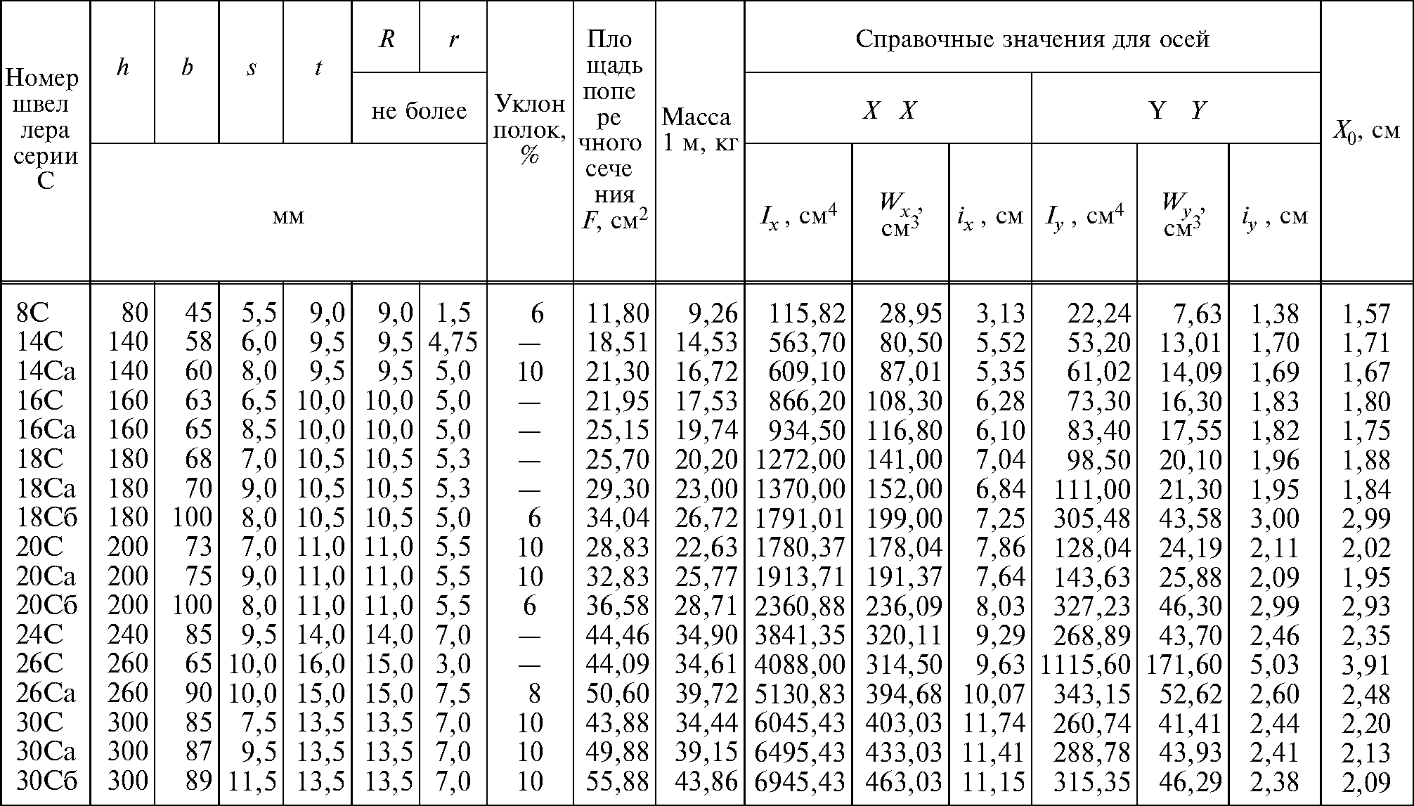
2.3 Dimensions of channels, cross-sectional area, weight 1 m and reference values for axles should correspond to those given in tables 1-5.
2.3.1 The cross-sectional area and the mass of 1 m of the channel are calculated according to the nominal dimensions, the steel density is assumed to be 7.85 g/cm 3 .
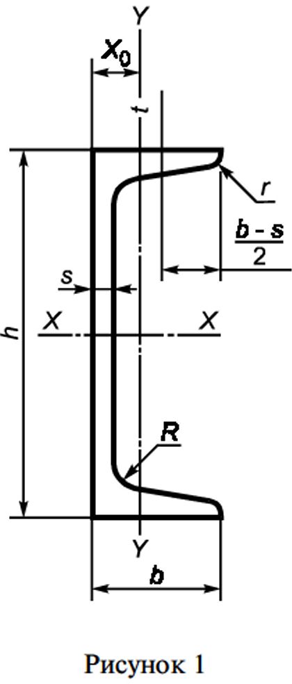
Table 1 - Channels with a slope of the inner edges of the shelves
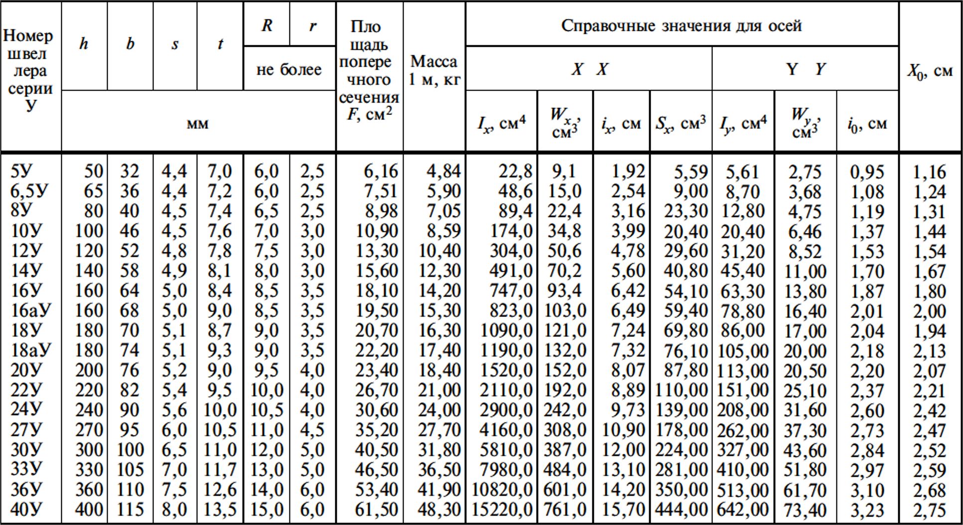
Table 2 - Channels with parallel flange edges
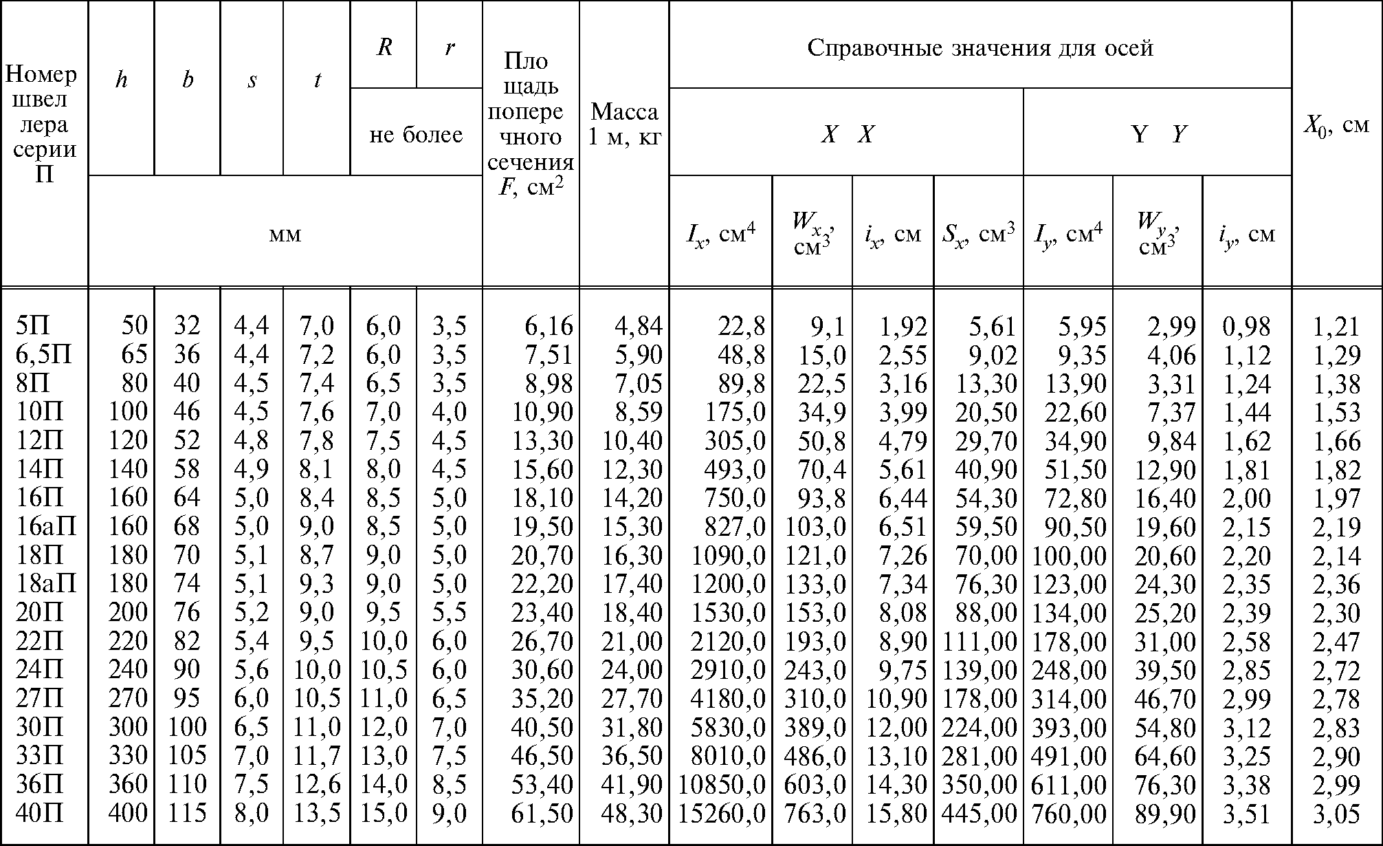
Table 3 - Economic channels with parallel flange edges
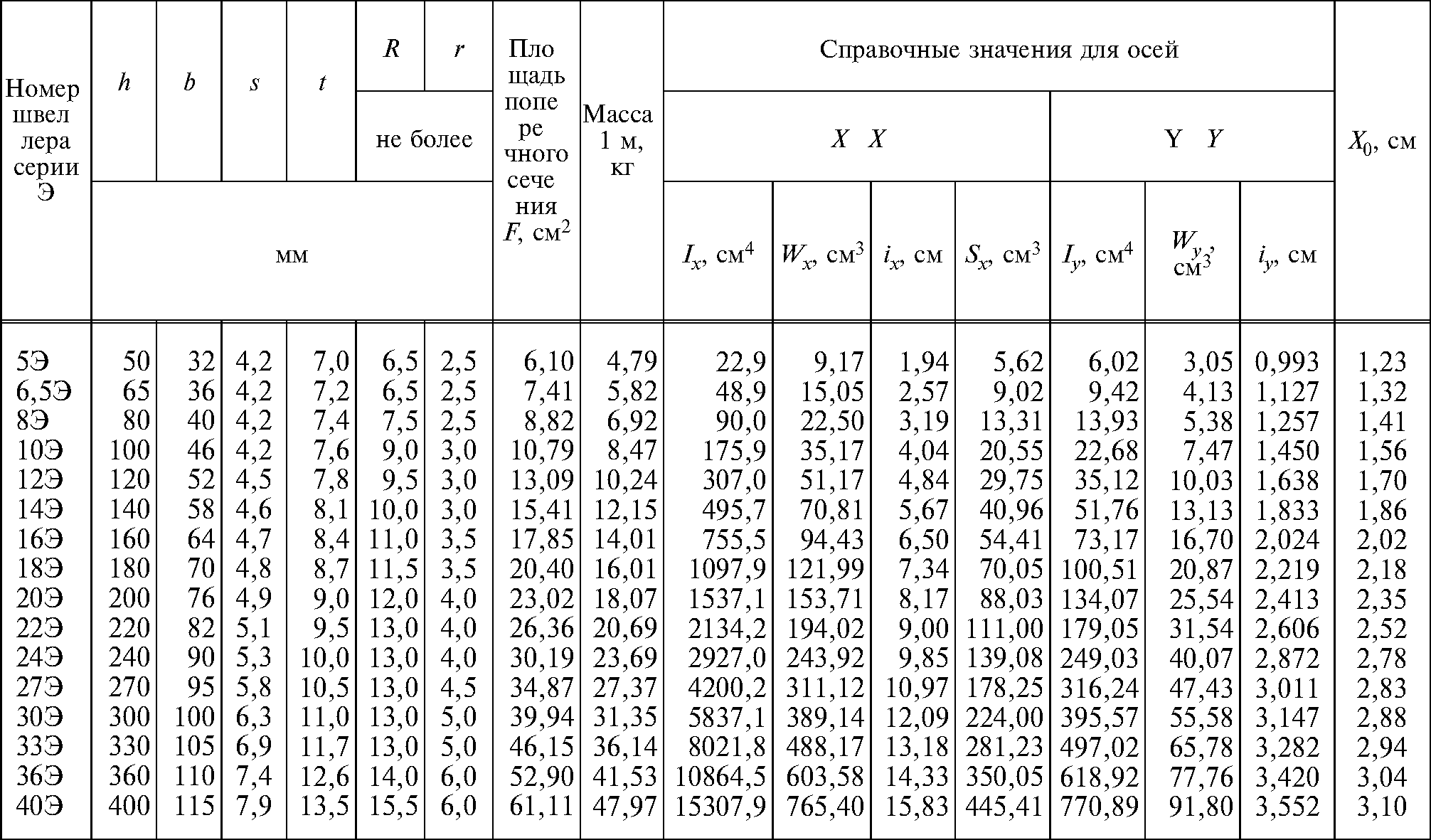
Table 4 - Light series channels with parallel flange edges
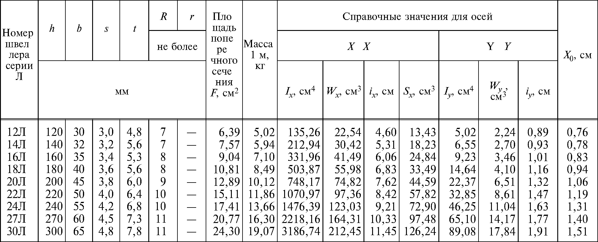
Table 5 - Special channels
2.3.2 The values of the radii of curvature, the slope of the inner edges of the shelves, indicated in Figures 1 and 2 and given in Tables 1-5, are used to build gauges and are not controlled on the profile.
2.4 The shape of the channel and the maximum deviations in size must correspond to those shown in Figure 3 and Table 6.
2.4.1 The slope of the inner edges of the flanges of U-series channels should be in the range from 4% to 10%.
By agreement between the consumer and the manufacturer, the slope of the inner edges of the shelves should not exceed 8% at h< 300 мм и 5 % при h >300 mm.
2.5 The blunting of right angles of channels up to No. 20 should not exceed 2.5 mm, over No. 20 - 3.5 mm. The blunting of external corners is not controlled.
2.6 Channels are made from 2 to 12 m long, by agreement between the consumer and the manufacturer - over 12 m long:
- measured length;
- measured length with unmeasured in an amount of not more than 5% of the mass of the batch;
- multiple measured length;
- multiple measured length with unmeasured in the amount of not more than 5% of the mass of the batch;
- unmeasured length;
- limited length within unmeasured.
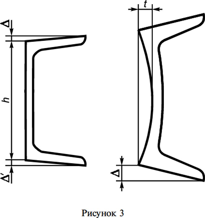
Table 6 - Limit deviations of parameters
In millimeters
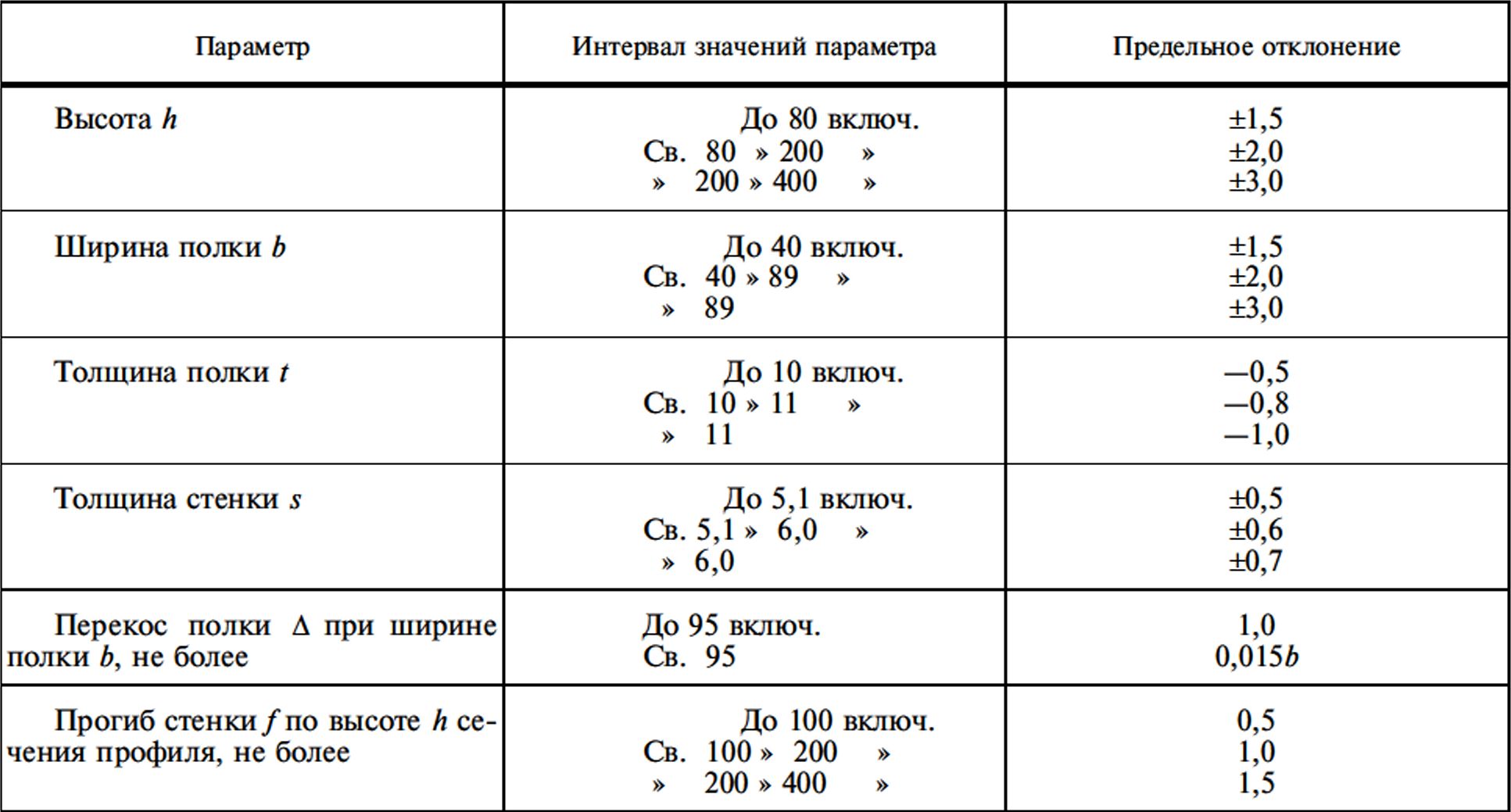
Notes
- For series L channels, the wall deflection should not exceed 0.15s.
- For U and P series channels, the maximum deviations in wall thickness are not controlled.
- Flange A misalignment and web/channel deflection are measured as shown in Figure 3.
2.7 Limit deviations along the length of channels of measured and multiple measured lengths should not exceed:
with a length of 2 to 8 m incl. — up to +40 mm; oh oh st. 8 m - up to + mm, but not more than 100 mm, where l is the length of the channel, m.
2.8 Channels must be cut. The oblique cut should not display the length of the channels beyond the limit deviations in length.
The length of an individual channel is the maximum length of a conditionally cut bar with ends perpendicular to the longitudinal axis.
2.9 The curvature of the channel in the horizontal and vertical planes should not exceed 0.2% of the length; by agreement between the manufacturer and the consumer - up to 0.15% of the length.
2.10 Limit deviations in mass should not exceed ±4% for a batch and ±6% for an individual channel.
Weight deviation is the difference between the actual weight as delivered and the weight calculated according to tables 1-5.
When calculating the mass of a batch, 0.5 of the sum of the maximum deviations along the length of the channels in the batch is added to the footage of channels of a measured or multiple measured length.
2.11 The dimensions and geometric shape of the channel are controlled at a distance of at least 500 mm from the end. The height of the channel is controlled in the plane of the wall, the wall thickness - at the end of the profile.
UDC 669-423.2:338.33:006.354 MKS 77:140.70 V22 OKP 29 2500


