Online calculation of beam profile. The program for the calculation of single-span wooden beams
To select the cross section of the beam, you must first determine the maximum bending moment in it ( M ) and on it for specific dimensions of the beam section (width and height) the maximum stress is determined ( ). The cross section is chosen so that this stress ( ) did not exceed the calculated resistance of the beam material (in this case, wood) R u . To ensure the economy of the choice of section, it is necessary that the difference between and R u was as small as possible. Such a calculation refers to “calculations for bearing capacity” (otherwise “calculations for group I of limit states”).
After selection of the section according to the bearing capacity, “calculation by deformations” is carried out (in other words, “calculation by group II of limit states”), i.e. the deflection of the beam is determined and its admissibility is evaluated. If, with a beam section selected according to the bearing capacity, the deflection is greater than the permissible one, the section is additionally increased, if less, it is left unchanged.
2.5. Bearing capacity calculation
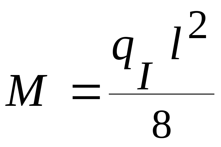
Maximum bending moment M in the beam is determined according to the rules of mechanics (strength of materials) by the formula
where q )
l - beam span ( m).
Stress in the beam is determined by the formula
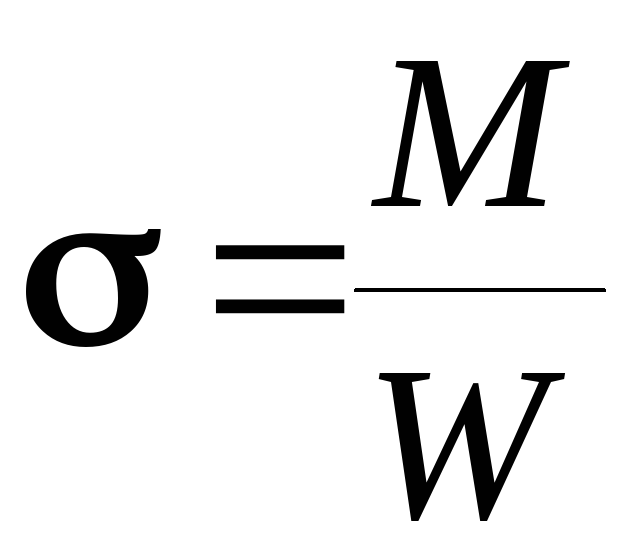 ,
(2)
,
(2)
where M - bending moment ( kNm) determined by formula (1),
W– section modulus ( m 3 ).
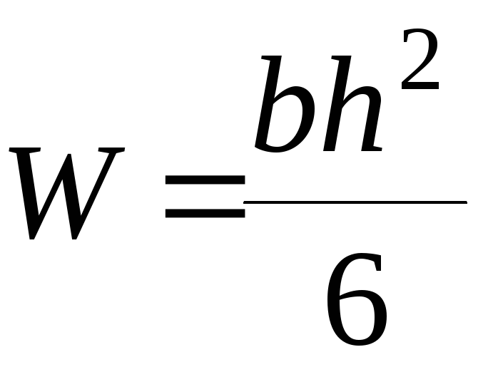 ,
(3)
,
(3)
where b, h- respectively, the width and height of the beam section.
Example. Beam span l = 3.6 I = 2.56 kN/m. Check beam section 0.10.2 m(large side - height).
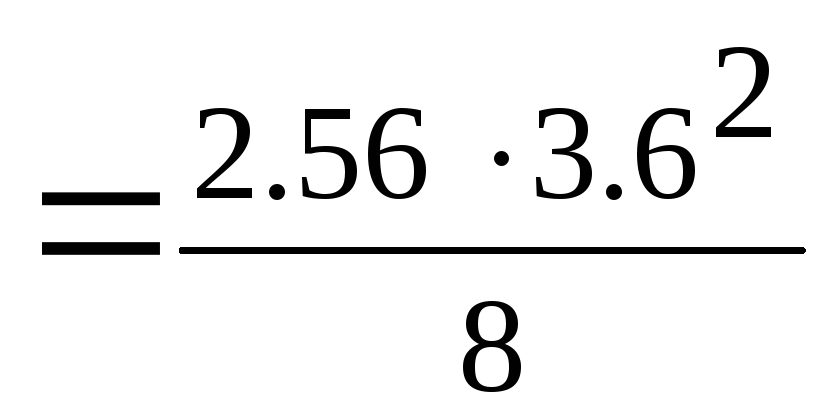 =
4.15 kNm
=
4.15 kNm
 =
0.00056 m 3
=
0.00056 m 3
 =
6 200 kN/m 2
(kPa) =6.2 MPa<
R u
=13 MPa
=
6 200 kN/m 2
(kPa) =6.2 MPa<
R u
=13 MPa
Thus, the cross section is 0.10.14 m satisfies the strength (load-bearing capacity) requirements, however, the maximum stress obtained about half the design resistance of wood R u, i.e. "margin of safety" is unreasonably large. Reduce the cross section to 0.10.14 m and check the possibility of its acceptance.
W  =
0.000327m 3
=
0.000327m 3
 =
12 691kPa
= 12.7 MPa<
13 MPa
=
12 691kPa
= 12.7 MPa<
13 MPa
"Margin" at a section of 0.1 0.14 m less than 5%, which fully satisfies the requirements of economy. Thus, we accept (at this stage) the cross section 0.1 0.14 m.
2.6. Deformation calculation
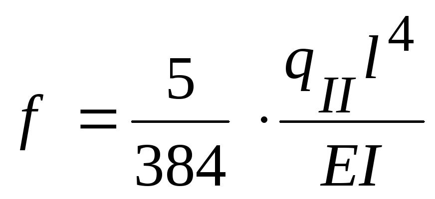
beam deflection f determined by the formula (resistance of materials)
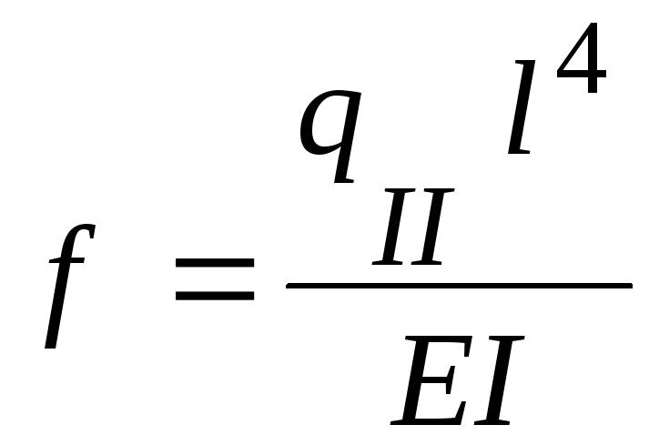 ,
(4)
,
(4)
where) in relation to deformation calculations (see Table 4);
l - beam span ( m);
E is the modulus of elasticity of the beam material, i.e. wood (kPa);
I – moment of inertia of the beam section ( m 4)
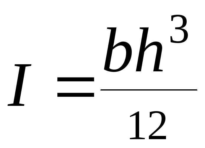 ,
(5)
,
(5)
where the designations are the same as in formula (2).
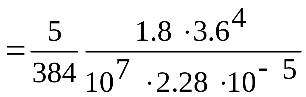
II =1.8 kN/m, E = 10 000 MPa = 10 7 kPa (see section 3.1), beam span l = 3.6m. Check beam section 0.10.14 m.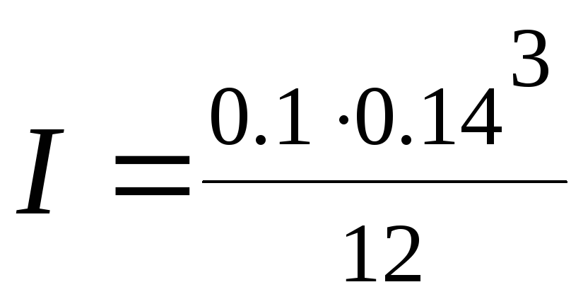 =
0.0000228 m 4
= 2.28
10 -5 m 4
=
0.0000228 m 4
= 2.28
10 -5 m 4
 =
0.0173m=
1.73 cm
=
0.0173m=
1.73 cm
Relative beam deflection, i.e. deflection ratio f to the span l, is in this case
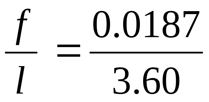 =
=

 <
<
The resulting relative deflection is less than the allowable one (1/200). In this regard, we accept the cross section of the beam 0.10.14 m as the final, satisfying the requirements of not only bearing capacity, but also deformability.
Obviously, any other building structure must also meet the requirements for both load-bearing capacity and deformability. Verification of the compliance of its parameters with both requirements is not carried out only in cases where it is clear without calculation that one of the requirements is certainly satisfied.
The program for the calculation of wooden floor beams- a small and handy tool that will simplify the basic calculations for determining the cross section of the beam and the step of its installation when constructing interfloor floors.
Instructions for working with the program
The considered program is small and does not require additional installation. 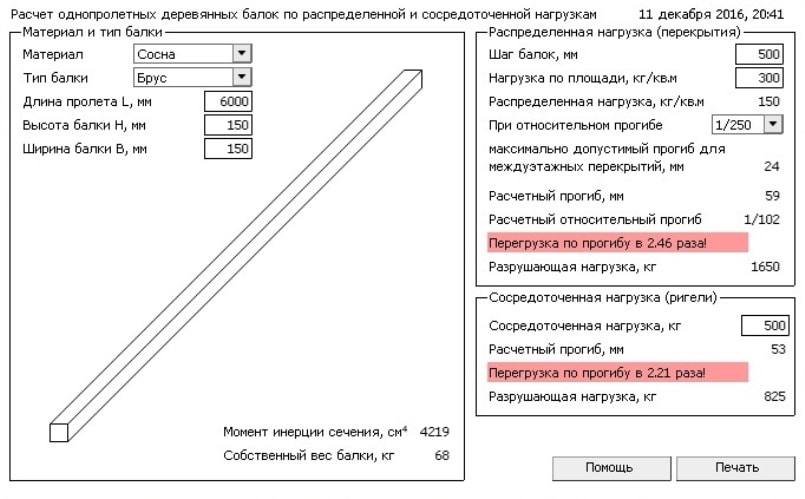
To make it clearer, consider each item of the program:
- Material- select the required material of timber or logs.
- beam type- beam or log.
- Dimensions- length height width.
- Beam spacing- the distance between the beams. By changing this parameter (as well as the dimensions), you can achieve the optimal ratio. . As a rule, the calculation of the load on the floors is carried out at the design stage by specialists, but you can do it yourself. First of all, the weight of the materials from which the floor is made is taken into account. For example, an attic floor, insulated with a light material (for example, mineral wool), with a light lining, can withstand a load from its own weight within 50 kg / m². The operational load is determined in accordance with regulatory documents. For attic floors made of wooden base materials and with light insulation and lining, operating load in accordance with SNiP 2.01.07-85 calculated in this way: 70 * 1.3 \u003d 90 kg / m². 70 kg/m². In this calculation, the load is taken in accordance with the standards, and 1.3 is the safety factor. : 50+90=140 kg/m². For reliability, the figure is recommended to be rounded slightly up. In this case, you can take the total load as 150 kg / m². If the attic is planned to be used intensively, then it is required to increase the standard load value to 150 in the calculation. In this case, the calculation will look like this: 50 + 150 * 1.3 = 245 kg / m². After rounding up - 250 kg/m². It is also necessary to carry out the calculation in this way if heavier materials are used: heaters, filing to fill the interbeam space. If an attic is to be built in the attic, then the weight of the floor and furniture must be taken into account. In this case, the total load can be up to 400 kg/m².
- With relative deflection. The destruction of a wooden beam usually occurs from transverse bending, in which compressive and tensile stresses occur in the cross section of the beam. At first, the wood works elastically, then plastic deformations occur, while in the compressed zone, the extreme fibers (folds) are crushed, the neutral axis falls below the center of gravity. With a further increase in the bending moment, plastic deformations increase and destruction occurs as a result of rupture of the extreme stretched fibers. The maximum relative deflection of beams and girders of roofing should not exceed 1/200. is the load taken from the slab (full) plus the own weight of the crossbar.
When designing the roofing system of a small building (private house, garage, barn, etc.), load-bearing elements such as single-span wooden beams are used. They are designed to cover the spans and act as the basis for laying the flooring on the roof. At the stage of planning and creating a project for a future building, it is mandatory to calculate the bearing capacity of wooden beams.
Wooden beams are designed to cover the spans and act as the basis for laying the flooring on the roof.
Basic rules for the selection and installation of single-span beams
The process of calculating, selecting and laying load-bearing elements should be approached with all responsibility, since the reliability and durability of the entire floor will depend on this. Over the many centuries of the existence of the construction industry, some rules for the design of a roofing system have been developed, among which the following are worth noting:
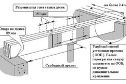
- The length of single-span beams, their dimensions and number are determined after measuring the span to be covered. It is important to consider how they are attached to the walls of the building.
- In walls built from blocks or bricks, load-bearing elements should be deepened by at least 15 cm if they are made of timber, and by at least 10 cm if boards are used. Beams should be deepened at least 7 cm into the walls from the log house.
- The optimal width of the span suitable for overlapping with wooden beams is in the range of 250-400 cm. In this case, the maximum length of the beams is 6 m. If longer bearing elements are required, then it is recommended to install intermediate supports.
Calculation of loads acting on the floor
The roof transfers the load to the load-bearing elements, which consists of its own weight, including the weight of the heat-insulating material used, the operating weight (objects, furniture, people who can walk on it in the course of performing certain works), as well as seasonal loads (for example, snow) . You are unlikely to be able to perform an exact calculation at home. To do this, you need to contact the design organization for help. Simpler calculations can be made independently according to the following scheme:
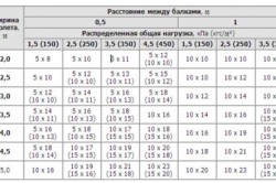
Figure 1. Table of the minimum allowable distance between beams.
- For attic floors, which were insulated with light materials (for example, mineral wool), which are not affected by large operational loads, we can say that on average 1 m 2 of the roof has a weight of 50 kg. According to GOST, for such a case, the load will be equal to: 70 * 1.3 \u003d 90 kg / m 2, where 1.3 is the margin of safety, and 70 (kg / m 2) is the normalized value for the above example. The total load will be equal to: 50 + 90 \u003d 140 kg / m 2.
- If a heavier material is used as a heater, then the normalized value according to GOST will be 150 kg / m 2. Then the total load: 150 * 1.3 + 50 \u003d 245 kg / m 2.
- For the attic, this value will be equal to 350 kg / m 2, and for the interfloor ceiling - 400 kg / m 2.
Having learned the load, you can begin to calculate the dimensions of single-span wooden beams.
Calculation of the section of wooden beams and laying step
The bearing capacity of the beams depends on their cross section and the laying step.. These quantities are interrelated, so they are calculated simultaneously. The optimal shape for floor beams is rectangular with an aspect ratio of 1.4: 1, that is, the height should be 1.4 times greater than the width.
The distance between adjacent elements should be at least 0.3 m and not more than 1.2 m. In the case of installing rolled insulation, they try to take a step that will be equal to its width.
If a frame house is being constructed, then the width is taken equal to the step between the racks of the frame.
To determine the minimum allowable dimensions of beams with a laying step of 0.5 and 1.0 m, you can use a special table (Fig. 1).
All calculations must be made in strict accordance with existing rules and regulations. If there is some doubt about the accuracy of the calculations, it is recommended that the obtained values be rounded up.


