Definition of reference. Definition of support reactions. Problem solving
Beams are designed to absorb transverse loads. According to the method of application, loads are divided into concentrated (acting on a point) and distributed (acting on a significant area or length).
q— load intensity, kN/m
G= q L– resultant distributed load
Beams have supporting devices to pair them with other elements and transfer forces to them. The following types of supports are used:
articulated movable
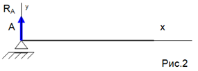
This support allows rotation around an axis and linear movement parallel to the reference plane. The reaction is directed perpendicular to the supporting surface.
Hinged-fixed
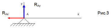
This support allows rotation around the axis, but does not allow any linear movement. The direction and value of the support reaction is unknown, therefore, it is replaced by two components R A y and R A x along the coordinate axes.
Rigid termination (pinching)
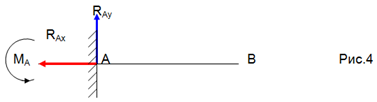
The support does not allow movement and rotation. Not only the direction and value of the support reaction are unknown, but also the point of its application. Therefore, the termination is replaced by two components R A y, R A x and moment M A. To determine these unknowns, it is convenient to use a system of equations.
∑ m A (F k) \u003d 0
To control the correctness of the solution, an additional equation of moments is used relative to any point on the cantilever beam, for example, point B ∑ m B (F k) \u003d 0
Example. Determine the support reactions of the rigid attachment of a cantilever beam 8 meters long, at the end of which a load P = 1 kN is suspended. Beam gravity G = 0.4 kN is applied in the middle of the beam.
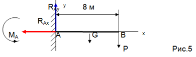
We release the beam from the bonds, i.e. we discard the termination and replace its action with reactions. We choose coordinate axes and compose equilibrium equations.
∑ F kx = 0 R A x = 0
∑ F k y = 0 R A y – G – P = 0
∑ m A (F k) \u003d 0 - M A + G L / 2 + P L \u003d 0
Solving the equations, we get R A y \u003d G + P \u003d 0.4 + 1 \u003d 1.4 kn
M A \u003d G L / 2 + P L \u003d 0.4. 4 + 1 . 8 = 9.6 books. m
We check the obtained reaction values:
∑ m in (F k) \u003d 0 - M A + R A y L - G L / 2 \u003d 0
— 9,6 + 1,4 . 8 – 0,4 . 4 = 0
- 11.2 + 11.2 = 0 reactions are found correctly.
For beams located on two articulated supports it is more convenient to determine the support reactions using the 2nd system of equations, since the moment of force on the support is zero and only one unknown force remains in the equation.
∑ m A (F k) \u003d 0
∑ m В (F k)= 0
To control the correctness of the solution, an additional equation is used ∑ F k у = 0
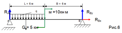
1) We release the beam from the supports, and replace their action with support reactions;
2) Replace distributed load to the resultant G = q. L;
3) Choose the coordinate axes;
4) Compose the equilibrium equations.
∑ F kx = 0 R In = 0
∑ m A (F k) \u003d 0 G. L/2 + m - R Wu (L + B) = 0
R Wu \u003d / (L + B) \u003d (6 + 6) \u003d 2.08 kn
∑ m В (F k)= 0 R A у. (L + B) - Q . (L/2 + B) + m = 0
R A y \u003d / (L + B) \u003d / (6 + 6) \u003d 2.92 kn
If you experience difficulties in writing, fill out an application and you will find out the terms and cost of the work.
5th semesterFundamentals of the functioning of machines and their elements in the industrial service system
Theoretical mechanics it is a science in which the general laws of mechanical motion and mechanical interaction of material bodies are studied.
Section 1. Statics is a section of mechanics that studies methods for converting systems of forces into equivalent systems and establishes the conditions for the equilibrium of forces applied to a solid body.
Force - this is a measure of the mechanical interaction of bodies, which determines the intensity and direction of this interaction. Strength is defined by three elements: numerical value (modulus), direction and application point. Force is represented by a vector.
Communication reaction is called a force or a system of forces that expresses the mechanical action of a connection on a body. One of the main provisions of mechanics is the principle of release of m bodies from bonds, according to which a non-free rigid body can be considered as a free one, on which, in addition to the given forces, the reactions of the bonds act.
Task 1. Determination of reactions of beam supports under the action of a plane arbitrary system of forces
Define reactions R A And R B beam supports, the dimensions and loads of which are shown in fig. 1a (change the values of F and M).
Solution. 1.Drawing up a calculation scheme.
Balance object - beam AC. Active forces: F
=
3ToH, pair of forces with M
=
4ToH∙m
=
1kN/m, which
replace with one concentrated force R q
=
q∙
1=
1∙
3
=
3ToH; attached to a point D at a distance of 1.5 m from the edge of the console. Applying the principle of release from bonds, we represent in points A And IN reactions. A plane arbitrary system of forces acts on the beam, in which three unknown reactions  And
And  .
.
Axis X direct along the horizontal axis of the beam to the right, and the axis y - vertically upwards (Fig. 1, a).
2. Equilibrium conditions:
 .
.
3. Compilation of equilibrium equations:
4. Determining the required values, checking the correctness of the solutionand analysis of the results.
Solving the system of equations (1 - 3), we determine the unknown reactions
from (2): kN.
Reaction magnitude R A X has a negative sign, it means that it is not directed as shown in the figure, but in the opposite direction.
To check the correctness of the solution, we compose the equation for the sum of the moments about the point E.
Substituting the values of the quantities included in this equation, we obtain:
0,58 ∙ 1 – 4 + 5,02 ∙ 3 – 3 ∙ 3,5 = 0.
The equation is satisfied identically, which confirms the correctness of the solution of the problem.
Task 2. Determination of reactions of supports of a composite structure
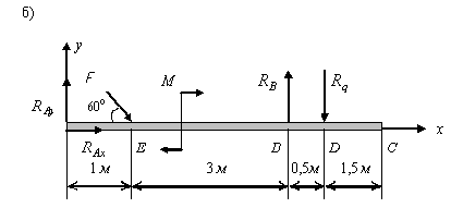
The structure consists of two bodies hinged at a point WITH. Body AC secured with embed, body Sun has a hinged-movable (sliding) support (Fig. 1). The bodies of the system are acted upon by a force distributed according to a linear law with a maximum intensity q max = 2 kN/m, force F = 4 kN at an angle α = 30 o and couple of forces with moment M = 3 kNm . The geometric dimensions are given in meters. Determine the reactions of the supports and the force transmitted through the hinge. The weight of the structural elements is not taken into account.
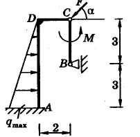
Rice. 1 Fig. 2
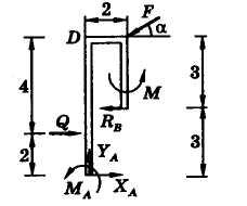
Solution.If we consider the balance of the entire structure as a whole, given that the embedment reaction consists of a force of unknown direction and a pair, and the reaction of the sliding support is perpendicular to the supporting surface, then design scheme will have the form shown in Fig. 2.
Here, the resultant of the distributed load
located at a distance of two meters (1/3 of the length AD) from the point A; M A- unknown closing moment.
In this system of forces, there are four unknown reactions ( X A , Y A , M A , R B), and they cannot be determined from the three equilibrium equations for a plane arbitrary system of forces.
Therefore, we divide the system into separate bodies along the hinge (Fig. 3).
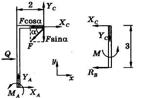
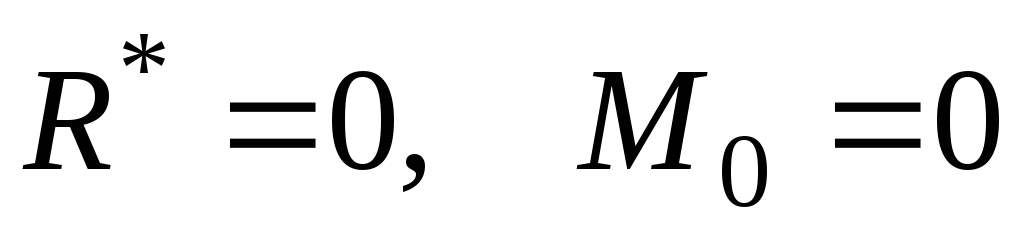
The force applied in the hinge should be taken into account only on one body (any of them). Body Equations Sun:
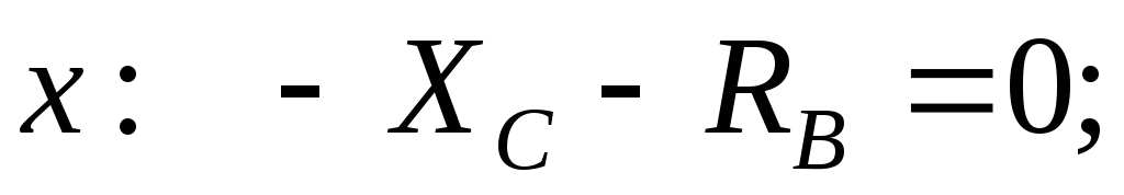
From here X WITH = – 1 kN; At WITH = 0; R B = 1 kN.
Body Equations AC:
Here, when calculating the moment of force F relative to the point A the Varignon theorem is used: force F broken down into components F cosα and F sin α and the sum of their moments is determined.
From the last system of equations we find:
X A = – 1,54 kN; At A = 2 kN; M A = – 10,8 kNm.
To check the obtained solution, we compose the equation of the moments of forces for the entire structure with respect to the point D(Fig. 2):
Conclusion: the test showed that the reaction modules were determined correctly. The minus sign of the reactions indicates that they are actually directed in opposite directions.
3. Bend. Determination of stresses.
3.3. Definition of support reactions.
Let's look at a few examples.
Example 3.1. Determine the support reactions of the cantilever beam (Fig. 3.3).
Solution. We represent the embedding reaction as two forces Az and Ay , directed as indicated in the drawing, and a reactive moment MA .
We compose the balance equation of the beam.
1. Equate to zero the sum of the projections on the z-axis of all forces acting on the beam. We get Az = 0. In the absence of a horizontal load, the horizontal component of the reaction is zero.
2. The same for the y-axis: the sum of the forces is zero. We replace the uniformly distributed load q with the resultant qaz applied in the middle of the section az:
Ay - F1 - qaz = 0,
Where
Ay = F1 + qaz .
The vertical component of the reaction in the cantilever beam is equal to the sum of the forces applied to the beam.
3. Compose the third equilibrium equation. We equate to zero the sum of the moments of all forces relative to some point, for example, relative to point A:
Where
The minus sign indicates that the direction of the reactive moment accepted at the beginning should be reversed. So, the reactive moment in the termination is equal to the sum of the moments of external forces relative to the termination.
Example 3.2. Determine the support reactions of the two-support beam (Fig. 3.4). Such beams are usually called simple.
Solution. Since there is no horizontal load, Az = 0 
Instead of the second equation, it was possible to use the condition that the sum of the forces along the Y axis is zero, which in this case should be applied to check the solution:
25 - 40 - 40 + 55 = 0, i.e. identity.
Example 3.3. Determine the reactions of the supports of a broken-shaped beam (Fig. 3.5).
Solution. 
those. reaction Ay is not directed upwards, but downwards. To check the correctness of the solution, you can use, for example, the condition that the sum of the moments about the point B is equal to zero.
Useful Resources on Determining Support Forces
1. , which will issue painted solution any beam. .
In addition to plotting diagrams, this program also selects the section profile according to the bending strength condition, calculates deflections and angles of rotation in the beam.
2. , which builds 4 types of diagrams and calculates reactions for any beams (even for statically indeterminate ones).