Hinged fixed support example. Schematization of supporting devices
A schematic representation of a movable hinged support is given in fig. 3.2b.
Movable supports allow the beam to freely change its length with temperature changes and thereby eliminate the possibility of thermal stresses.
2. Stationary pivot support(Fig. 3.2, c). Such a support allows rotation of the end of the beam, but eliminates its translational movement in any direction. The reaction arising in it can be decomposed into two components - horizontal and vertical.
3. Rigid sealing, or pinching (Fig. 3.2, d). Such fastening does not allow either linear or angular displacements of the reference section. In this support, a reaction can generally occur, which is usually decomposed into two components (vertical and horizontal) and a pinching moment (reactive moment).
67. How is the calculation for buckling in direct bending
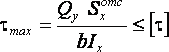
Strength condition for normal stresses
Where - the greatest modulus stress in the cross section; - bending moment; is the axial moment of resistance; – allowable normal stresses.
Strength condition for shear stresses
 ,
,
where is the greatest modulus stress in the cross section; - allowable shear stresses.
If different allowable normal stresses in tension and compression are specified for the beam material, then the strength conditions are applied separately to the most stretched and to the most compressed fibers of the beam.
71. What is the shaft system and hole system
The tolerance and fit standards in our industry establish two sets of fits that can be used - the hole system and the shaft system.
A hole system is a set of landings in which the maximum deviations of the holes are the same (with the same accuracy class and the same nominal size), and different landings are achieved by changing the maximum deviations of the shafts (Fig. 73, a). In all fits of the hole system, the lower limit deviation of the hole is always zero.
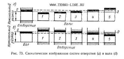
This hole is called the main hole. It can be seen from the figure that with the same nominal size (diameter) and a constant tolerance of the main hole, different fits can be obtained by changing the limiting dimensions of the shaft. Indeed, a shaft 1 of even the largest limiting diameter will freely enter the smallest hole. By connecting shaft 2 at its largest limit size with the smallest hole, we get a gap equal to zero, but with other ratios of the diameters of the hole and the shaft in this pairing, a movable fit is obtained. The landings of Balls 3 and 4 belong to the group of transitional ones, since with some values of the actual dimensions of the holes and shafts 3 and 4 there will be a gap, and with others an interference. Shaft 5 under all conditions will enter the hole with an interference fit, which will always ensure a fixed fit.
The main hole in the hole system is abbreviated with the letter A, in contrast to the designation of the second (non-main) part included in the mate, which is indicated by the letters of the corresponding fit.
The shaft system is a set of landings in which the maximum deviations of the shafts are the same (with the same accuracy class and the same nominal size), a various landings are achieved by changing the limit deviations of the holes. In all landings of the shaft system, the upper limit deviation of the shaft is always zero. Such a shaft is called the main shaft.
A schematic representation of the shaft system is given in fig. 73, b, from which it can be seen that with the same nominal size (diameter) and a constant tolerance of the main shaft, different fits can be obtained by changing the limiting dimensions of the hole. Indeed, by connecting hole 1 with this shaft, we will obtain a movable fit under all conditions. A similar fit, but with the possibility of obtaining a gap equal to zero, we will get when pairing holes 2 with this shaft. Shaft connections with holes 3 and 4 belong to the group of transitional landings, and with hole 5 - to a fixed fit.
The main shaft in the shaft system is abbreviated as B.
Figure 219.1. Dependence of the values of bending moments and deflections on the beam support option.
Figure 219.1.a shows a beam with hinged supports. For such a beam, the maximum bending moment M and, accordingly, the maximum normal stresses will act in the cross section located in the middle of the span, while the moment on the supports will be equal to 0. Figure 1.b shows a beam having the same span and the same load is applied to the beam as to the beam in the figure 219.1.a. In this case, for the beam shown in Figure 219.1.b, the maximum bending moments will act on the sections located on the supports, their value will be 1.5 times less than for the beam on hinged supports, and the maximum deflection f will be 5 times smaller.
As you can see the difference is noticeable. And for reinforced concrete structures determination of tensile and compressed areas is especially important, since reinforced concrete is a complex material in which concrete, like an artificial stone, works on compressive stresses, and metal reinforcement is usually installed in a tensile area, which makes it possible not to take into account the flexibility of the rods and thereby use the strength properties metal maximum. Thus, the correct determination of the type of supports will save a decent amount of material. In addition, since any beam, for example, a lintel or floor slab, has certain sections intended for support, such a beam can be considered as a two-cantilever beam with two hinged supports, in which the supporting sections are beam consoles, although with relatively small sizes of such sections it doesn't make much sense.
If you do not know what kind of support your structure will have, then take the articulated cantilever. The worst thing that can happen in this case is a safety margin of 1.5-2 times
Those who hope to save a little on the manufacture of the structure will have to read the article to the end. Well, now about the main thing: why are such concepts as hinged supports and rigid pinching on supports used in structural mechanics and strength of materials and how to live with it?
In most cases, the calculation of a building structure is simplified and approximate, which allows you to perform the calculation as quickly and simply as possible. For example, you need to calculate a jumper from a rolled profile, which will be laid on the mortar used in the construction brick wall. In order to perform the calculation as accurately as possible, in addition to the load acting on the lintel, you also need to know not only the span length, but also the total length of the lintel, taking into account the supporting parts, the strength of the masonry mortar and the compressive strength of the brick, the geometric shape of the bricks, the adhesive force of the metal with the mortar and the force of friction between the metal and the mortar, possible defects in the masonry mortar, rolled profile, straightness of the profile, the difference in the elevations of the supporting platforms, and much more. However, structural mechanics, if taken for a lintel articulated support without consoles, allows you to simplify the calculation to a minimum when using the following tolerances and design assumptions:
1. The bulkhead is considered as a homogeneous body with isotropic properties, i.e. identical physical and mechanical properties in all directions. This allows us to consider the jumper as an absolutely flat rectilinear rod lying on the axis X . Axis X passes through the center of gravity of the bar cross sections. Load applied along the axis at , i.e. hits the axle X passing through the centers of gravity of the cross sections.
2. Since the rod is absolutely flat, the supporting sections of the jumper are reduced to two reference points BUT and AT, while the internal stresses acting on the support sections along the axis at are reduced to concentrated loads, which in this case are support reactions. Since the support platforms and support sections of the beam are reduced to points, the concentrated support reactions are applied at the support points. Thus, in the calculations, not the full length of the jumper is used, but the span of the beam l - distance between reference points.
3. The action force is equal to the reaction force, for example, the total load acting on the jumper is equal to the sum of the support reactions.
4. The force of adhesion of the metal to the solution and the friction force that occurs when the beam moves along the axis X , are taken sufficient to ensure the immobility of the beam along this axis at the reference point BUT and are not taken into account for the reference point AT. In other words, at the point BUT beam to move along the axis X can't, but at the point AT can freely.
5. Since the jumper will bend under the action of the load, then on the design diagram it is necessary to somehow indicate the distance between the ground and the jumper.
The following design scheme most fully meets these design assumptions:
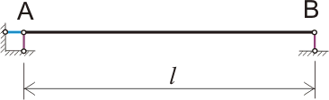
Figure 219.2. Articulated non-cantilever beam.
The essence of this design scheme is as follows: our jumper is a rod that is pivotally connected to three conditional support rods that have infinitely high strength, rigidity and length, sufficient to ensure free deflection of the beam and, at the same time, displacement of the beam at the point AT due to a change in linear dimensions during deflection, it will occur only along the axis X . The friction force in the hinges is 0, the support rods are also hinged to the ground. In this case, the vertical rods, indicated in Figure 2 in purple, are parallel to the axis at , and the horizontal rod, marked in blue in Figure 2, is located on the axis X like the main beam. This position of the support rods provides a geometrically unchanging design. This allows us to replace the support rods with three support reactions and in the calculations to manage with three basic equilibrium equations, here we do not perform any calculations, and therefore the equilibrium equations are not given (the values of the moments determined based on the equilibrium equations are given in Figure 219.1.a). In principle, with such a design scheme, the calculation of a jumper takes no more than half an hour, and most of the time is spent on collecting loads. Hinged supports can be depicted in a different way, especially for cantilever beams, for example, as shown in Figure 219.1.a), one of the supports can be designated conditionally sliding, but no matter how the hinged supports are depicted, the physical meaning of the design scheme for hinged on two supports remains unchanged.
This calculation scheme can be taken for most building structures that have two supports and at the same time a relatively small support area, for example, when calculating wooden, metal and reinforced concrete floor beams (if reinforced concrete beams will be manufactured separately from the floor slab), for floorboards and reinforced concrete floor slabs supported by two walls, for lintels. In this case, the influence of nails, screws or mortar on the operation of the structure can be ignored. But
if the length of the bearings is greater than 1/3 of the span length for lintels or greater than 1/8 of the span length for floor slabs in buildings with heavy material walls, then it makes sense to check whether the structure can be considered as pinched on supports.
From the point of view of structural mechanics, the rigid pinching on the supports, shown in Figure 219.1.b), can be replaced by support rods as follows:
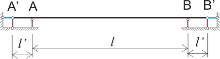
Figure 219.3. Replacing Pinched Supports with Swivel Supports
For a pinch to be considered rigid, the value l" should be significantly less l or rod on plots AA" and BB" must be absolutely rigid, subject to one of these conditions, the angle of rotation of the beam cross section at points BUT and AT will be equal to 0 or tend to 0. In reality, the first condition is feasible only if our beam is welded on the support (for metal frames) or welded and concreted (for reinforced concrete frames), and not by eye, but according to the calculation. Or load from above and below on the supporting sections of the beam l" will be significantly greater than the load on the beam, for example, with sufficient pinching reinforced concrete slab ceilings between bricks of the wall. But even this is not enough. Such a beam, pinched on two supports (Figure 1.b) or having 6 support rods (Figure 3), is three times statically indefinable beam, with all the ensuing consequences. In this case, as already mentioned, we do not do calculations, and there is no need for this, the main calculation formulas are shown in Figure 1.b, but we can already use the knowledge gained.
Well, the main difference between a rigidly clamped support and a hinged support is that the angle of rotation of the cross section of a beam (rod) on a rigidly clamped support is always equal to 0, regardless of where and how the load is applied, and on hinged supports, the angle of inclination of the cross section is usually maximum. This ultimately results in such a tangible difference in the deflection values.
Examples of the influence of the length of the support sections
1. And now consider the case closest to reality
The lintel above the opening in the brick wall has supporting sections of a certain length, it is applied evenly to the lintel distributed load, in other words, a brick rests on the lintel. Such a jumper can be conditionally considered as a two-cantilever beam on two hinged supports with a uniformly distributed load. It is required to choose the length of the consoles so that the bending moment on the supports is equal to the maximum moment in the span. The task, despite the complexity of the formulation, is very simple. Since for a non-cantilever beam on two hinged supports, the maximum bending moment will be equal to q l 2 /8 , then for a cantilever beam with the same span l we need to choose such a length l" so that the condition M max for span = M on supports = ql 2 /16. Why so, I will not explain here, take my word for it (however, at the request of the students, I wrote a separate article about the features of the calculation of slant beams with symmetrically loaded consoles). Thus, the moment on the support from the distributed load will be q l 2/16 = q l" 2 /2 . Therefore, the length of the supporting sections of the jumper should be
l" = l /(√8 ) ≈ 0.3535l
For example, for a lintel laid over a span of 2 meters long, the length of one supporting section must be at least 0.7 m, and the total length of the supporting sections must be at least 1.4 m, so that the lintel can be calculated as a two-cantilever beam on two hinged supports. And if for a jumper over a two-meter span such a length of the support section is a lot, then for a jumper over an opening of 1 meter, the length of the support sections of 36 cm no longer seems so large compared to the minimum required of 25 cm, and thus sometimes you can choose such sizes jumpers, which will allow almost 2 times to save on materials. There are some features that must be taken into account when calculating:
- An increase in the length of the support sections will lead to an increase in the moment on the supports and the beam will approach with a rigidly clamped on the supports;
- Reducing the length of the support sections will lead to an increase in the moment in the span and the beam will approach the non-cantilever hinged beam;
- The load, which we accept as uniformly distributed, is in fact not such, besides, when the volume load is reduced to a flat plane, the plane of application of such a load will not always coincide with the plane passing through the centers of gravity of the sections.
These features can be taken into account by a correction factor, for example, 1.2 or 1.3. If we multiply the moment value by a correction factor of 1.5, then this will already be a rigidly clamped beam.
2. Another example
The floor slab rests on a 77 cm wide brick wall (this is the wall thickness that is often required to provide the necessary thermal insulation by modern building codes if the wall is not additionally insulated), the span of the slab l l" = 0.6 m. Distributed load on the floor slab q 1 q2= 4000 kg/m.
It is required to check whether such a slab can be considered as a beam rigidly fixed on supports, or as a cantilever beam on hinged supports.
Note: if the length of the supporting section of the beam is less than the height of the cross section of the beam, then the load from the weight of the wall due to the redistribution of stresses is not taken into account and the beam is considered as a non-cantilever on hinged supports. In this case, if the height of the beam h is in the range of 10-20 cm, then the length of the supporting section of the beam is much greater than the height of the section, and therefore the load from the weight of the wall must be taken into account, while the load from the entire width of the wall must be taken into account, since the length of the supporting sections is comparable to the thickness of the wall. The moment on the supports will be
M supports \u003d 4000 0.6 2 / 2 \u003d 720 kg m,
M span \u003d 500 4 2 / 8 \u003d 1000 kg m,
thus, the maximum moment in the span of the floor slab will be 280 kg m, which is less than 1000/3 = 333 kg m, and therefore such a floor slab should be considered as rigidly clamped on supports.
Note: Even in this case, the angle of rotation of the cross sections at the beginning of the support sections will not be equal to zero, since both the beam and the wall material do not have infinitely greater rigidity. This means that for a more accurate calculation, the span of a rigidly clamped beam should be taken larger than the actual distance between the walls on which the beam rests. Furthermore, calculated value the span can be even greater than the length of the beam itself, especially if the modulus of elasticity of the beam is significantly greater than the modulus of elasticity of the wall material.
3. Another example
The floor slab rests on a brick wall 51 cm wide (this is the thickness of the walls that is still often done), the span of the slab is the same l = 4 meters, the length of the supporting sections per floor slab l" = 0.38 m. Distributed load on the floor slab q 1\u003d 500 kg / m, distributed load from the weight of a brick wall (depending on the brand and composition of the brick, the height of the masonry and other reasons) q2= 4000 kg/m. It is required to check whether such a slab can be considered as a beam rigidly fixed on supports, or as a cantilever beam on hinged supports. The moment on the supports will be
M supports = 4000 0.38 2 /2 = 288.8 kg m,
moment in the span for a cantilever beam on hinged supports
M span \u003d 500 4 2 / 8 \u003d 1000 kg m,
Thus, the maximum moment in the span of the floor slab will be 711.2 kg m, which is more than 333 kg m, and therefore such a floor slab should be considered as a cantilever beam with hinged supports.
Note: if we consider such a floor slab as a cantilevered beam on hinged supports, then the maximum bending moment for which the cross section must be calculated will be 40% more. However, as in the first example, everything is not so simple, and it is advisable to use a correction factor to take into account unaccounted for circumstances.
Of course, the support platforms on which the beam will rest must be separately
Lecture #3
Topic: " Internal forces in the cross sections of the rod "
Questions:
1. Supports and support reactions, and their definition
3. Relationship between Bending Moment, Shear Force and Distributed Load Intensity
1. Supports and support reactions, and their definition
When calculating structures, there are mainly elements that experience bending. Rods that work mainly in bending are called beams. In order for the beam to be able to experience the load and transfer it to the base, it must be connected to it by support links. In practice, several types of support connections are used, or, as they say, several types of supports.
There are three main types of supports:
a) hinged movable support:
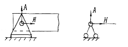
b) hinged-fixed support:
c) hard closure.
Rice. one
On fig. 1 shows a hinged movable support, such a support allows the beam to freely rotate and move in a horizontal direction. Therefore, the reaction in the support will be one - the vertical force. The symbol for such a support is shown on the right.
Rice. 2
On fig. 2 shows a hinged-fixed support. Such a support allows the beam to rotate freely, but it cannot move. Therefore, two reactions can occur - vertical and horizontal forces. You can add them up and get one resultant force, but you need to know the angle at which it will be directed. It will be more convenient to use the vertical and horizontal components of the reaction.
On fig. 3 shows a rigid termination. It does not allow the beam to turn or move. Therefore, three support reactions can occur: moment, vertical and horizontal forces. If the beam does not have a support at the end, then this part of it is called a console.
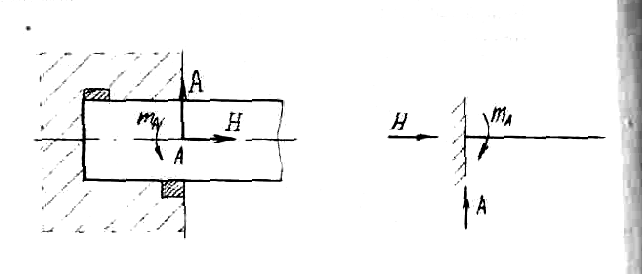
Rice. 3
Let's determine the reactions of the supports for the beam (see Fig. 4).
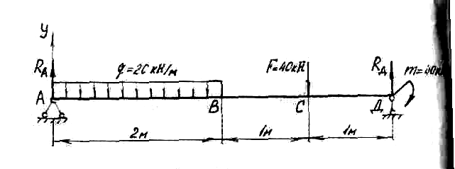
Fig.4
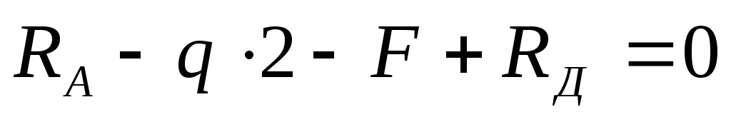
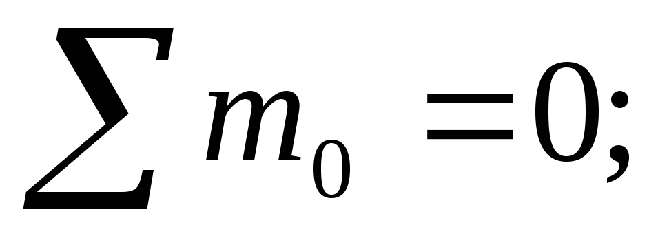
In support A, the horizontal reaction is zero, since the distributed load q and the concentrated force F have a vertical direction. Support reactions  let's go up. Let us compose two equations of the static balance of forces. The sum of the moments about each of the supports is zero. Moment equations must be drawn up relative to the supports, since in this case equations with one unknown are obtained. If we make equations for points B and C, we get equations with two unknowns, and it is more difficult to solve them. Counterclockwise moments will be considered positive, clockwise moments negative.
where  moment from a uniformly distributed load.
Work q to the distance at which it is applied, from the equilibrium condition of the system is equal to the concentrated force applied in the middle of the segment. Therefore the moment equals:
 -moment of power F
External moment m is not multiplied by the shoulder, since it is a pair of forces, i.e. two equal in magnitude, oppositely directed forces that have a constant shoulder.
 .
.
Check: The sum of all forces on the vertical Y-axis must be equal to zero:
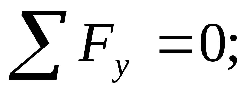
 .
.
Moment m into the condition of static equilibrium do not write down, since the moment is two equal in magnitude, oppositely directed forces and in the projection on any axis they will give zero.
30-20-2-40+50=0:
80-80=0.
Reactions are defined correctly.
2. Shear force and bending moment
Let the forces act on the beam  , support reactions
  . Let us determine the internal forces in the section located at a distance from the zero end (see Fig. 5).
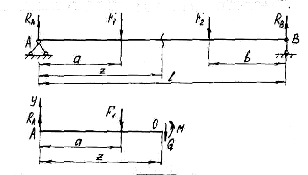
Rice. 5
Since all external forces act vertically, the horizontal component of the support reaction BUT will not. The beam will not compress or stretch, i.e. the longitudinal force in the cross sections is zero. One could take an example when the forces would not be vertical in direction. Then would be in support BUT there would be a second reaction - a horizontal force, and in beam sections - a longitudinal force N. In this case, the beam would experience bending with tension (compression), i.e. would be a case of complex resistance. We will study it later. Consider the simpler problems first and move on to the more complex ones, and not vice versa.
Since external forces  lie in the same plane passing through the axis of the beam, then the occurrence of trex internal forces is possible: bending moment M, transverse force Q
and longitudinal force N, which, as we noted, is equal to zero. Values M and Q
we determine from the equation of static equilibrium of the left side of the beam:
lie in the same plane passing through the axis of the beam, then the occurrence of trex internal forces is possible: bending moment M, transverse force Q
and longitudinal force N, which, as we noted, is equal to zero. Values M and Q
we determine from the equation of static equilibrium of the left side of the beam:
Conclusion: the transverse force in the section is numerically equal tothe algebraic sum of all external forces, and the bending moment the sum of all the moments calculated with respect to the section andapplied to the considered part of the beam.
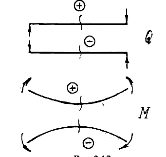
For shear forces and bending moments, mandatory sign rules are adopted (see Fig. 6).
If the force tries to rotate the considered part of the beam clockwise, then it causes a positive transverse force, and, conversely, if it acts counterclockwise, then the transverse force is negative. On fig. 5 strength  causes positive Q,
a
causes positive Q,
a  - negative. It should be noted that the force direction positive for the left side will be negative for the right side. This is due to the fact that the internal forces acting on the right and left sides of the beam must necessarily be equal and oppositely directed.
If an external force or an external moment bends the beam with a convexity downwards, then the resulting bending moment is positive and, conversely, with a convexity upwards, it is negative.
Rice. 6
3. Relationship between bending moment,
transverse force and distributed load intensity
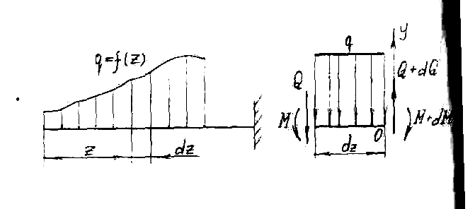
Let a cantilever beam (see Fig. 7) be subjected to a distributed load that varies along the length of the beam. On distance z from the left end we take an infinitesimal segment dz.
Rice. 7
Then the distributed load on it can be considered as a constant. On the left side of the segment under consideration there will be internal forces Q and M, on the right - taking into account the increment of internal forces Q+ dQ and M+ dM.
Let us compose the equations of static equilibrium for the beam segment:
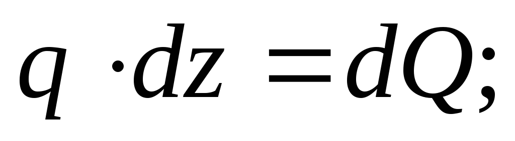
 (1)
(1)
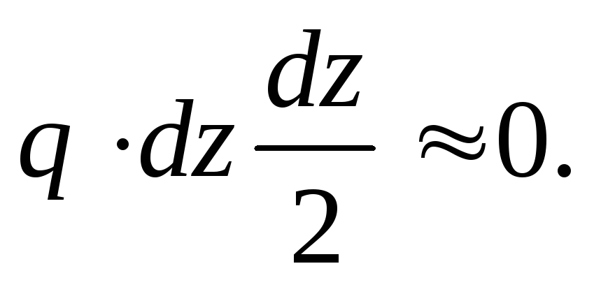
The third term can be neglected as an infinitesimal value of a higher order, i.e.:
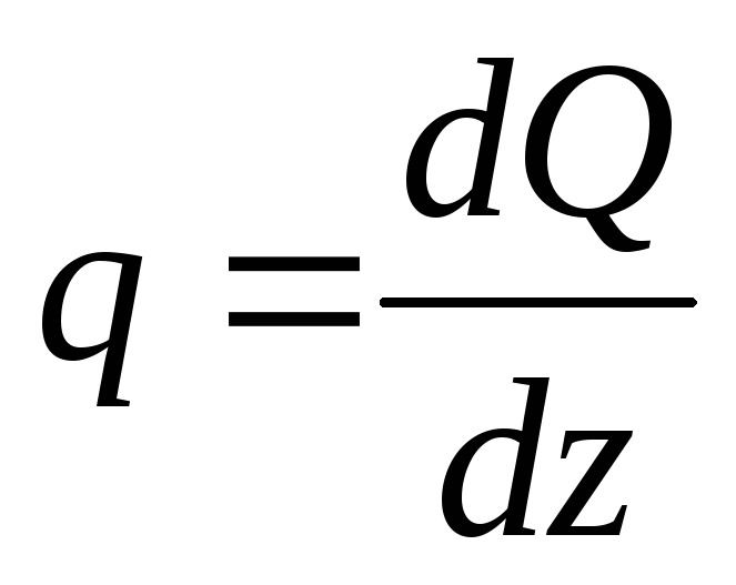
After transformations, we get:
 (2)
(2)
those. the first derivative of the bending moment along the abscissa (length of the beam) is the transverse force.
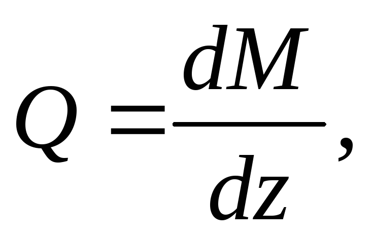
If in formula (1) we substitute the value Q from formula (2), we get:
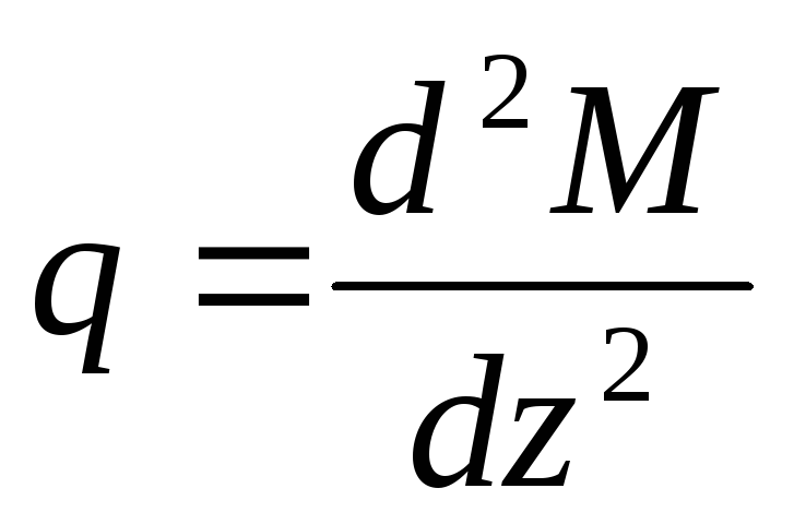 , (3)
, (3)
those. the second derivative of the bending moment is the intensity of the distributed load.
Spatial solid has six degrees of freedom of movement - three translational movements and three rotational around three mutually perpendicular axes. A flat body has only three degrees of freedom - two translational movements in the direction of two axes and rotation around the third axis. The support devices prevent one or another of the indicated movements of the body or generally exclude any of its movement. Reference devices are classified according to the number of connections imposed on the displacement of reference points (nodes) of the body. The connection is usually represented in the form of a rod connecting the body to the supporting surface. Unless otherwise specified, support links and surfaces are assumed to be absolutely rigid.
When a body is loaded on it from the side of the support connections, forces called support reactions begin to act. The support reactions are found from the equilibrium equations of the body, in which the support links are mentally removed and replaced by forces directed along the removed links.
For flat body, and in particular for a flat bar, the main types of supports are articulated, hinged-fixed and pinching fixed.
Hinged-movable, or, in other words, the roller support excludes the movement of the support unit BUT in the direction perpendicular to the reference surface, but does not prevent the rotation of the body around the reference point and translational movement parallel to the reference surface. Such a support corresponds to one support reaction directed perpendicular to the supporting surface. Schematic images of the roller bearing are shown in fig. 1.3. The direction of the support reaction is also shown.
Rice. 1.3. Articulated support
Hinged-fixed, or, in short, the hinged support eliminates any translational movement of the support assembly A, but does not prevent the rotation of the body around the reference point. The reaction of such a support, the direction of which is not known in advance, is usually decomposed into two components Rx and Ry, directed tangentially and normal to the reference surface, as shown in fig. 1.4. The same figure shows schematic representations of hinged supports.
Rice. 1.4. Hinged-fixed support
Pinching fixed support, or, in other words, termination (Fig. 1.5) excludes translational and rotational movements of the body. In accordance with the three bonds imposed on the body, the embedding reactions are the forces R x and Ry and anchor point M. The design of the support devices of each of these types is very diverse. In the fig. 1.3, 1.4 and 1.5 generally accepted schematic representations of supports emphasize their most characteristic features.
Rice. 1.5. fixed support


