How to connect an electronic ammeter to the charger. Built-in digital voltmeter-ammeter
I received a couple of electronic built-in voltmeters from AliExpress model V20D-2P-1.1 (measurement of direct voltage), the issue price is 91 cents a piece. Here are its characteristics:
- operating range 2.5 V - 30 V
- glow color red
- overall size 23 * 15 * 10 mm
- does not require additional power (two-wire version)
- it is possible to adjust
- update rate: about 500ms/time
- promised measurement accuracy: 1% (+/-1 digit)
And everything would be fine, I put it in place and used it, but I came across information about the possibility of their refinement - adding a current measurement function.
 Digital Chinese Voltmeter
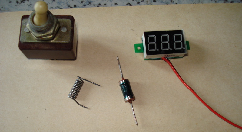
 I prepared everything you need: a bipolar toggle switch, output resistors - one MLT-1 for 130 kOhm and the second wire for 0.08 Ohm (made from a nichrome spiral with a diameter of 0.7 mm). And for the whole evening, according to the scheme found and the manual for its implementation, he connected this economy with wires to a voltmeter. To no avail. Either there was not enough ingenuity in understanding the unsaid and underdrawn in the found material, or there were differences in the schemes. The voltmeter didn't work at all.
 We connect the digital voltmeter module
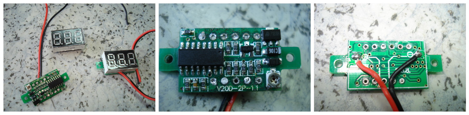
 I had to solder the indicator and study the circuit. Here it was already required not a small soldering iron, but a tiddly one, so that it tinkered fairly. But over the next five minutes, when the whole scheme became available for review, I understood everything. In principle, I knew that I should start with this, but I really wanted to solve the issue “easily”.
V-meter refinement scheme
 Refinement scheme: ammeter to voltmeter
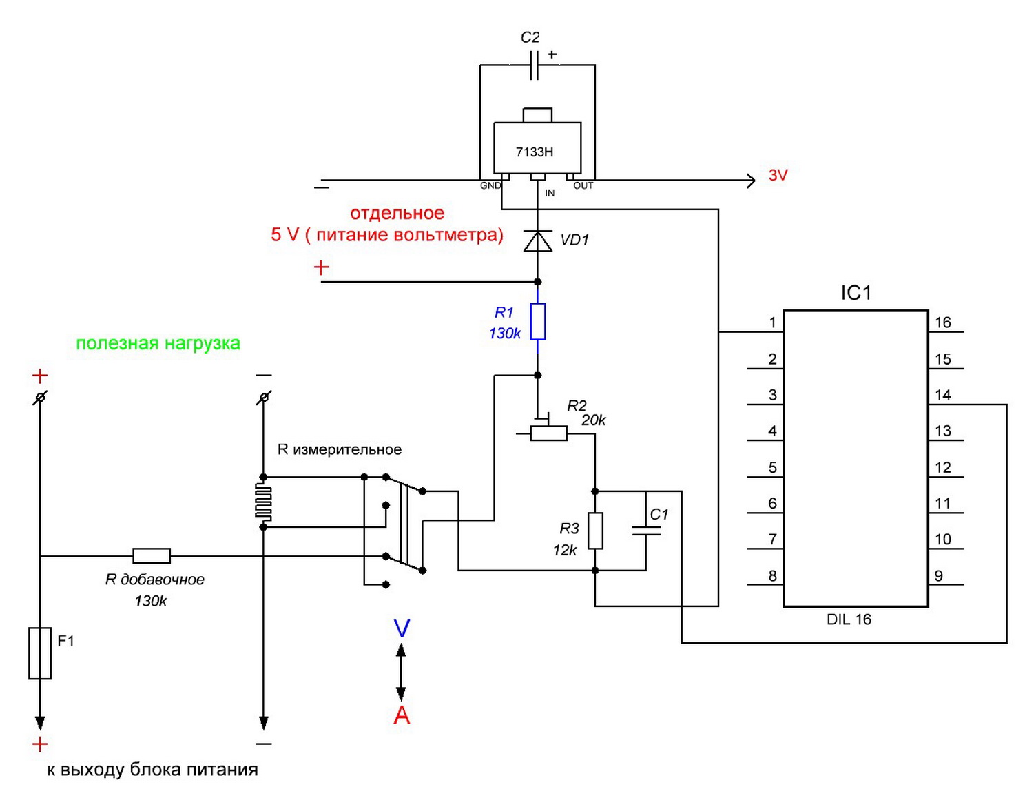
 So this scheme was born for connecting additional electronic components with those already existing in the voltmeter circuit. The standard circuit resistor marked in blue must be removed. I will say right away that I found differences from other circuits given on the Internet, for example, the connection of a tuning resistor. I didn’t redraw the entire voltmeter circuit (I’m not going to repeat it), I drew only the part that is necessary for refinement. I consider it obvious that the power supply of the voltmeter should be done separately, after all, the starting point in the readings should start from zero. Later it turned out that power from a battery or accumulator would not work, because the current consumption of a voltmeter at a voltage of 5 volts is 30 mA.
 Board - Chinese voltmeter module
 After assembling the voltmeter, he took up the essence of the action. I won’t be wise, I’ll just show and tell you what to combine with what to make it work.
Step-by-step instruction
So, act one- an SMD resistor with a resistance of 130 kOhm is soldered from the circuit, standing at the input of the positive power wire, between the diode and the trimming resistor of 20 kOhm.
 We connect the resistor to the voltmeter-ammeter
 Second. On the released contact, a wire of the desired length is soldered from the side of the trimmer (it is convenient for the sample to be 150 mm and preferably red)
 Solder SMD resistor
 Third. On the track connecting the 12 kΩ resistor and the capacitor, a second wire (for example, blue) is soldered from the "ground" side.
Testing a new circuit
Now, according to the diagram and this photo, we “hang” an addition on the voltmeter: a toggle switch, a fuse and two resistors. The main thing here is to properly solder the newly installed red and blue wires, however, not only them.
 We convert the block voltmeter into an A-meter
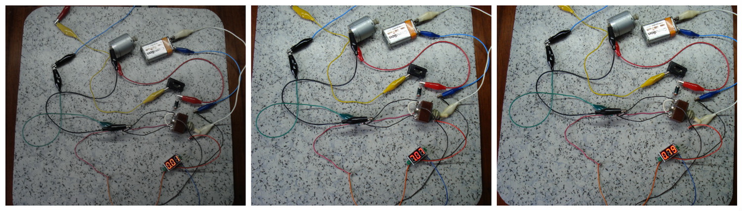
 And here there are more wires, although everything is simple:
» - an electric motor is connected with a pair of connecting wires« separate power supply for the voltmeter"- battery with two more wires
« power supply output"- a couple more wires
After power was supplied to the voltmeter, “0.01” was immediately displayed, after power was supplied to the electric motor, the meter in voltmeter mode showed a voltage at the output of the power supply equal to 7 volts, then switched to ammeter mode. Switching was performed when the power supply to the load was turned off. In the future, instead of a toggle switch, I will put a button without fixation, it is safer for the circuit and more convenient for operation. I was pleased that everything worked on the first try. However, the readings of the ammeter were different from the readings on the multimeter by more than 7 times.
 Chinese voltmeter - ammeter after alteration
 Here it turned out that the wire resistor instead of the recommended resistance of 0.08 ohms has 0.8 ohms. I made a mistake in the measurement during its manufacture in counting zeros. I got out of the situation like this: a crocodile with a negative wire from the load (both black) moved along a straightened nichrome spiral towards the input from the power supply, the moment when the readings of the multimeter and the now modified ampervoltmeter coincided and became the moment of truth. The resistance of the involved section of the nichrome wire was 0.21 Ohm (measured with a prefix to the multimeter at the limit of "2 Ohm"). So it didn’t even turn out badly that instead of 0.08, the resistor turned out to be 0.8 ohms. No matter how you count, according to the formulas, you still have to adjust. For clarity, the result of his efforts was recorded on a video.
Video
I consider the acquisition of these voltmeters successful, but it’s a pity that their current price in that store has grown a lot, almost $ 3 apiece. Written by Babay from Barnaula.
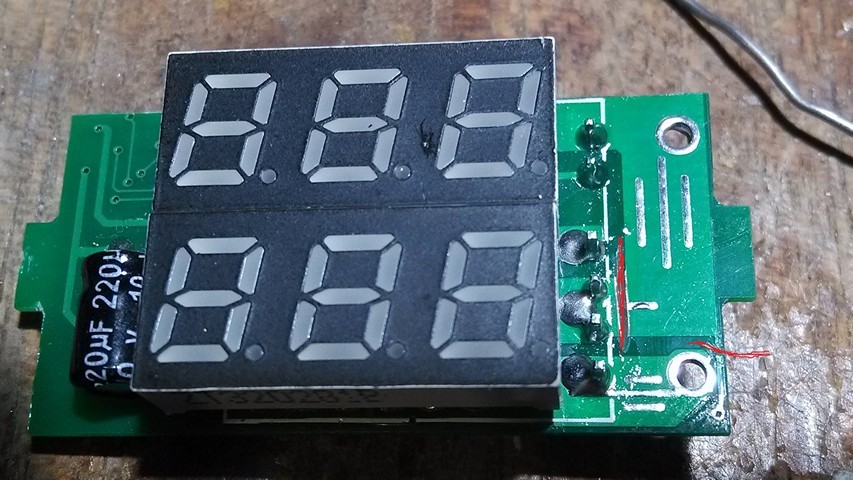
For my next project (converting an ATX PSU 580W into a laboratory one), I bought the above indicator. Not immediately and not in time it turned out that his power input is galvanically connected to the minus input of the shunt. This introduces a noticeable error when the indicator is powered from the same source from which the current is measured (error up to an ampere with my 50A shunt!). It was possible, of course, to pile up another duty room and power the indicator from it, but it seemed to me too bold and I decided to crack the indicator itself.
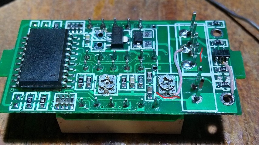
Searching the Internet I found his twin brother YB27VA and his typical circuit. I must say right away that the circuit of my device is slightly different. The essence of the alteration is to untie the differential input operational amplifier ad8605 (labeled as B3A) from the common power wire. Rework will require initial skills in reverse engineering (to make sure that the circuit is the same), soldering small parts and knowledge of Ohm's law :)
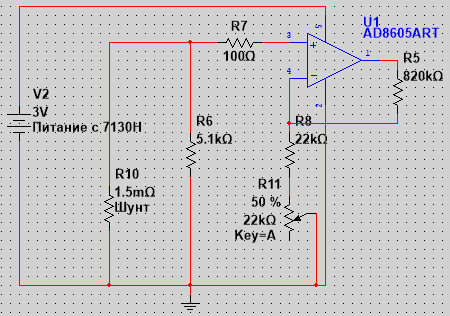
Schematic before modification:
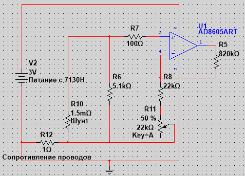
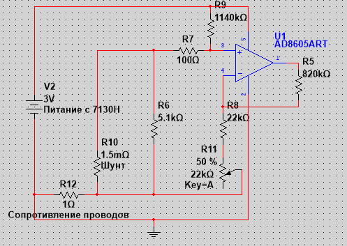
Scheme after:
Cut tracks are marked in red. I decided to abandon the resistor R6, since it seems that it is needed only so that the ammeter shows “0” when the shunt is off. Also, transferring power to the ad8605 (2 legs) is not necessary (judging by the tests in the simulator).
The second alteration solves the problem associated with the fact that the indicator does not “see” the first ~ 180mA of current, that is, when 1A is applied to the shunt, the device shows 0.8A, if 0.2 is applied, then zero, etc. This is due to the offset of the input of the op-amp and the ADC. It can be calculated by knowing the resistance of the shunt and the amount by which the device "lies". I got 270uV at the input of the op-amp. This offset is easy to create artificially by adding one resistor to the circuit, as a result, the device will begin to measure from zero.
In my case, it was necessary to add a 1140kΩ resistor from the 3V integral stabilizer to the "+" input of the op-amp. This resistor, together with R7 and the shunt, forms a divider that sets the initial offset.

The composite resistor turned out exactly as much as needed, due to the error of one of them :)
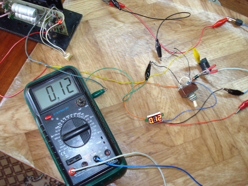
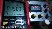
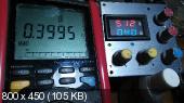
As a result, it now measures from 50mA up to 50A in minimum increments of approximately 20mA (0 also shows). Linearity also did not let us down, but sometimes it skips one, for example, it jumps from 0.12 immediately to 0.14.
The achieved accuracy pleasantly surprised me, it turned out to be a real measuring device that can be used in a laboratory PSU as the main indicator. Which you can even trust :) (this applies, at least, to the current). It is not clear why the Chinese decided to save on a couple of cheap parts. Their cost is clearly an order of magnitude lower than other components, the same ad8605, for example. Use good tools :)
More photos with measurements:


P.S. I already wanted to publish an article, but I decided to check - but how are things going with tension? It turned out that things are not good either - the device is lying at 0.1V, and it cannot be fixed elegantly, because the lower resistor is a tuning resistor. But I still soldered a 20MΩ resistor there and the result suited me)
I have already done a couple of reviews of a similar thing (see photo). I ordered those devices not for myself, for friends. A handy device for homemade charging, and not only. I also envied and decided to order already for myself. I ordered not only a voltammeter, but also the cheapest voltmeter. I decided to assemble a power supply for my homemade products. Which of them to put was determined only after I assembled the product completely. Surely there will be people who are interested.
Ordered November 11th. There was a small discount. Even though the price is low.
The parcel went for more than two months. The seller gave the left track from Wedo Express. But still the package arrived and everything works. Formally, there are no complaints.
Since it was this device that I decided to implant in my power supply, I’ll tell you a little more about it.
The device came in a standard plastic bag, “bubbled” from the inside. 
The item is currently unavailable. But this is not critical. Ali now has a lot of offers from sellers with good rating. Moreover, the price is steadily decreasing.
The device was additionally sealed in an antistatic bag. 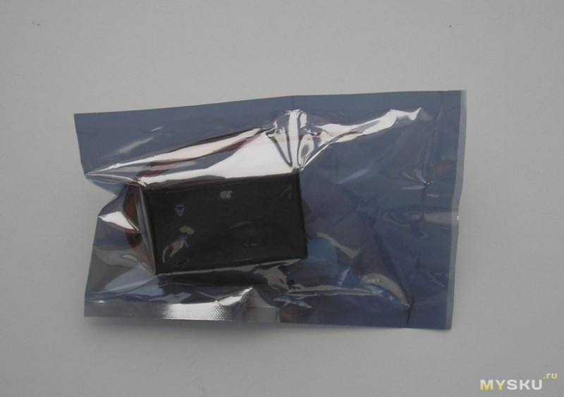
Inside the actual device and wires with connectors. 
Key connectors. On the contrary, do not insert. 
The sizes are just tiny. 
We look at what is written on the seller's page. 
My translation with corrections:
- Measured voltage: 0-100V
- Circuit supply voltage: 4.5-30V
- Minimum resolution (V): 0.01V
- Consumption current: 15mA
- Measured current: 0.03-10A
- Minimum resolution (A): 0.01A
Everything is the same, but very briefly, on the side of the product. 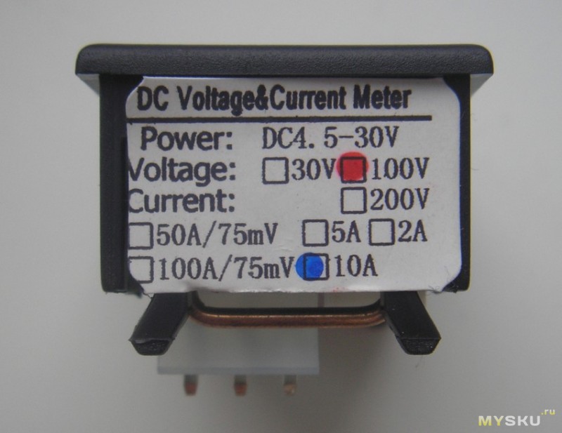
I immediately took it apart and noticed that minor details were missing. 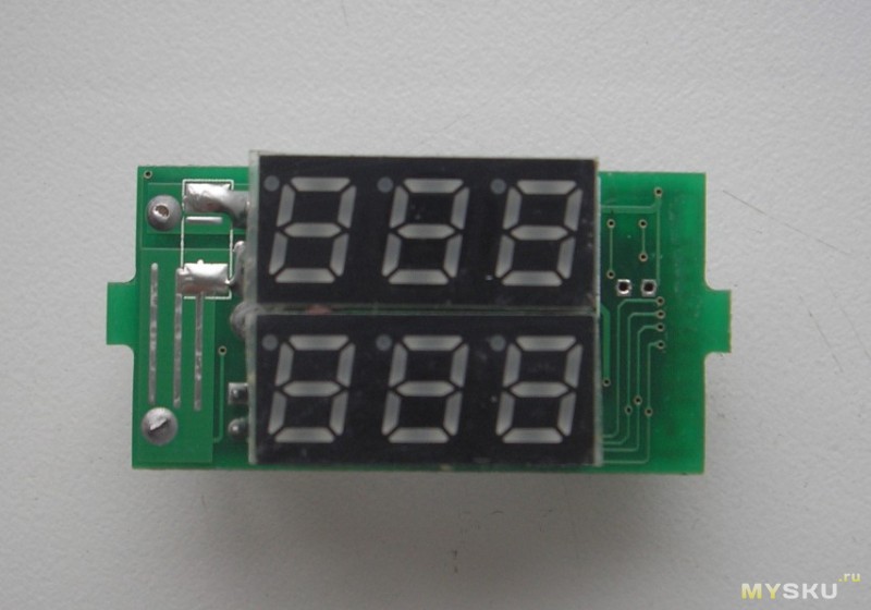
But in the previous modules, this place was occupied by a capacitor. 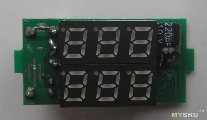
But their price was also different.
All modules look like twin brothers. Connection experience is also available. The small connector is designed to power the circuit. By the way, at a voltage below 4V, the blue indicator becomes almost invisible. Therefore, we follow technical specifications devices, less than 4.5V do not serve. If you want to use this device to measure voltages below 4V, you need to power the circuit from a separate source through a "connector with thin wires."
The current consumption of the device is 15mA (when powered by 9V "crown").
Connector with three thick wires - measuring. 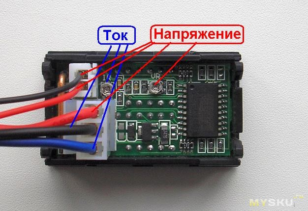
There are two accuracy controls (IR and VR). Everything is clear in the photo. Resistors are dark. Therefore, I do not recommend twisting it often (you will break it). The red wires are the leads for voltage, the blue ones are for current, the black ones are “common” (connected to each other). The colors of the wires correspond to the color of the glow of the indicator, do not get confused.
The head chip is unnamed. It once was, but it was destroyed. 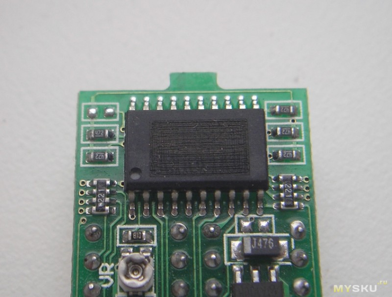
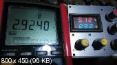
And now I will check the accuracy of the readings using the exemplary installation P320. I applied calibrated voltages 2V, 5V, 10V, 12V 20V, 30V to the input. Initially, the device underestimated by one tenth of a volt at certain limits. The error is insignificant. But I adjusted myself. 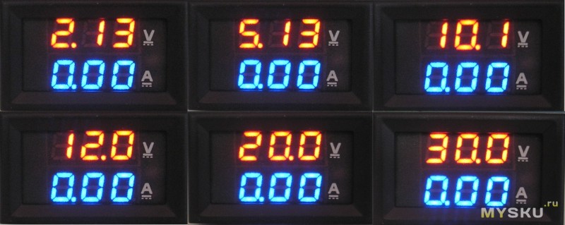
It can be seen that it shows almost perfectly. Adjusted the right resistor (VR). When the trimmer is rotated clockwise, it adds, when rotated counterclockwise, it decreases the reading.
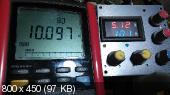
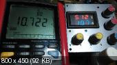
Now I'll see how it measures the current strength. I power the circuit from 9V (separately) and supply an exemplary current from the P321 installation 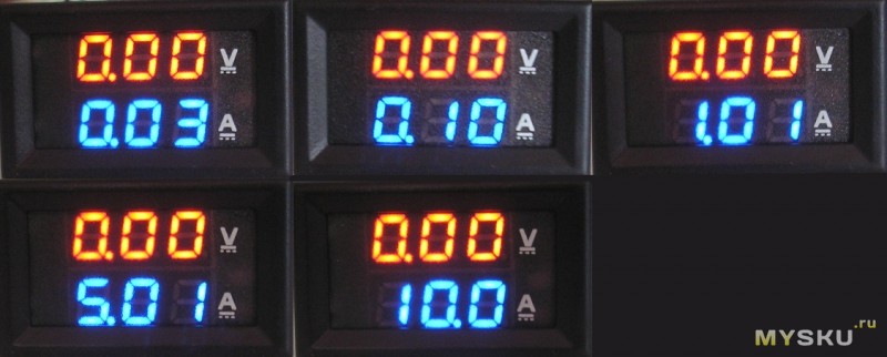
The minimum threshold from which it starts to correctly measure the current is 30mA.
As you can see, the current measures quite accurately, so I won’t turn the adjusting resistor. The device measures correctly even at currents greater than 10A, but the shunt starts to heat up. Most likely, the current limit is for this reason. 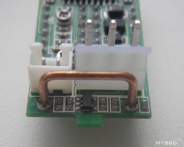
At a current of 10A, I also do not recommend driving for a long time.
More detailed calibration results are summarized in a table. 
I liked the instrument. But there are shortcomings.
1. The inscriptions V and A are painted, so they will not be visible in the dark.
2. The instrument measures current in one direction only.
I would like to draw attention to the fact that it would seem that the same devices, but from different sellers, can be fundamentally different from each other. Be careful.
On their pages, sellers often publish incorrect connection diagrams. In this case, there are no complaints. That's just a little of it (scheme) changed to a more understandable eye. 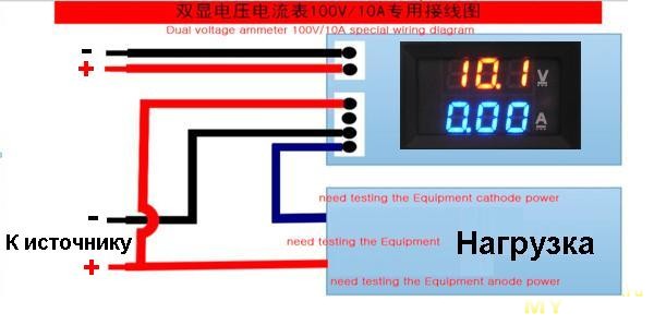
With this device, in my opinion, everything is clear. Now I'll tell you about the second device, about the voltmeter.
I ordered on the same day, but from a different seller:
Bought for US $1.19. Even with today's exchange rate - funny money. Since in the end I did not install this device, I will go through it briefly. With the same dimensions, the numbers are much larger, which is natural. 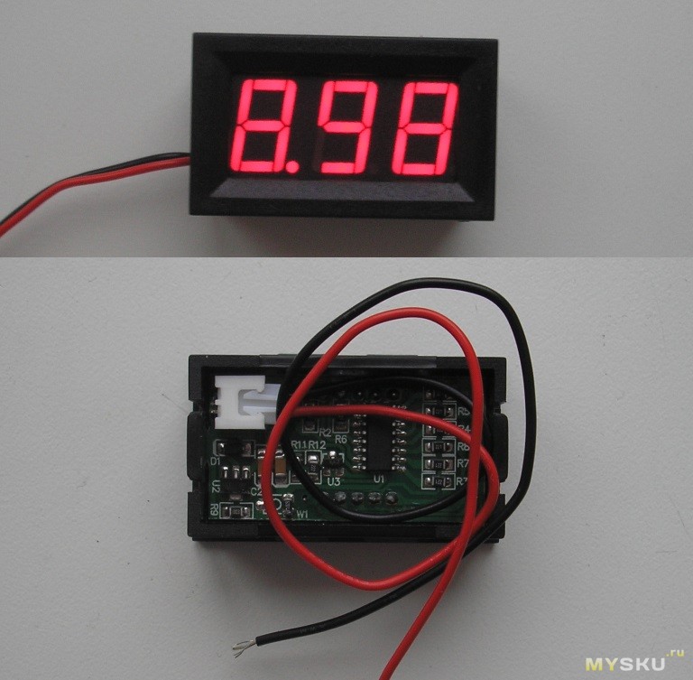
This device does not have a single tuning element. Therefore, you can only use it in the form in which it was sent. Let's hope for Chinese good faith. But I'll check.
The installation is the same P320. 
More details in the form of a table. 
Although this voltmeter turned out to be several times cheaper than a voltammeter, its functionality did not suit me. It does not measure current. And the supply voltage is combined with the measuring circuits. Therefore, it does not measure below 2.6V.
Both devices are exactly the same size. Therefore, replacing one with another in your homemade product is a matter of minutes. 
I decided to assemble the power supply on a more universal voltammeter. The devices are inexpensive. There is no burden on the budget. The voltmeter is still in stock. The main thing is that the device is good, and there will always be an application. Just from the store and got the missing components for the power supply.
I have been idle for several years now with such a set of homemade. 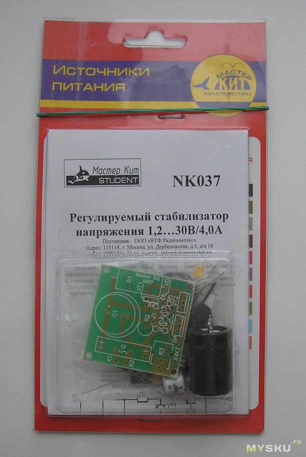
The scheme is simple but reliable. 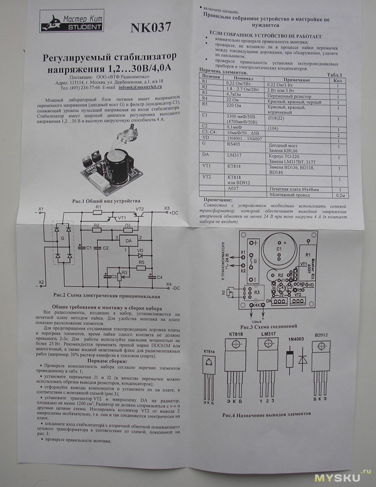
It is pointless to check the completeness, a lot of time has passed, it is too late to make claims. But everything seems to be in place. 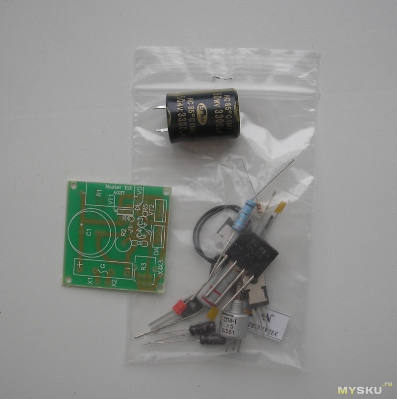
The trimmer resistor (complete) is too dumb. I see no point in using it. Everything else will fit.
I know all the disadvantages of linear stabilizers. I have neither the time, nor the desire, nor the opportunity to fence something more worthy. If you need a more powerful power supply with high efficiency, then I'll think about it. Until then, what has been done.
First I soldered the stabilizer board.
I found a suitable case at work.
I rewound the secondary of the torroidal trance to 25V. 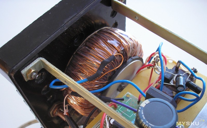
Picked up a powerful radiator for the transistor. All this stuffed into the body.
But one of the most important elements circuit is a variable resistor. I took a multi-turn type SP5-39B. The output voltage accuracy is the highest. 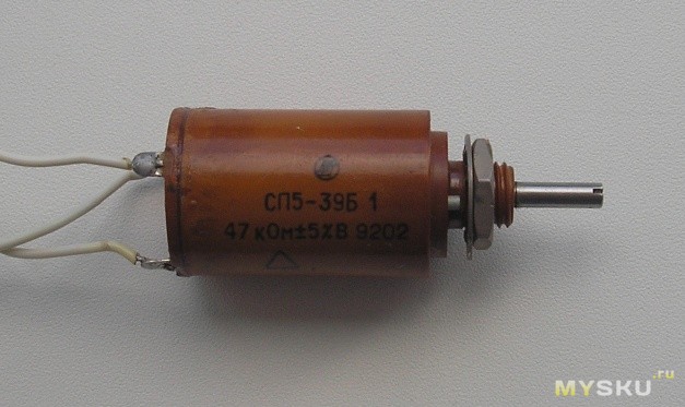
Here's what happened. 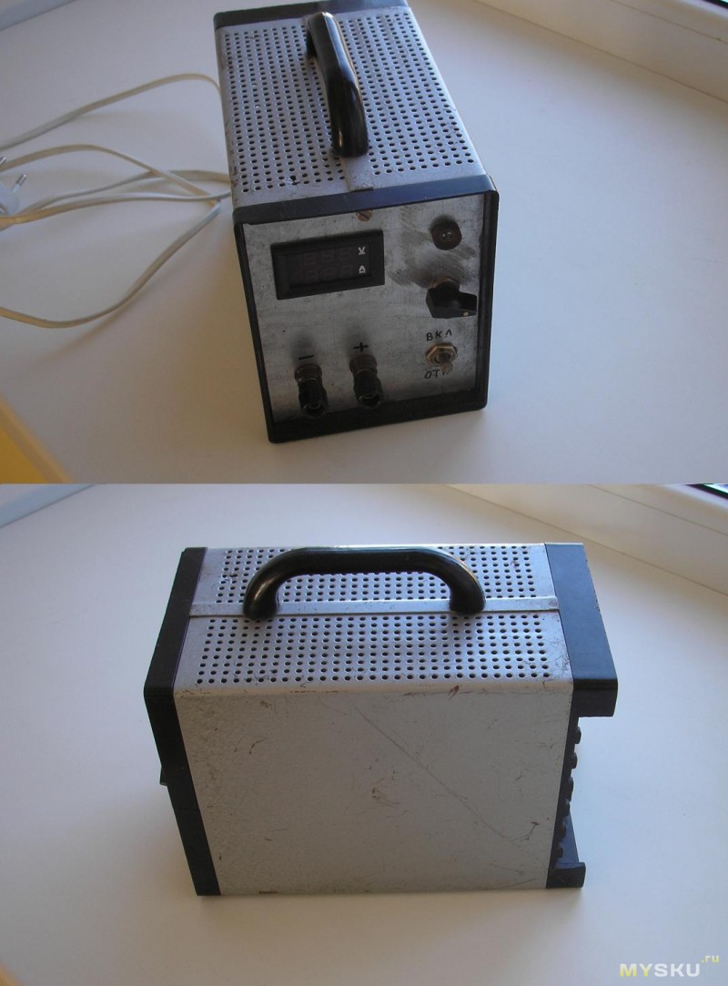
A little unsightly, but the main task is completed. I protected all electrical parts from myself, I also protected myself from electrical parts :)
It remains to "retouch" a little. I will paint the case from a spray can and make the front panel more attractive.
That's all. Good luck!