Selection of an I-beam according to the load. Bearing capacity of a single-span metal beam with a uniformly distributed load and hinged fastening on supports
MINISTRY OF SCIENCE AND EDUCATION OF THE RUSSIAN FEDERATION
FGBOU VPO "STATE UNIVERSITY-UNPK"
ARCHITECTURAL AND CONSTRUCTION INSTITUTE
Department: "Architecture"
Discipline: "Fundamentals of architecture
and building structures"
Settlement and graphic work
"Calculation of wooden, metal, reinforced concrete floors"
Performed:
Student gr. 41-AD
Kulikova A.V.
Checked:
Gvozkov P. A.
Calculation of a wooden floor
Pick up a section wooden beam to cover a residential building. Load on 1m 2 floors q n (trans) \u003d 1.8 kPa, q n \u003d 2.34 kPa,. The distance between the walls is 5 m. The scheme and plan are shown in Figure 1. The step of the beams is a = 1400mm.

1. We preliminarily accept the own weight of one meter of the beam q n beams \u003d 0.25 kN / m; 
 f=1.1
f=1.1
q beams = q n beams * f =0.25*1.1=0.275kN/m;
2. We collect the load per linear meter of the beam, taking into account its own weight:
q n \u003d q n floors * l gr + q n beams \u003d 1.8 * 1.4 + 0.275 \u003d 2.77 kN / m;
q \u003d q overlap * l gr + q beams \u003d 2.34 * 1.2 + 0.275 \u003d 3.083 kN / m.
Taking into account the reliability factor for liability n \u003d 1 (for a residential building) the calculated load per linear meter of the beam is q \u003d 3.083 kN / m.
3. Estimated beam length l 0 =5000-40-180/-180/2=4780mm.
4. Determine the maximum values of the transverse force and bending moment:
Q=ql 0 /2=3.083*4.78/2=7.37kN;
M= ql 0 2 /8=3.083*4.78 2/8=8.81kN*m.
5. We accept Siberian cedar wood species; grade 2; temperature and humidity operating conditions - A2, operating conditions coefficient tin= 1,0 (see Table 1.5 of SNiP P-25-80); we first assume that the dimensions of the section will be more than 13 cm, and determine the calculated bending resistance R and \u003d 15 MPa \u003d 1.5 kN / cm 2; design chipping resistance Rsk \u003d 1.6 MPa \u003d 0.16 kN / cm 2 (Table 2.4); according to the table 2.5 we determine the transition coefficient from pine wood, spruce to cedar wood m p \u003d 0.9.
The calculated resistances, taking into account the coefficient m p, are equal to:
R and \u003d 15 * 0.9 \u003d 13.5 MPa \u003d 1.35 kN / cm²
R sk \u003d 1.6 * 0.9 \u003d 1.44 MPa \u003d 0.144 kN / cm²
6. Determine the required moment of resistance
W x \u003d M / R and \u003d 881 / 1.35 \u003d 652.6 cm 3
7. Having accepted the beam width b = 15 cm, we determine the required beam height:
h=  =
= =16.15cm
We accept the cross section of the beam, taking into account the dimensions recommended by the assortment of lumber: b = 15 cm; h=19cm
8. We check the accepted section :
a) determine the actual values: the moment of resistance, the static moment of inertia and the moment of inertia of the beam:
W x \u003d bh 2 / 6 \u003d 15 * 19 2 / 6 \u003d 902.5 cm 3
S x \u003d 0.5bhh / 4 \u003d 676.88cm 3
I x \u003d bh 3 / 12 \u003d 15 * 19 3 / 12 \u003d 8573.75 cm 4
b) we check the strength by normal stresses:
c) checking the strength by shear stresses: Strength for normal and tangential stresses is provided; d) check deflections: To check deflections, you need to know the modulus of elasticity of wood along the fibers: E= 10 LLC MPa \u003d 1000 kN / cm 2; deflection according to design requirements is determined from the action of the entire normative load acting on the beam,
q n \u003d 0; 0277 kN / cm We determine the deflection according to the design requirements: f=5q n l 0 4 /384EI x =5*0.0277*478 4 /384*1000*8573.75=2.196cm limit deflection according to design requirements f u =
l/150 = 500/150 = 3.3 cm; f=2.196cm< f u
=3,3 см - прогиб балки в пределах нормы; Deflection according to aesthetic and psychological requirements determines - from the action of a long-term load (permanent and temporary long load) q l n =q n floors *l gr -p n l gr +p l n l gr + q n beams = 1.8*1.4-1.5*1.4+0.3*1.4+0.25=1.09kN/m f=5q n l 0 4 /384EI x =5*0.0109*478 4/384*1000*8573.75=0.86cm The maximum deflection is determined taking into account interpolation, for a bucket length of 5 m f u = l/183 = 500/183 = 2.73 cm. f=0.86 cm Conclusion: We accept a beam with a section of 15x19 cm from Siberian cedar, second-grade wood Calculation of a metal floor beam. According to the previous calculation, calculate a floor beam made of a rolled I-beam. It is assumed that the beam rests on a pilaster and a steel column. We collect the load on the beam from the cargo area with a length l gr \u003d 1.4 m. Load per square meter of overlap q n overlap = 11.8 kPa; q overlap = 15.34 kPa. The own weight of a running meter of a beam is approximately accepted q n beams = 0.50 kN / m; q beams = q n beams Scheme of supporting a beam on a pilaster and a steel column; l ef - estimated length of the beam (distance from the center of the beam support platform on the left support to the center of the support platform on the right support) 1. We determine the load acting on the running meter of the beam: o standard load q n \u003d q n floors * l gr + q n beams \u003d 17.02 kN / m \u003d 0.1702 kN / cm; normative long-term load - the full value of the temporary load on the floor of the trading floors p p \u003d 4.0 kPa, reduced value, which is a temporary long-term load, p l n \u003d 1.4 kPa: q l n \u003d q n -p n l gr + p l n l gr \u003d 17.02-4 * 1.4 + 1.4 * 1.4 \u003d 13.38 kN / m \u003d 00.1338 kN / cm; q \u003d q floors * l gr + q beams \u003d 15.34 * 1.4 + 0.53 \u003d 22.01 kN / m; design load, taking into account the reliability factor for liability
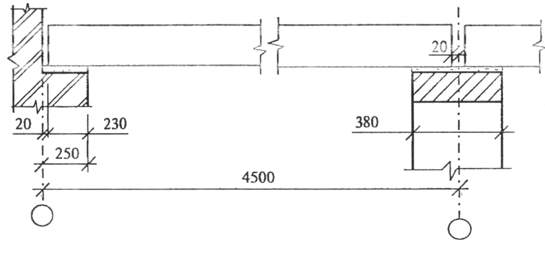
2. We preliminarily take the dimensions of the support plate and the support rib of the beam and determine its estimated length: l ef \u003d l- 85 - 126 \u003d 4500 - 85 - 126 \u003d 4289 mm \u003d 4.29 m. 3. Install the calculation scheme (Fig.) and determine the maximum transverse force and maximum moment. Q=ql ef /2=20.91*4.29/2=44.85kN M= ql ef 2 /8=20.91*4.29 2/8=48.1kN*m 4. According to the table. 50* SNiP II-23-81* determine the group of structures to which the beam belongs, and set steel: group of structures - 2; we accept steel C245 from steels acceptable for use. The calculated resistance of steel according to the yield strength (taking into account that the beam is made of shaped steel and having previously taken a thickness of rolled up to 20 mm) R y \u003d 240 MPa \u003d 24.0 kN / cm 2 (Table 2.2). Working condition coefficient y c = 0.9. 5, Determine the required modulus of the beam W x: W x \u003d M / R y y c \u003d 48.1 / (24 * 0.9) \u003d 2.23 * 100 \u003d 223 cm 3 6. According to the assortment, we accept an I-beam 20 Sh1, which has a moment of resistance close to the required one. We write out the characteristics of the I-beam: W x \u003d 275 cm 3; I X \u003d 826 cm 4;
S x
=
153 cm 3; wall thickness t= 9 mm; height h=193 mm; width
b =
150 mm; the mass of 1 m of length is 30.64 kg/m, which is close to the originally accepted one - we leave the loads unchanged. 7. We check the strength for shear stresses Rs R y -calculated shear resistance); Since reinforced concrete slabs are supported on the upper chord, which keep the beam from buckling, we do not calculate the total buckling. There are also no concentrated forces, therefore, it is not necessary to check local stresses. 8. Check the stiffness of the beam: ultimate deflection
according to aesthetic and psychological requirements
is determined depending on the length of the element by interpolation (the maximum deflection for a beam 4.5 m long is between the values of deflections for beams 3 m and 6 m long and is equal to: f and = l/175=429/175=2.45 cm); ultimate deflection according to design requirements f u = l/150 = 429/150 = 2.86 cm. The modulus of elasticity of steel E \u003d 2.06-10 5 MPa \u003d 2.06 * 10 4 kN / cm 2. The value of the deflection in accordance with the aesthetic and psychological requirements is determined from the action of the normative long-term load q l n = 0.1338 kN/cm: f=5q l n l ef 4 / 384EI x \u003d 5 * 0.1338 * 429 ^ 4 / (384 * 2.06 * 10 ^ 4 * 826) \u003d 1.08 cm deflection according to design requirements is determined from the entire standard load q n \u003d 0.1702 kN / cm: f=5qn l ef 4 / 384EI x \u003d 5 * 0.1702 * 429 ^ 4 / (384 * 2.06 * 10 ^ 4 * 826) \u003d 0.847 cm f=1.08cm Beam deflections according to aesthetic, psychological and structural requirements are within the normal range. Deflections according to technological requirements are not considered, since there is no movement of technological transport along the overlap. Consideration of deflections according to physiological requirements is beyond the scope of our course. Conclusion: we finally accept an I-beam 20 Sh1 for the manufacture of a beam that meets the requirements of strength and rigidity. Calculation of reinforced concrete floor. The reinforced concrete floor is affected by the load qneр=13.4 per 1m 2 . determine the required reinforcement area. Beam material heavy concrete class B35, longitudinal working reinforcement class A-III, section see fig. Beam support scheme Solution 1. We collect the load per 1 linear meter of the beam: overlap q = 11.8 kPa; load per 1 m from the own weight of the beam (specific gravity of reinforced concrete load per 1 m beam, taking into account its own weight with a length cargo area l gr = 1.4m: q \u003d q overlap *l gr + q beams \u003d 11.8 * 1.4 + 5.7 \u003d 22.22 kN / m; taking into account the reliability factor for liability 2. Determine the estimated length of the beam: l 0 =l-
40-l op / 2
-
l op / 2
\u003d 4500-40-230 / 2- 170 / 2 \u003d 4260 mm \u003d 4.26 m. 3, We carry out a static calculation (we build a calculation scheme, determine diagrams
Q
,
M
and find the maximum values of transverse forces and moment Q=ql 0 /2=21.11*4.26/2=44.96kN M= ql 0 2 /8=21.11*4.26 2/8=47.89kN*m. 4. We ask for materials: we accept heavy concrete, heat-treated at atmospheric pressure during hardening, compressive strength class B35, y b 2 \u003d 0.9; hot-rolled rod fittings of class A-III. We write out the strength and deformation characteristics of materials: R
b
=
19.5 MPa;
R bt =
1.30 MPa; Eb \u003d 34.5 * 10 3 MPa; R s = 365 MPa; R SW = 285 MPa; E s \u003d 20 * 10 4 MPa. Design scheme and diagrams 5. Set the distance from the center of gravity of the reinforcement to the extreme stretched concrete fiber a and determine the working height of the beam A 0: take a = 5.0 cm; h 0 \u003d h- a \u003d 60-5 \u003d 55 cm. 6. Find the value of the coefficient A 0: A 0 \u003d M / R b 7. We check that the value of the coefficient A 0 is not more than the boundary value A 0R; A 0 \u003d 0.03< А 0R
= 0,425. 8. 9. Find the required reinforcement area: A s =M/ We accept 6 rods with a diameter of 8mm. 10. Check the percentage of reinforcement of the beam: The percentage of reinforcement is greater than the minimum, equal to 0.05%. 11. We determine the mounting fittings: A"
s\u003d 0.1 A s \u003d 0.302 cm 2 ,
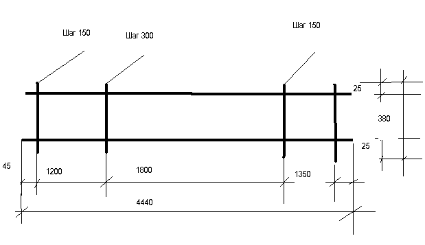
accept 1 rod with a diameter of 8mm; 12. Determine the diameter of the transverse rods: d sw> 0.25ds=0.25*8=2mm We accept transverse rods with a diameter of 3 A-III, A sw = 0.071 cm 2 (ar- beam cross-section - see fig.) Beam section reinforcement 13. We construct the frame of the beam: determine the length of the supporting sections 1/4
l= 1/4 4500 = 1125 mm; determine the required step of the transverse rods on the supporting sections
s
= h/2=300mm, which is more than 150 mm; we take the step of the rods s = 150 mm; determine the step of the transverse rods in the middle of the beam s = 3/4 h = 450 mm, which is less than 500 mm; accept a step of 300 mm; when designing the frame, the dimensions of the support sections are slightly changed so that they are a multiple of the accepted steps of the transverse rods. Beam section reinforcement 14. Check the condition: Q We check whether the transverse force of the transverse force that is perceived by concrete is greater or less: Q \u003d 44.96 kN Conclusion: We carry out a reinforced concrete floor beam with a section of 350x600mm, we reinforce according to the calculation. 1. For example, we used 4 profile pipes with a section of 100x100 mm with a wall thickness of 5 mm as beams for covering a room measuring 4 by 6 meters. Then the span length of the beam will be l = 4 m, and the pitch of the beams is 6/5 = 1.2 m. According to the assortment for square profile pipes, the moment of resistance of such a metal beam will be Wz \u003d 54.19 cm 3. 2. The design resistance of steel should be checked with the manufacturer, but if it is not known exactly, then the smallest possible one can be taken, i.e. R \u003d 2000 kg / cm 2. 3. Then the maximum bending moment that such a beam can withstand: M = W z R = 54.19 2000 = 108380 kgcm or 1083.8 kgm. 4. With a span of 4 m, the maximum distributed load per linear meter is: q = 8M/l 2 = 8 1083.8/4 2 = 541.9 kg/m. 5. With a beam spacing of 1.2 m (the distance between the axes of the beams), the maximum flat uniformly distributed load per square meter will be: q \u003d 541.9 / 1.2 \u003d 451.6 kg / m 2(this includes the weight of the beams). That's the whole calculation. If logs are first laid on top of the metal floor beams, and then the overlap is already made along the logs, then not one uniformly distributed load, but several concentrated ones, will act on such metal beams. However, it is not at all difficult to convert concentrated loads into equivalent uniformly distributed loads - it is enough to simply divide the value of the uniformly distributed load, which we have already determined, by the conversion factor. For example, if we laid logs on metal beams every 0.5 meters, then there are only 4 / 0.5 +1 = 9 logs - concentrated loads. In this case, extreme lags can be generally ignored, and then the number of concentrated forces will be = 7, and the coefficient of transition from concentrated loads to an equivalent uniformly distributed load will be γ = 1.142. Then the maximum uniformly distributed load that this metal beam can withstand is: q \u003d 451.6 / 1.142 \u003d 395.4 kg / m 2 Of course, metal beams can be multi-span or have a rigid fixation on one or two supports, i.e. be statically indeterminate. In such cases, only the formula for determining the maximum bending moment will change (see design schemes for statically indeterminate beams), but the entire calculation algorithm will remain the same. Overlappings in the construction of low-rise buildings are:
?
Wooden on wooden or metal beams; ?
Monolithic reinforced concrete on metal beams; ?
Prefabricated reinforced concrete floor slabs (since they are laid without calculation, there will be no further consideration of it). E
Calculation elements for overlapping:
?
Floor slab; ?
Cantilever bearing beams (have one support in the wall, for balconies); ?
Supporting load-bearing blocks (beams rest on load-bearing walls with their ends, ceiling between floors and attic). For wooden floors
beams in the form of a wooden bar or log are used as load-bearing beams. As well as metal beams in the form of rolled profiles, such as an I-beam, a channel, a corner. As a floor slab, which relies on load-bearing beams, flooring or filing from boards is used. For monolithic reinforced concrete floors
as load-bearing beams, metal beams are used in the form of rolled profiles, such as an I-beam, a channel, a corner. A monolithic reinforced concrete slab serves as a floor slab, which is supported by load-bearing beams. Wooden floor beam
are the most economical option. They are easy to manufacture and install, have low thermal conductivity compared to steel or reinforced concrete beams. The disadvantages of wooden beams are lower mechanical strength, requiring large sections, low fire resistance and resistance to damage by microorganisms. Therefore, wooden floor beams must be carefully treated with antiseptics and fire retardants.The optimal span for wooden beams is 2.5-4 meters. The best section for a wooden beam is rectangular with a height to width ratio of 1.4:1. The beams are led into the wall by at least 12 cm and waterproofed in a circle, except for the end. It is better to fix the beam with an anchor embedded in the wall.When choosing a section of floor beams, the load of its own weight is taken into account, which for beams of interfloor ceilings, as a rule, is 190-220 kg / m? , and the temporary load (operational), its value is taken equal to 200 kg / m? . Floor beams are laid along a short section of the span. It is recommended to choose the installation step of wooden beams equal to the installation step of the frame racks.Below are several tables with the values of the minimum sections of wooden beams for various loads and span lengths: Table of sections of wooden floor beams depending on the span and installation step, with a load of 400 kg / m?. - it is recommended to rely on this load If you do not use insulation or do not plan to load floors (for example, an uninhabited attic floor), then you can use the table for lower load values of wooden floor beams: Table of minimum sections of wooden floor beams depending on the span and load, with loads from 150 to 350 kg / m?
.
If you use round logs instead of rectangular beams, you can use the following table:The minimum allowable diameter of round logs used as floor beams depending on the span at a load of 400 kg per 1 m?
I-beam metal floor beam
has a number of advantages, only with one drawback - high cost. A metal I-beam can cover large spans with a significant load, a metal steel beam is not combustible and resistant to biological influences. However, a metal beam can corrode in the absence of a protective coating and the presence of aggressive environments in the room.In most cases, in amateur construction, when calculating, it should be assumed that the metal beam has hinged supports (that is, the ends are not rigidly fixed as in a steel frame structure). The load on the ceiling with steel I-beams, taking into account their own weight, should be calculated as 350 kg / m?
without screed and 500 with screed kg/m?
The step between the I-beams is recommended to be equal to 1 meter. In case of economy, it is possible to increase the step between the metal beams up to 1.2 meters.The table for selecting the number of an I-beam metal beam at different pitches and lengths of runs is shown below: 16
16
16
12
12
10
10
10
20
20
20
12
12
12
10
10
10
20
20
20
12
12
12
Reinforced concrete floor beams
When constructing reinforced concrete beams, the following rules must be used: 1. The height of the reinforced concrete beam must be at least 1/20 of the length of the opening. Divide the length of the opening by 20 and get the minimum height of the beam. For example, with an opening of 4 m, the height of the beam should be at least 0.2 m. 2. The width of the beam is calculated based on the ratio of 5 to 7 (5 - width, 7 - height). 3. The beam should be reinforced with at least 4 bars of reinforcement d12-14 (it can be thicker from below) - two at the top and bottom. 4. Concrete at one time, without interruptions, so that the previously laid portion of the mortar does not have time to seize before laying a new portion. Concreting beams with a concrete mixer is more convenient than ordering a mixer. The mixer is good for quickly pouring large volumes. \u003d M / W x \u003d 881 / 902.5 \u003d 0.98
  \u003d QS x / I x b \u003d 0.039 kN / cm 2 f = 1.05;f =1.05*0.50=0.53kN/mn=0.95.
 n=0.95
 :\u003d QS x / I x b \u003d 44.85 * 153 / 826 * 0.9 \u003d 2.87 kN / cm 2c = 0.58Ry c \u003d 0.58 * 24 * 0.9 \u003d 12.53 kN / cm 2 (R s \u003d 0.58= 1.12 kN/cm2< R s y c =
2,87 кН/см 2 ;
прочность обеспечена.
:\u003d QS x / I x b \u003d 44.85 * 153 / 826 * 0.9 \u003d 2.87 kN / cm 2c = 0.58Ry c \u003d 0.58 * 24 * 0.9 \u003d 12.53 kN / cm 2 (R s \u003d 0.58= 1.12 kN/cm2< R s y c =
2,87 кН/см 2 ;
прочность обеспечена.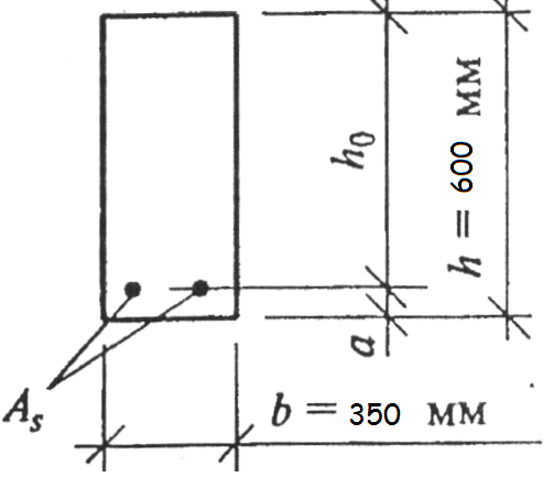
 = 25 kN/m 3) g beams =bh
  f =0.35*0.6*25*1.1=5.7kN/m;n \u003d 0.95q \u003d 22.22 * 0.95 \u003d 21.11 kN / m
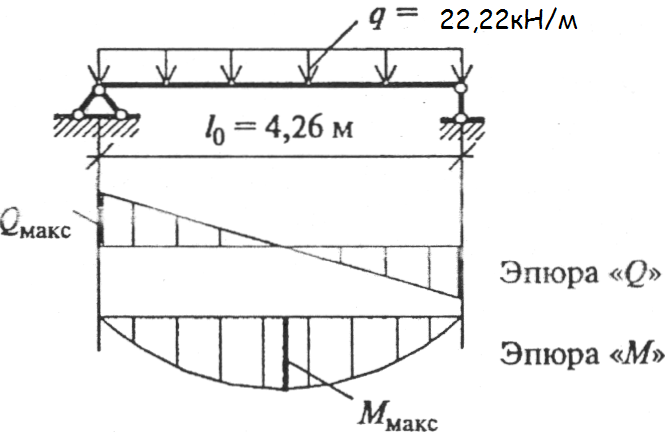 b 2 bh 0 2 \u003d 4789 / 1.95 * 0.9 * 35 * 55 2 \u003d 0.03
 =0.79h 0 R s \u003d 4789 / (0.79 * 55 * 36.5) \u003d 3.02 cm 2
 \u003d A s * 100 / bh 0 \u003d 30.2 * 100 / (35 * 55) \u003d 0.16%
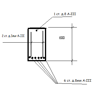
 Q b , min =
  b 3 (1+ f+ n)=R bt b 2 bh 0 \u003d 1.30 * 0.9 * 35 * 55 * 55 \u003d 147420N \u003d 147.42 kN,
Bearing capacity of a single-span metal beam under the action of concentrated loads and hinged on supports
Span / installation step (in meters)
2,0
2,5
3,0
4,0
4,5
5,0
6,0
0,6
75x100
75x150
75x200
100x200
100x200
125x200
150x225
1,0
75x150
100x150
100x175
125x200
150x200
150x225
175x250
Loads , kg/rm. m
Cross-section of beams with span length, meters
3,0
3,5
4,0
4,5
5,0
5,5
6,0
150
50x140
50x160
60x180
80x180
80x200
100x200
100x220
200
50x160
50x180
70x180
70x200
100x200
120x220
140x220
250
60x160
60x180
70x200
100x200
120x200
140x220
160x220
350
70x160
70x180
80x200
100x220
120x220
160x220
200x220
span widthin meters
Distance between logsin meters
Log diameterin centimeters
2
1
13
0,6
11
2,5
1
15
0,6
13
3
1
17
0,6
14
3,5
1
19
0,6
16
4
1
21
0,6
17
4,5
1
22
0,6
19
5
1
24
0,6
20
5,5
1
25
0,6
21
6
1
27
0,6
23
6,7
1
29
0,6
25
7
1
31
0,6
27
7,5
1
33
0,6
29
?
Span 6 m. No. I-beam at a step, mm
Span 4 m. No. I-beam at a step, mm
Span 3 m. No. I-beam at a step, mm
1000
1100
1200
1000
1100
1200
1000
1100
1200
300
10
400
500
10
121
12