A simple all-wave VHF-FM radio receiver. Easy tuning system for VHF FM receiver
http://pandia.ru/text/79/018/images/image003_61.jpg" width="646" height="327">
http://pandia.ru/text/79/018/images/image005_53.jpg" width="661" height="472 src=">
Achtung! Crooked translation from Chinese!
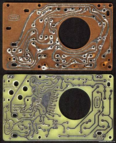
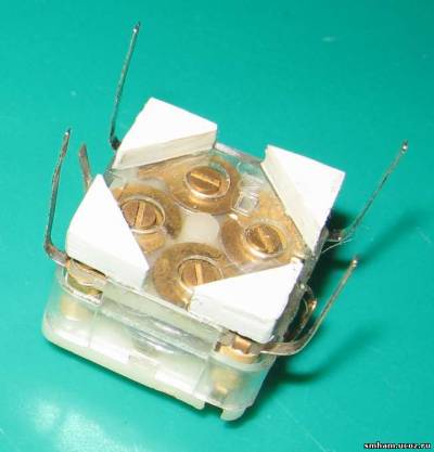
Scanner radio receiver 45-870MHz FM
It uses excellent art of all-TDQ-38 head, as well as the addition of high-frequency components of the finished product LA7533 box in place, hence the receiver's high sensitivity, stable performance and easy to produce. The machine can receive 45-870MHz frequency range of all signals, and can also be used to listen to FM radio, TV sound, as well as cordless phones and walkie-talkie signals, etc.; With audio and video signal output port, the monitor can support and become full -- Channel TV receivers, TVs can be repaired while the audio and video signal source.
Electronic circuits" href="/text/category/yelektronnie_shemi/" rel="bookmark">electronic conversion circuits and two LED LED1 respectively red, green, yellow three instructions. L-band frequency up to 45MHz ~ 150MHz, H paragraph frequency 142MHz ~ 380MHz, U frequencies above 375MHz ~ 870MHz.
In the case of using high frequency sensitivity, the first full added high quality product type, complete elimination of the overall low radio sensitivity, poor string selectivity and the issue of Taiwan. LA7533 box is used in production for IF 6.5MHz sound, pre-built in its place, on surface acoustic waves and put the LA7533 filter block; one line with 11 feet, in which to input PIN-IF ①, ② ground foot, 12V power supply pin ③, ⑥ feet to output audio, ⑦ pin voltage output 6.8V AGC, ⑩ feet to output video signal, which will be based on the housing.
Audio amplifier IC2 block model ULN2283B, if not just buy into the composition can be used on the LM386 audio amplifier circuit. Tuner 220KΩ potentiometer W1 selected color frequency tuning potentiometer, tuner 30V DC micro-instructions using the first table.
Radio receivers from 200MHz -> Receiver at 433MHz SAW stabilization from "Blaze"
http://*****/index. php? act=categories&CODE=article&article=1174
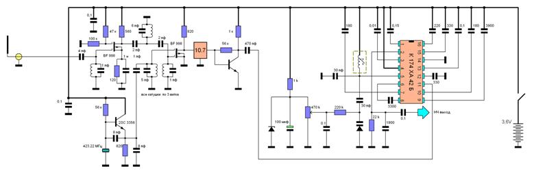
The HF part, developed by my fellow countryman, Mr. SHATUNO, I generally consider the best in the world. Next comes the piezo at 10.7 MHz (in principle, it is better to replace it with a single circuit, since the difference between the SAW frequencies can exceed its bandwidth). The circuit is also needed if it is not possible to buy resonators with a standard difference in the IF, for which there are industrial filters. The mixer transistor is loaded on its primary winding, and an amplifying stage on the transistor is connected to the secondary through a decoupling capacitance, or from the tap of this coil (as you like).
The receiver worked very well. Showed approximately 20% gain in distance in comparison with the scanner (I don’t remember the model of Motorola), apparently due to the fact that the antenna in the scanner is for all ranges at once. The setting is stable (like set and forget).
.
I made radio receivers for radio microphones according to similar schematics for various frequencies, only instead of XA42 I used the previously common XA34-I.
I can definitely say that the receiver deserves attention for its simplicity and normal characteristics. Sensitivity reaches 0.6-08 microvolts at WFM. In essence, this is a double frequency conversion receiver, the first IF is 10.7 MHz, the second is 75 kHz in a microcircuit. In addition, the microcircuit has an AFC and therefore the receiver normally keeps the signal frequency. The receiver in question is a single frequency receiver, since the presence of the specified IF filter with a given bandwidth will actually allow tuning within only 700 kHz. In order to slightly expand the tuning range, it is necessary to replace the IF filter with a circuit tuned to 10.7 MHz. In addition, the circuit must be shunted with a resistance of 47-56 com. to reduce the quality factor and increase the bandwidth, and even better, make the first IF by 30 meg. It should also be borne in mind that the applied field workers have a high input resistance and do not load the circuit, so they have a high quality factor and will require fairly accurate tuning to the frequency. The circuit connected to the local oscillator and cutting off its harmonics should not have inductive coupling with other contours
Hello Dear!
I'll try to clarify the situation with the receiver. The first (most offensive). I made this device myself and it works exactly as it says in the description.
You are absolutely right about the inconsistencies between the signet and the scheme. They do not quite match, because I have already made 6 of them and changed something all the time.
Ground capacitance is needed if a low-resistance antenna is used (the same if the antenna is turned on from the loop tap). Then I refused such an inclusion and built input circuit as in the diagram. They work in the same way, but in the version as in the diagram there is less hemorrhoids with the setting.
Back-to-back diodes at the input are not needed (they are inside the 998th).
The payment is one-sided. The screen only has a 10.7 MHz circuit.
Zener diode (sorry forgot to specify the voltage) at 2.2 volts. Its task is to keep the setting at the same level when the batteries are discharged.
The gate, on which the voltage divider, can be shunted to ground with a capacitance, or you can not do this (just in case, it is better to shunt).
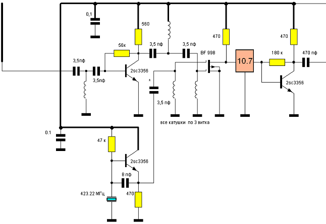
I didn't see the difference. The gates of the transistor are completely identical (they can be interchanged). The circuits have (except for 10.7 MHz) 3 turns of 0.67 wires with a diameter of 4 mm. The circuit, despite the lack of screening, is not prone to excitation. Instead of the 1st transistor, kt399a was tried - practically no difference.
Difficulties may arise with the local oscillator on the SAW. If he does not want to start, you need to play with 8 pF capacities up to throwing out the one that goes from the emitter to ground.
When setting up the 10.7 circuit, you need to be careful. Its setting despite
at a low frequency is very sharp. In the absence of a signal, it can hang around the bush (do not forget about APCG). This effect can be mistaken for instability.
In general, I did the following.
I made a bug at 433.9 MHz, but without a final stage and antenna, put it in an iron pan and took it away until the receiver starts to hiss.
I adjusted the receiver with 2 matches, moving the turns of the circuits until it stopped making noise. Then the pan was carried away even further and repeated all over again.
The antenna to the receiver, of course, was connected.
There were options when the capacitances of the input circuit and filter (6 pF) had to be removed completely.
The ULF is really LM386. A transistor is needed in front of it, because in a typical connection, the LM386 does not have enough amplification for normal volume, because the low-frequency level with XA42 is small.
In general, it is useful to put a low-pass filter (up to 4 kHz) on the op-amp before the ULF. The intelligibility of the signal will increase greatly.
The difference between XA42 instances should be taken into account (it can be significant specifically regarding sensitivity and BSHN)
Sincerely, BLAZE.
Well, this is how it will look like? Or what else to remove - to add?
What will we have then FC? How to install it?
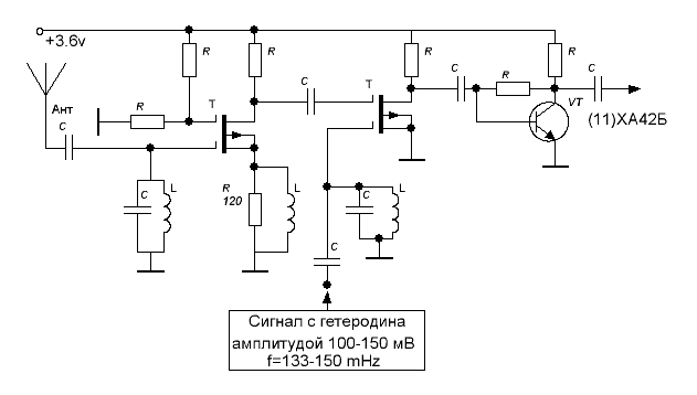
The signal from the local oscillator is approximately from 133 to 150 meg, since the subtraction of the IF at the 3rd harmonic is expected. Right?
Sori, if possible, where tupanul, because I'm just gaining knowledge in this topic.
Attached image
Blaze
Approximately it will look like this, only the circuit at the source of the first transistor is not needed (I think this is a typo) there should be a capacitance. By changing the IF you will tune to the frequency you need. IF is the absolute difference between the frequency of the input signal and the frequency of the local oscillator (or its harmonic). By IF, I meant the tuning frequency of the XA 42 local oscillator (it can be up to 150 MHz), here I do not take into account the microcircuit's own low IF.
One of the gates of the second transistor, the one to which the signal from the UHF is applied, must be connected through a 100 kΩ resistor to the minus power supply.
Those who wish to assemble the receiver in question must remember that it uses microwave field-effect transistors, the use of which provides undeniable advantages, but they are afraid of breakdown by static voltage and it is very likely that this may be one of the reasons for failure.
The normal circuit of the RF block for this frequency is also laid out on page 165 by G. Schreiber "400 new electronic circuits".
An attempt to use a local oscillator at 140-144 mega will not give a normal result, because there the local oscillator works with the AFC loop, output voltage the third harmonic is small, but it is fed to the base of a bipolar transistor, the conversion steepness of which is much higher than that of a field-effect transistor.
Another option
http://*****/index. php? showtopic=1981&st=0

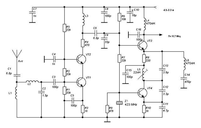
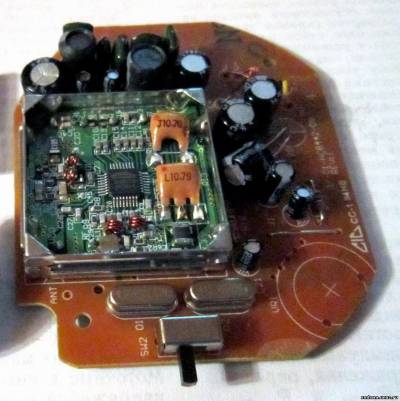
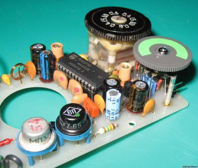
Yusik-san, one of the modest fellows of our portal, presented his own version of the Blaze receiver on XA42, or rather on the smd analogue of TDA7010. The circuit is supplemented with the RF function of the same Blaze, which indicates the dignity of the circuit in terms of repetition. Also, the circuit introduced control of the discharge of the battery and the possibility of recharging without removing the power source.
This version of the receiver is claimed to have a sensitivity of about 0.3 μV.
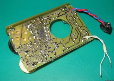
The printed circuit board is also included. Well, pictures over time ...
The principle of operation of the device.
The signal received by the antenna is amplified by the URF and, together with the local oscillator signal, is fed to the mixer. After the mixer, a rather complex “porridge” is obtained, consisting of F het,
F input signal and from their sum and difference plus harmonics.
We are interested in the difference frequency between F in signal and F het.
In one version of the circuit, the "porridge" of frequencies is passed through a low-pass filter and amplified by a two-stage pre-amplifier before reaching the input of the TDA 7000. In another version, there are no filters at all and the entire mixture of frequencies comes after the single-stage preamplifier to the input of the TDA 7000.
In fact, both versions of the circuit have approximately the same parameters regarding sensitivity, but in the circuit with a low-pass filter, less noise was observed when receiving equally weak radio transmitter signals.
The TDA 7000 operates as a standard ULF detector and a preliminary ULF.
Thanks to the built-in AFCG, a frequency deviation compression device, the TDA 7000 does its job quite well and produces a fairly high-quality and intelligible signal at its output. The low-pass filter is a chain of a 22 k resistor and a capacitance of 5600 pF in parallel with it.
The receiver behaves like a narrowband with a "high-speed APCG", due to which there is no distortion of the low-frequency signal at the output even if the frequency deviation from the transmitter is excessive.
Without special alterations, the receiver is capable of operating at 814.6 MHz, while you only need to double the natural frequency of the internal local oscillator of the microcircuit. The input circuit and the circuit at the mixer inlet can be left alone, but better results will be achieved if the RF circuit is reduced by 1 turn each.
Setting.
It is best to start setting up the receiver by checking the operation of the first local oscillator on the SAW.
Judging by the reviews, this often causes problems.
The best indicator of local oscillator performance is, of course, the reference receiver. If it is not there, you can use a wavemeter by connecting its antenna through 1 - 2 peaks to the output of the local oscillator.
Next, you should make sure that the generation reliably occurs starting from 2.7 -3 volts, and with a very smooth increase in the supply voltage. If the local oscillator starts up unreliably, it is advisable to choose a capacitance between the base and the emitter of the transistor (in most cases, you can not put it at all). Perhaps the emitter capacitance - mass will also need to be selected.
Installation requirements are the same as for any microwave devices. First of all, be careful! A significant role is played by the tinning of tracks and sections associated with a common bus or power plus. The fact is that copper oxidizes over time and its resistance to microwave becomes large, which can lead to incorrect operation of the device in the future.
The contact pads of the SAW resonator must be tinned before soldering to the board. The rivets connecting the sides of the board are made of thick (0.6 - 0.7 mm) cleared copper wire and flattened with pliers.
The next tuning stage is to “adjust” the frequency of the second (internal) local oscillator of the microcircuit itself to the desired IF (it is approximately equal to the modulus of the difference between the frequencies of the transmitter and the first local oscillator minus 75 kHz KHz is the second lowest IF (inside TDA 7
The low-pass filter (one of the receiver options) does not need to be tuned, however, it is wound on exactly the same ferrite core with a trimmer "cup" as the circuit of the second local oscillator and has the same number of turns with it. Both circuits were taken from obsolete VHF broadcasting receivers.
As reference signals during tuning, a very useful, in my opinion, device was used - a laboratory radio microphone for different frequencies.
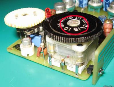
There is no point in dwelling on it in detail, since the photo shows that this is a standard circuit without an end stage and an antenna, designed specifically to “pull out” the sensitivity of the receiver during tuning.
Very carefully, you should choose a capacitance of 2.2 pF, connecting the input of the mixer with the output of the first local oscillator. The fact is that the local oscillator signal, if it is too strong, can make the receiver "deaf".
It is not necessary to screen input contras. They are adjusted to the maximum sensitivity of the receiver by compressing or stretching the coils.
Charger and battery status indication.
Apparently, there is no point in dwelling on these conveniences, since the principle of their operation is obvious from the circuit diagram of one of the receiver options.
The battery charging current, thanks to the stable current generator on the LM 317, is always constant and equal to I (out) \u003d 1.25 / R. R in the circuit is 18 ohms, while the charging current is about 70 mA..png" width="645" height="356">
Device PCB file.
Sergei (blaze)
Kremenchuk
*****@***net
*****@***com
ICQ
In addition to the article
I would like to add that there is no point in a two-stage UPCH. However, the second cascade does not interfere.
Today I tested the receiver on TDA 7021 (XA 34), I was very pleased.
Apparently there is no point in drawing a diagram (everything is clear from the board).
Simplest VHF FM receiver, available for repetition by a novice radio amateur, can be assembled according to the scheme of a single-transistor synchronous-phase detector. A schematic diagram of such a receiver is shown in the figure.
The signal is received by the WA 1 antenna, the role of which can be played by a piece of mounting wire. This signal enters the oscillatory circuit L1C2, by adjusting the capacitor C2, the circuit can be tuned within the VHF FM range of 65.8-73 MHz. The signal voltage allocated by this circuit is fed through the capacitor C3 to the base of the transistor VT1. This transistor stage performs several functions simultaneously: the functions of a phase detector, a low-pass filter, a DC amplifier, and a low-frequency amplifier. Phase detection occurs on p-n transitions transistor equivalent to diode junctions. You can assemble the receiver by volumetric installation, or you can develop a printed circuit board based on a circuit diagram, and arrange the parts on it in the same order as in the diagram. Coil L1 does not have a frame, for winding a drill shank with a diameter of 7 mm is taken and a coil is wound on it with a PEV wire of 0.4 ... 0.5 mm. Coil L1 contains 14 turns. After winding, the drill is removed from the coil (it only serves as a winding mandrel).
Transistor P416B can be replaced with GT308A, KT603B. Phone - any high-resistance small-sized. Capacitor C2 of the PDA type is ceramic, for 8 ... 30p, 5 ... 20p or 4 ... 15p, it is adjusted by turning the screw located in the middle. As a power source, you can use a Krona 9 V battery. Any switch, for example, a toggle switch.
Setting relatively simple. You need to connect the phone, power and antenna - a piece of mounting wire, the longer the better. It is advisable to hang the antenna out the window or hang it on window frame. Now you need to put on the headphones (they should have a slight hiss) and by rotating the rotor of the capacitor C2 try to catch one station. If this does not work, you need to stretch the turns of the coil a little and repeat.
Good results from such simple receiver not achieve, but it can receive two or three stations in the VHF FM band. Experiment with stretching and compressing the turns of the L1 coil, the length and location of the antenna, and the supply voltage. Instead of headphones, you can connect a 1 ... 3 kOhm resistor and, from the connection point of this resistor and the emitter of the transistor, apply low-frequency voltage to the ULF, then you can listen to the speakers.
List of radio elements
| Designation | Type | Denomination | Quantity | Note | Shop | My notepad |
|---|---|---|---|---|---|---|
| VT1 | bipolar transistor | P416B | 1 | Search in Chip and Dip | To notepad | |
| C1 | Capacitor | 12 pF | 1 | Search in Chip and Dip | To notepad | |
| C2 | variable capacitor | 8-30pF | 1 |
This simple receiver, made with only four transistors, is capable of receiving VHF radio signals with amplitude and frequency modulation, lying in the range of 100..175 MHz. With this receiver, you can receive aviation radio signals, weather stations, listen to FM radio or television sound. The sensitivity of such a simple receiver is comparable to that of much more complex designs.
From the antenna, the signal through the capacitor C1 enters the resonant circuit L1C2, tuned to the frequency of the received radio station. This circuit is the frequency setting for the super-regenerative stage on the transistor T1. The mode of operation of this cascade is regulated by a trimmer resistor R1. The connection of the antenna with the resonant one with the input circuit is regulated by the trimmer capacitor C1.
Rice. 1.
T1 - BF310 (KT368), T2..T4 - BC109 (KT3102E).
The audio signal from the output of the super-regenerator is fed through the R4C6R5C7 low-pass filter to a three-stage low-frequency amplifier. The LPF blocks the passage of the damping frequency of the super-regenerator to the ULF input.
The receiver uses a three-stage ULF (transistors T2..T4). The stabilization of the operating modes of the transistors is ensured by the resistors R7, R9, R11 included in the negative feedback circuit according to direct current. By alternating current capacitors C8, C12, C12 are used in the feedback circuits, these capacitors limit frequency range ULF and increase the stability of its work. High-resistance headphones of the TON-2 type are connected to the output of the final stage of the amplifier.
The receiver is powered by a galvanic cell with a voltage of 1.5 volts, the current consumption is 1.5 mA. Coil L1 is wound with silver-plated copper wire with a diameter of 1.5 mm, the winding diameter is 12 mm, the length of the coil is 10 mm. The inductance is adjusted by compressing or stretching the turns of the coil. A half-wave pin was used as an antenna.
Receiver setup. Turn on the power, set the capacitor C1 to the minimum position. Slowly rotate the potentiometer R1, trying to hear in the headphones the characteristic noise of the super-regenerator, reminiscent of the hiss of a stove or steam. Noise should appear in the entire range, that is, at the extreme positions of the variable capacitor C2. Then the capacitance of the variable capacitor C1 must be increased until the noise in the headphones disappears. Now, with a variable capacitor, you need to try to tune in to the signal of some radio station, while the noise in the headphones will significantly decrease or disappear completely and a signal from the radio station appears. With this receiver, you can receive signals with amplitude or frequency modulation (except narrowband FM). The range of received frequencies is determined by the inductance of the coil L1. By increasing the inductance of this coil, it will be possible to receive radio stations in the VHF FM range of 65.9..74 MHz.
This receiver can use transistors KT368 (T1), and KT3102E (T2..T4). Before the regenerative cascade, it is recommended to turn on the non-loop broadband UHF on the KT368 transistor, made according to the classical scheme. The use of such UHF will prevent the radiation of the super-regenerator into the antenna and make the receiver more stable.
Rice. 2.
T1 - AF106, T2 - AF124, T3, T4 - STF353.
The scheme in fig. 2 is the same as described above. It differs only in the presence of a UHF cascade. The presence of this cascade increases the sensitivity and eliminates the influence of the antenna on the tuning. Inductors Dr1 and Dr2 are wound on high-resistance resistors with a power of 0.5 W PEL-0.10 mm until they are filled.
"Radio television electronics" (NRB), 1974, No. 5.
A bit of history.
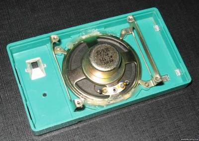
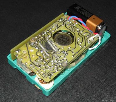
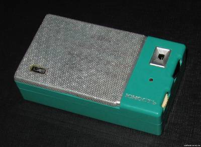
In the journal "Radio" No. 9 for 1965 The radio designer "Youth" was described. It was one of the first Soviet kits for assembling a pocket radio receiver - a "transistor", as they were then called. He is dear to me as a memory. This is what my parents gave me in 1973. We bought it in the central department store in Melitopol, where we were visiting my aunt. The case was a pleasant "sea wave" color - as in the photograph on the website "Domestic Radio Engineering of the 20th Century".
I assembled it then, but my teacher helped me to set it up in English, Valery Nikolaevich, who himself was an avid radio amateur. Later, in the case from this radio designer, I assembled the receiver according to a scheme that was very popular at the time. And then he got lost somewhere in space-time...
With the help of colleagues from site "Domestic radio engineering of the twentieth century" I managed to find a case from this designer. Almost the same color, but completely empty. Later, we managed to find two "half-corpses" of a later modification of this constructor - "Youth KP-101". Its case, of course, is no longer so beautiful, but the dimensions of the boards and the installation accessories are the same for both sets. It was then that the idea arose to assemble a receiver in the building of the first "Youth". Very few stations are now broadcasting in the MW or LW bands, but, for example, in the "upper" VHF band in St. Petersburg, there are now about 30 of them. So the choice was obvious - VHF receiver for receiving stations in the range of 87.5 ... 108.0 MHz.
Receiver circuit.
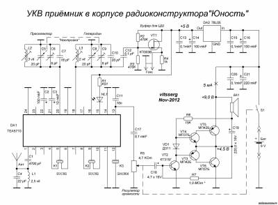
The next stage is the development of a schematic diagram. A fully transistorized version was not even considered, since it is very difficult to set up. I also did not consider ICs with a low IF (KR174XA34, TDA7021 and others) - I already had experience in designing receivers on them and I did not like these devices. Therefore, one solution suggested itself - a superheterodyne on a "single-chip" receiver IC. There are a great many microcircuits of this class, the parameters for all of them are approximately the same. Therefore, when choosing, I was guided by its availability, price, “strapping” and ease of setup. In all these respects, I liked TEA5710. Moreover, there was already a positive experience in manufacturing receivers on it (Fig. 2, 3).
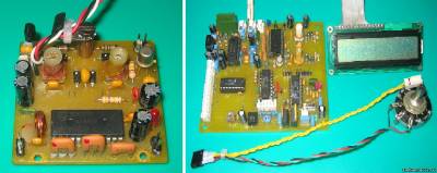
Fig.2 Fig.3
In the binding of this IC, two band-pass filters and a detector on a piezoceramic discriminator are used. This allows you to get a fully tuned node "HF - detector" ... without any configuration at all. And this makes it very, very easy to set up the receiver as a whole. In fact, it remains only to stack the range and adjust the gain uniformity throughout the range. In principle, this can be done even without instruments, “by ear”.
The TEA5710 switching circuit is standard, from the datasheet. Some moments "peeped" in the book B.Yu. Semyonov "Modern tuner with your own hands". In particular, a buffer stage node for connecting a digital scale. He helped me a lot when I did the first setup of the finished receiver - I specified the parameters of the coils and capacitors of the local oscillator and the preselector. In principle, this node can not be assembled - just leave empty spaces on the board. If you make coils according to the recommendations given, and the KPI overlap does not differ much from that indicated in the diagram, then, with a high degree of probability, you will “fall” into the desired range.
The second half of the receiver is ULF. At first I wanted to assemble it on some low-power ULF IC. I rummaged through a lot of literature and reference books, but, to my surprise, I didn’t find anything suitable ... Either stereo (but you need mono), then the power is high, then the supply voltage is not suitable, then the current consumption is large, then the case is “planar” ( but I wanted DIP), then you can’t find it in stores in principle ... In general, in the end I decided to make ULF on discrete elements. At first there was an idea to make a transformer, as in the original Youth. But he quickly abandoned it, because finding transformers in our time is not easy. Then there was an idea to make on modern transistors. And then I accidentally stumbled upon a circuit on old MP-scales with very good parameters. I assembled a layout of this amplifier, drove it in different modes, “listened” with an oscilloscope and how it plays music - I liked it. And the issue with ULF was resolved in favor of this amplifier.
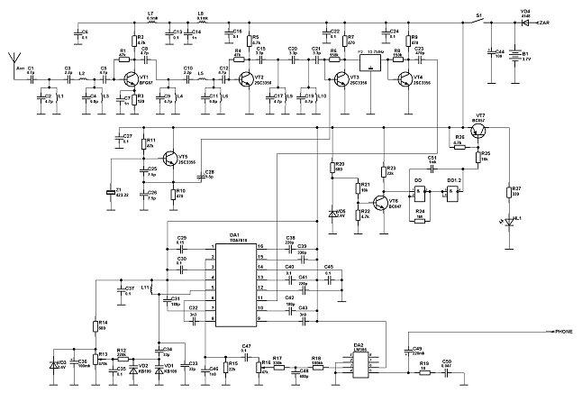
As a result, such a receiver circuit was “born” (Fig. 4) .
Actually, it makes no sense to describe her work. The receiving part is comprehensively described in the datasheet on the TEA5710 IC (and in the mentioned book by Semyonov). ULF is described in detail in the mentioned article by Polyakov (all this is in the archive - link above). I will note only a few points.
The TEA5710 IC is powered from +5 V, for which a voltage regulator is assembled on the board on the IC 78L05 (elements C13 C14 DA2 C15 C16). The buffer stage for the digital scale is also powered from it (elements C12 R2 R3 VT1 R4). As already noted, if the scale is not planned to be connected, then these elements can simply not be installed on the board. No jumpers or alterations need to be done.
The receiver IC itself is "hard" switched to the "FM" mode (the 14th leg is connected to the "ground"). The TEA5710 also has an AM path, but in this case it is not used. LED HL1 is an indicator of fine tuning. It is better to use a red LED with a diameter of 3 mm. I managed to “squeeze” it between the tuning and volume knobs.
Printed circuit board.
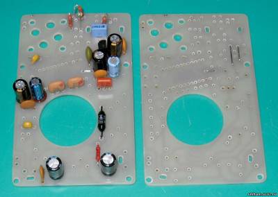
Based on this scheme, a printed circuit board was developed, the dimensions are exactly the same as the "original" Yunosti board - 86 x 53 mm (Fig. 5).
It is quite difficult to develop a board for which the dimensions, holes for mounting in the case and for the speaker, as well as the location of the controls (volume control and KPI settings) have already been determined ... For a very long time I "suffered" with the placement of the IC. Sometimes, there was a great desire to “break” it ... J Well, it didn’t “fit in” in any way ... And the requirements for wiring are rather contradictory. On the one hand, you need to spread the preselector and local oscillator coils as much as possible, on the other hand, place them closer to the KPI and the IC, which doesn’t fit anyway ... And also the wiring of the “common” wire ... But everything turned out more or less fine when I realized to turn the case The IC is literally a few degrees clockwise. There were few jumpers, only 3 pieces, but they are there ...
The drawing of the board is made in the format of the Sprint Layout - 5 program. in the File directory.
In addition, in the same there is a lot of reference and other material designed to help in the work on creating a receiver.
The board is made of one-sided foil fiberglass 1.5 mm thick using the LUT method. All holes must be drilled before cutting boards "in size", since the mounting holes are located on the very edge of the board and with inaccurate drilling, you can simply break it. Next, the board must be cleaned with a fine sandpaper (1000 ... 2000), tinned and washed with alcohol (acetone).
KPI - from the Chinese receiver. It has 2 sections for AM (which are not used), 2 sections for VHF with a maximum capacitance of approximately 20 pF and 4 trims with a maximum capacitance of 8 pF. The KPI leads are the main fastening element, since the KPI itself is attached to the board "in reverse".
Piezoceramic filters (Fig. 7) can use any bandpass ( non-rejection- pay attention to this!) At 10.7 MHz. Also present in many Chinese receivers. Sometimes found in regular and online stores. Like a piezoceramic discriminator. Here it, perhaps, may turn out to be the most scarce part in this receiver. I also note that this NOT QUARTZ!
Coils. There are only three of them (Fig. 8).
L1 - frameless, contains 2.5 turns of PEL or PEV wire with a diameter of 0.4 ... 0.6 mm. The coil is wound on a mandrel with a diameter of 6 mm (for example, a drill shank). Does not require settings. After installation on the board, you can fix it with a few drops of paraffin (drop from a burning candle).
L2 - contains 3 turns of PEL or PEV wire with a diameter of 0.4 ... 0.6 mm
L3 - contains 2 turns of PEL or PEV wire with a diameter of 0.4 ... 0.6 mm
L2 and L3 are wound on polystyrene frames with a diameter of 5 mm with a tuning core made of copper or brass, M3 or M4. If you can find frames with a groove, that's even better. After winding, before installing on the board, it is desirable to fix the turns with paraffin.
Transistors in the ULF (Fig. 9) can use any of the series P10 - P16, MP37 - MP42 of the corresponding conductivity. It is necessary to match in pairs with close odds. amplification VT3-VT4 and VT5-VT6. For their installation, it is desirable to use plastic stands.
Resistors - any output power of 0.125 ... 0.25 W.
Variable resistor - domestic or imported ("wheel") with a switch, resistance 4.7 - 47 kOhm.
Capacitors (non-polar) - small-sized ceramic. As C17, it is desirable to use film. Electrolytes - any high-quality (usually imported).

Loudspeaker - domestic (0.1 GD-6, 0.2GD-1, etc.) or imported (I used an 8-ohm speaker from an old PC system unit) with a resistance of 6 - 8 ohms and suitable dimensions.
Antenna - telescopic, 400 - 600 mm - whatever you find, suitable in size and design.
Assembly and setup.
It is desirable to assemble and configure in approximately the following sequence.
First, solder three jumpers (Fig. 13). Then we install all the fixed resistors and capacitors, IF filters, wind and solder all the circuits. In a word, all passive components. We install a stabilizer on the IC board and check the output voltage - it should be. + 5 V. Before switching on for the first time, it is advisable to wash the board from the soldering side with alcohol. After that, we install ULF transistors (VT2 ... VT6), matched in pairs. We check everything again. Instead of R7, we temporarily turn on a 1.0 MΩ constant resistor plus a 470 KΩ trimmer in series with it.
We connect the speaker, we short-circuit the "minus" C18 to the ground, we connect the "Krona". Next, we connect a milliammeter at the limit of "20 mA" instead of a power switch and check the current consumption of the amplifier. He d.b. about 5 mA. Next, instead of the power switch, we temporarily put a jumper and control the voltage at the "minus" C19. It should be half the supply voltage. We achieve this by selecting R7 (changing the resistance of the tuning resistor). Then we measure the total resistance and solder a constant resistor. I got about 1.3 MΩ.
After that, you can “listen” to it with a generator and an oscilloscope, or simply send a signal from any source, for example, the same PC. Naturally, minus C18 before this must be torn off the ground. The amplifier should sound loud and clear, without overtones and audible distortion (and it “screams” very strongly!).
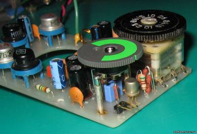
Next, install the KPI and the variable resistor. This is perhaps the most difficult stage in the installation of the receiver. KPIs come in different heights. Therefore, it is better to do so. We determine where he has the conclusions of the FM sections. The easiest way is to use a capacitance meter. If it is not there, then, with a high degree of probability, they are on the side where the conclusion was made in the upper part of the KPI (circled in red in the photo) (Fig. 14).

The tuning dial from "Youth" has exactly the same seat as on the imported KPI, but in the "native" KPI it is fixed with an M3 countersunk screw, and in the imported one - with an M2.5 screw. I put a washer made of soft material under the screw (for example, it can be made of cambric) and the limb turned out to be well fixed (circled in red in Fig. 6).
Next, we install the KPI on the board without soldering, and install the board in the case and be sure to fix it with fixing screws. We set the desired position of the KPI and determine how much it needs to be raised above the board. In my case, it turned out to be 3 mm. Next, I cut out 4 small corners from 3 mm thick plastic and glued them to the KPE with dichloroethane (Fig. 15).
We set the trimmers to the middle position, again install the KPI on the board and fix it in the case. If everything has risen as it should, we solder the KPI right in place. You can additionally "grab" it to the board with a few drops of hot glue from a gun.
Similar "torments" are coming with a variable resistor. The conclusions must first be lengthened with wires. Also, its installation must be carried out "in place" (Fig. 16).
Only after that you can install the TEA 5710 IC. You can simply solder it into the board, or you can install it on the socket. I did not come across 24-foot panels with a pitch of 1.778 mm and a raster of 10 mm, but you can easily find a 30-foot one. Removing the "extra" 6 contacts, we get what we need.
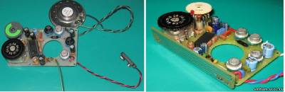
Fig.17 Fig.18
Once again, we very carefully wash the board from the flux residues and “in the light” we look through all the solderings in the IC area. We solder the power block, loudspeaker and antenna - a piece of wire half a meter long - a meter (Fig. 17). After making sure that there are no random jumpers between the tracks, turn on the receiver. Immediately we should hear a characteristic "hiss". We need to try to tune in to any station and decide which part of the range we "hit". This is where a digital scale can help very well, which can be connected to a buffer stage on a field-effect transistor. In the absence of a digital scale or frequency meter, you can try to tune the receiver using an industrial receiver.
We turn the KPI adjustment dial counterclockwise until it stops and by adjusting local oscillator coils L3 tune in to the most lower"band station (87.5 MHz, in St. Petersburg this is" Road Radio "). Then we turn the KPI clockwise until it stops and using trimmer C9 tune in to the station top"station (in St. Petersburg it is "Russian Radio", 107.8 MHz). Such adjustments must be repeated several times, since they are interdependent.
The preselector is adjusted in the same way: “down” - with the L2 coil, “up” - with the C6 trimmer according to the maximum undistorted volume of the stations. For more precise tuning, the length of the antenna can be reduced.
Coil L1 does not need to be adjusted.
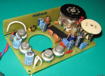
A little about the antenna. At first I decided to make a "printed" one and install it in the same place where the magnetic one stood in the "original" Youth. For fastening, I used 2 double wire corners. In antennas, to put it mildly, I am not strong, so I just drew 2 options in the form of "snakes". The total length of the conductor of one snake turned out to be 440 mm, the other - 390 mm. But it turned out that these antennas work very poorly ... I tried both, selected the parameters of the circuits, tried to make some kind of "dipole" out of them - all in vain. Perhaps there are printed antennas for this range, perhaps you need to make the correct matching - I don’t know, I repeat once again, I’m not strong in antennas. So far, I see only one solution - a telescopic antenna. And so you don’t want to “perforate” the body ... (Fig. 18, 19).
Although, one hole has already been made - for the fine-tuning LED (between the tuning dial and the volume control - everything is "on the verge of a foul" in terms of placement). It must also be installed in place, after marking the hole in the top cover of the receiver.
Next, we install the board into the case using standard Yunost brackets. (Fig.20). Under the fixing screws, which are located closer to the KPI and the volume control, it is imperative to lay washers made of insulating material.
We close the back cover and enjoy our work (Fig. 21). JMounting a telescopic antenna is as you wish and who will find which antenna ...
Vitsan Sergey Viktorovich
Saint Petersburg,
December 19, 2012.
Suggested to readers VHF FM receiver(see figure) is made on the basis of a direct conversion radio receiver with a PLL, developed at one time by a radio amateur from Krasnodar A. Zakharov (see "", 1985, No. 12, pp. 28-30).
the radio-frequency receiver stage is assembled on a VT1 transistor and is a frequency converter with a combined local oscillator, which simultaneously performs the functions of a synchronous detector.
The receiver antenna is a headphone wire. The signal of the broadcasting station received by it is fed to the input circuit L1C2, tuned to the average frequency of the received VHF band (70 MHz) and then to the base of the transistor VT1. As a local oscillator, this transistor is connected according to the OB circuit, and as a frequency converter, according to the OE circuit. The local oscillator is tuned in the frequency range of 32.9 ... 36.5 MHz, so that the frequency of its second harmonic lies within the boundaries of the VHF broadcasting range (65.8 ... 73 MHz). The L2C5 circuit is tuned to a frequency half that of the L1C2 input circuit, and since the conversion occurs at the second harmonic of the local oscillator, the difference frequency is in the audio frequency range. Amplification of the difference frequency signal is provided by the same transistor VT1, which, like a synchronous detector, is connected according to the OB circuit.
Amplifier 3H receiver two-stage. The pre-amplification stage is made on a transistor VT2, and the power amplification stage is made on a transistor VT3. Listen to the received transmissions on the head telephone BF1 (TM-4). The output power of the 3H amplifier at a load with a resistance of 8 ohms when powered by one A332 element (1.5 V) is 3 mW, which is quite enough to work on a head phone. The current consumed by the receiver from the power supply does not exceed 10 mA.
The receiver can be assembled in any small-sized case. Hanging installation. Resistors - MLT-0.125, oxide capacitors - K50-6, trimmers - any with an air dielectric, the rest are KM, KLS. Coils L1 and L2 are frameless. Winding inner diameter - 5, step - 2 mm. Coil L1 contains 6 (with a tap from the middle), and L2 - 20 turns of wire PEV-2 0.56. Coils L3, L4 each contain 200 turns of PEL wire 0.06. They are wound on a ferrite (M400NN) rod with a diameter of 2 and a length of 10 mm in two wires. Transistor VT1 can be replaced by KT3102B, while the sensitivity of the receiver will increase.
Setting up the receiver begins with a 3-hour amplifier. The operation mode of transistors VT2, VT3 is set by selecting resistor R5 until the collector quiescent current of transistor VT3 is equal to 6 ... 9 mA. The local oscillator mode is regulated by the selection of resistor R1, the level of the second harmonic of the local oscillator - capacitor C6. The boundaries of the received frequency range are set by changing the inductance of the coil L2. The input circuit is tuned by capacitor C2, focusing on the maximum holding band of the signals of the received radio stations. The receiver is tuned in range by capacitor C7.
Setting recommendations:C7 is not particularly twisted. Instead, catch the station by changing the length (inductance) of the coil L2. Capacitor C2 serves for fine tuning. When you have caught the station, then turn C2 until the sound becomes clear. Yes, and you may have to pick up the power of the receiver. Since 1.5V indicated on the diagram, in my case it was not enough. Powered by about 7 volts. You can also add an antenna to the bottom one according to the diagram, the output of the capacitor C1.? But this is if it is completely deaf.