DC welding machine. DC welding inverter
Autonomous voltage inverter is designed to convert direct voltage into alternating voltage. There are also current inverters, they convert direct current into alternating current. However, the most widely used voltage inverters. They are used to convert direct voltage, such as rectifiers, batteries or solar panels, into alternating voltage, most often with a frequency of 50 Hz or any other frequency with the possibility of its regulation.
Single-phase autonomous voltage inverter. Operating principle
The alternating voltage at the load is formed by short-term alternating connections of the DC voltage power source to the opposite load terminals, that is, at one point in time, the power source with its own terminals 1-2 connected to load terminals 3-4 , and the next - to the terminals 4-3 . (rice. one ) As a result, the current through the load first flows in one direction, and then in the other. With an increase in the frequency of such switching, the frequency increases. alternating current on load.
Rice. 1 - Autonomous voltage inverter. Operating principle
Even easier to understand the formation process AC voltage from constant it is possible if you imagine that there is a resistor in one hand and a battery in the other. In this case, the resistor is always in one fixed position, and the battery is connected either with a pole or a minus to the same terminal of the resistor. Thus, the current through the resistor will flow either in one direction or in the opposite direction. In fact, the role of switches is performed by semiconductor switches.
A schematic diagram of an autonomous voltage inverter is shown in rice. 2.
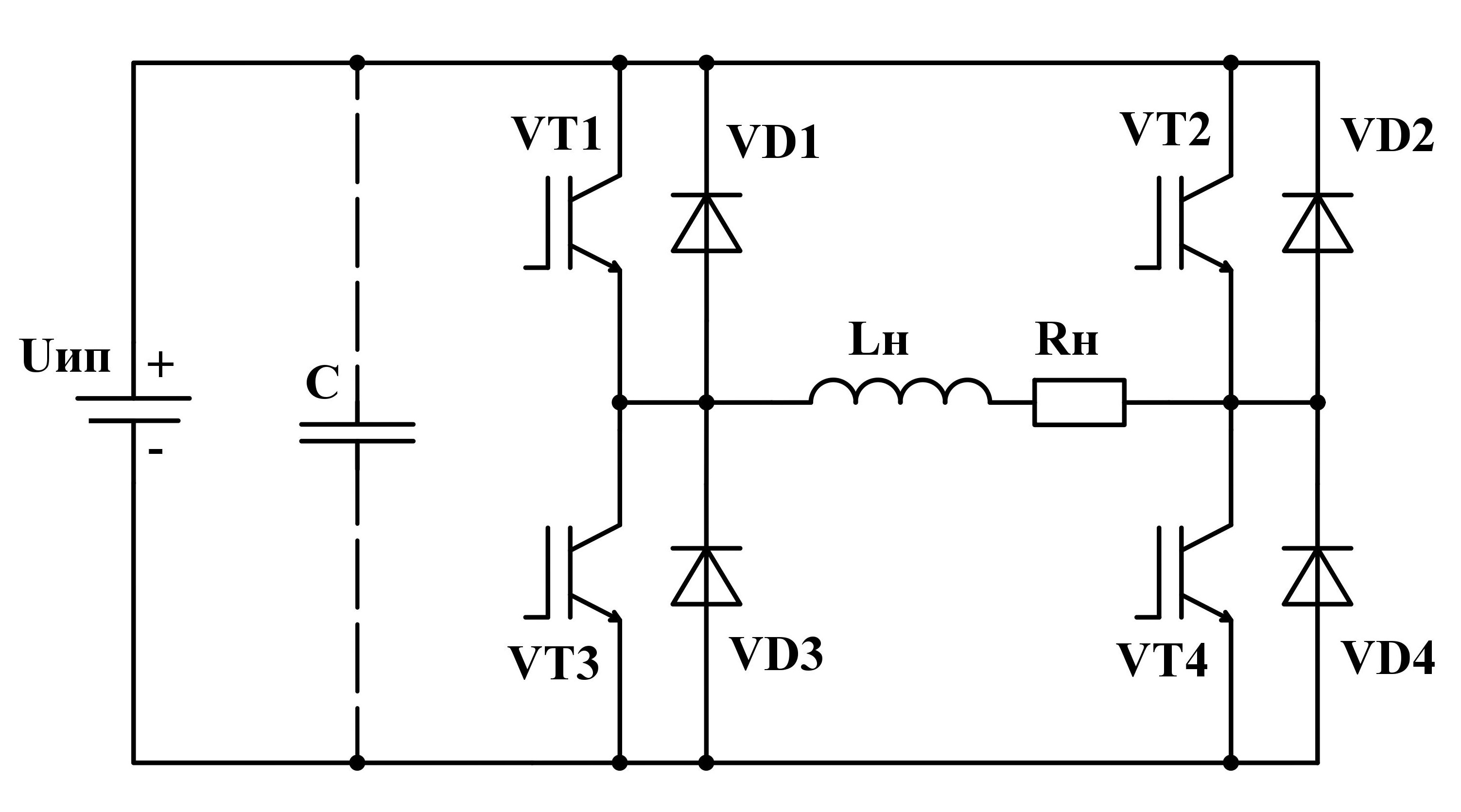
Rice. 2 - Autonomous voltage inverter. circuit diagram
Consider the operation of the inverter on the example of an active-inductive load, as the most common
At some point in time t 1 (rice. 3 ) one pair of diagonally opposite transistors VT 1 , VT 4 open and the other VT 2 , VT 3 is closed. The current flowing through the voltage inverter and the load increases exponentially with a time constant τ= L H / R H along the path "+" U IP – VT 1 – L H R H – VT 4 – «-» U IP . The next moment t 2 (rice. four ) transistors VT 1 , VT 4 closed and VT 2 , VT 3 are open.

Rice. 3 - The path of current flow through the elements of the inverter on the time interval t1-t2

Rice. 4 - The path of current flow through the elements of the inverter on the time interval t 2- t 3
However, due to the presence of inductance L H the current cannot instantly change its direction. Therefore, at the moment t 2 closing transistors VT 1 , VT 4 and discoveries VT 2 , VT 3 current continues to flow through the inverter in the same direction as long as the energy stored in the inductor magnetic field W L n = L H I 2 /2 does not drop to zero (time interval t 2 — t 3 ) (cm. rice. four ). Because transistors VT 1 , VT 4 already closed, then the current will flow through the following circuit: L H R H – VD 2 – U IP – VD 3 . During this time interval, energy from the load is given to the power source U IP .
If a rectifier is used as the power source, then it must be shunt capacitor C. This will allow current to flow in the opposite direction.
In the moment t 3 (rice. 5 ), the current will drop to zero, after which its direction will change. In the span of time t 3 < t < t 4 the current will increase, flowing along the path: "+" U IP – VT 2 – L H R H – VT 3 – «-» U IP . In coins of time t 4 transistors VT 2 , VT 3 will close again, VT 1 , VT 4 will open. Current over time t 4 < t < t 5 will continue to flow in the same direction until it drops to zero. Current path: L H R H – VD 1 – U IP – VD 4 .

Rice. 5 - The path of current passage through the elements of the inverter on the time interval t 3- t 4
At the next moment in time t 5 (rice. 6 ) the current will become equal to zero, and then, changing its direction, will begin to increase in the time interval t 5 < t < t 6 . In the moment t 6 the transistors will switch again and the processes will repeat.
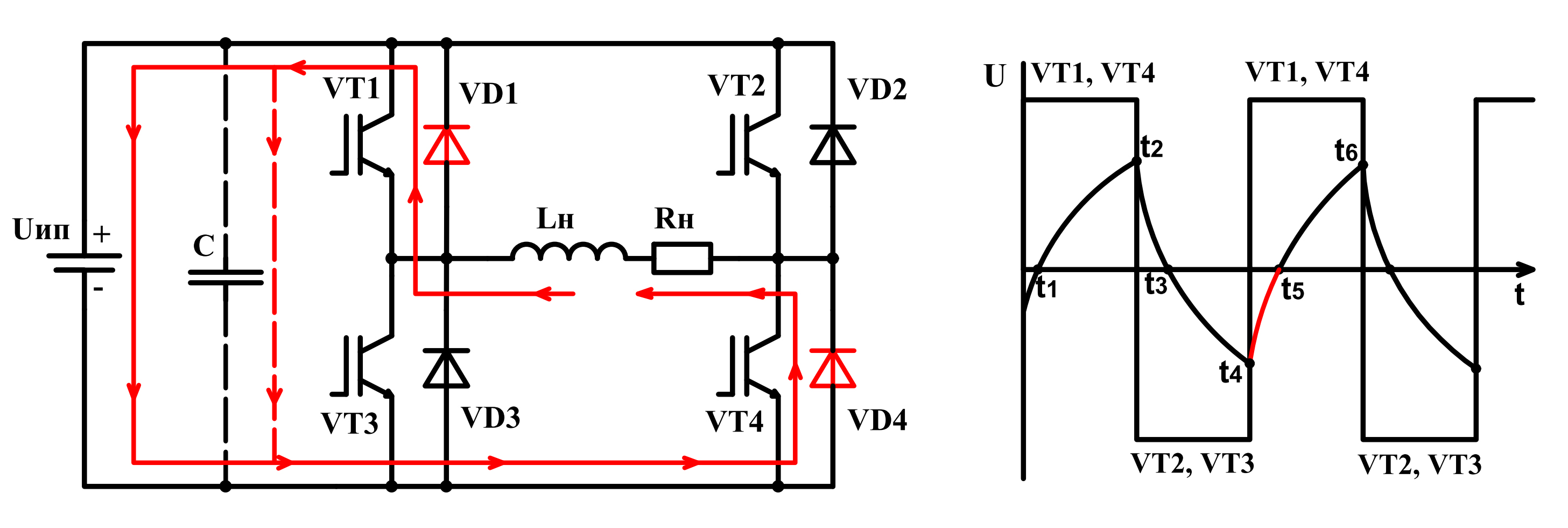
Rice. 6 - The path of current passage through the elements of the inverter on the time interval t 5- t 6
Current flows through the "+" circuit U IP – VT 2 –R H L H – VT 3 – «-» U IP . So transistors VT 1 …VT 4 alternately connect the power supply U IP to load terminals: positive first U IP connected to 3 -th terminal, and minus to 4 -th terminal, then vice versa.
The transistor control algorithm discussed above allows you to keep the inverter output voltage and, accordingly, the load current constant, but in most cases it is necessary to change the voltage in order to obtain the required current in the load.
Ways to regulate the voltage of an autonomous inverter
There are two ways to regulate the output voltage of the inverter:
1) the first way is to change the magnitude of the voltage of the power source U IP;
2) the second method is implemented using the so-called internal means of the inverter, namely by changing the shape of the output voltage.
The first method is quite simple and requires only a regulated power supply. The essence of the second method is as follows. To change the voltage at the output of the inverter, it is necessary to shift the control pulses applied to the bases of the transistors VT 2 and VT 4 , relative to the control pulses on VT 1 and VT 3 on control angle α (rice. 7 ).

Rice. 7 - Algorithms for controlling transistors of a single-phase voltage inverter
Consider the operation of the inverter on when adjusting the output voltage
On the time interval t 1 < t < t 2 (rice. eight ).open transistors VT 1 and VT 4 the voltage on the load is equal to the power supply u n = U IP . The next moment t2 closes VT 1 and opens VT 3. For a time t 2 < t < t 3 (rice. 9 ) current flows through the circuit R H L H – VT 4- VD 3 and the load is shorted, as a result of which the voltage across it is zero u n =0 . In the moment t3 trigger signal is applied to the base of the transistor VT 2 and removed from the base VT 4 .
As a result, the power supply voltage is applied to the load u n = — U IP . The presence of inductance in the circuit leads to the fact that in the time interval t 3 < t < t 4 (rice. ten ) the current through the inverter continues to flow in the same direction: L H R H – VD 2 – U IP – VD 3 , and after it drops to zero, it will change its direction and flow along the chain: U IP – VT 2 – R H L H – VT 3 (rice. eleven ).

Rice. 8 - Path of the current in the time interval t 1- t 2
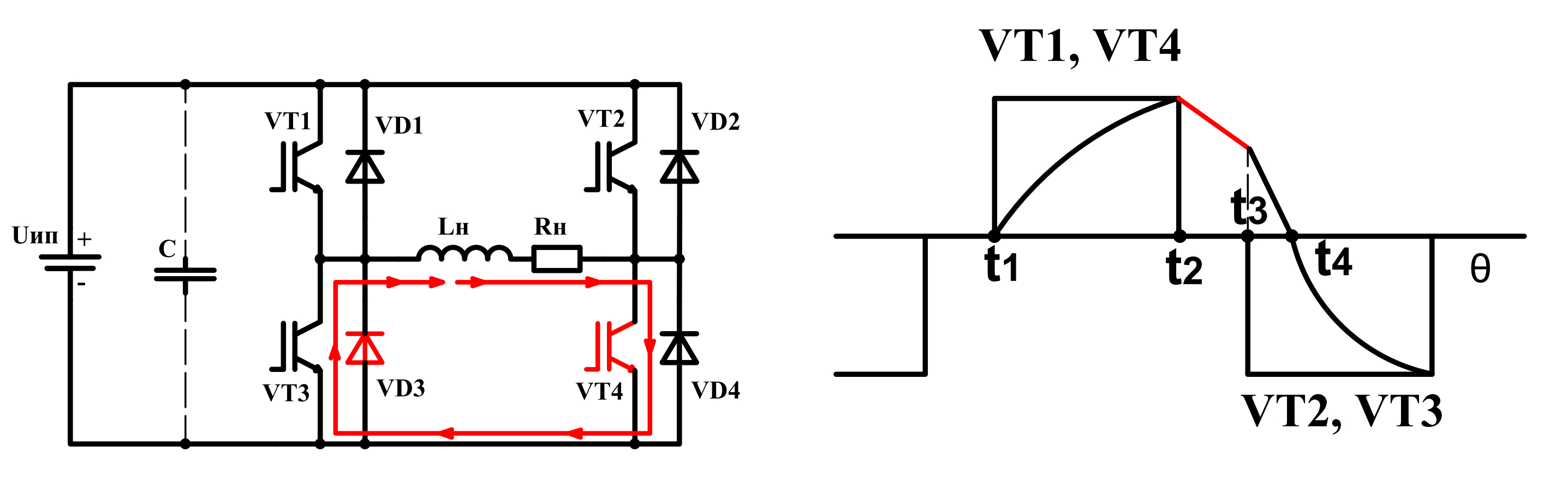
Rice. 9 - Path of the passage of current in the time interval t 2- t 3
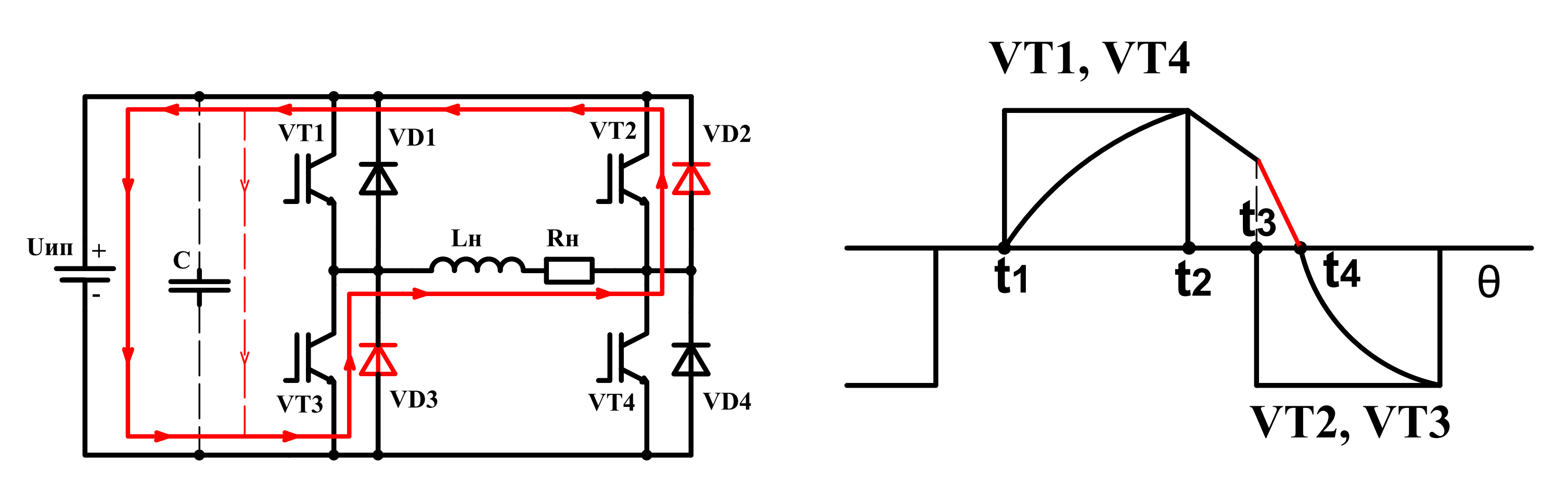
Rice. 10 - Path of the current in the time interval t 3- t 4

Rice. 11 - Path of the current in the time interval t > t 4
As a result of applying such a transistor control algorithm, a pause occurs in the voltage curve, which entails a decrease in the effective voltage value. Therefore, to regulate the voltage at the output of the inverter, it is necessary to change the control angle α.
This article discusses the principle of operation of a single-phase two-level voltage inverter, however, there are also multi-phase and multi-level inverters, but the basis of their operation is the principle of operation of the considered inverter.
To convert direct current to alternating current, special electronic power devices called inverters are used. Most often, an inverter converts a DC voltage of one magnitude into an AC voltage of another magnitude.
In this way, an inverter is a generator of periodically changing voltage, while the voltage shape can be sinusoidal, close to sinusoidal or pulsed. Inverters are used both as independent devices and as part of uninterruptible power supply systems (UPS).
In the sources uninterruptible power supply(UPS), inverters allow, for example, to receive continuous power supply to computer systems, and if the voltage suddenly disappears in the network, the inverter will instantly start feeding the computer with energy received from the backup battery. At least the user will have time to shut down correctly and turn off the computer.
Larger uninterruptible power supplies use larger inverters with large batteries that can autonomously power consumers for hours, regardless of the network, and when the network returns to normal, the UPS will automatically switch consumers directly to the network, and the batteries will begin to charge.

Technical side
AT modern technologies In order to convert electricity, an inverter can only act as an intermediate link, where its function is to convert voltage by transforming it at a high frequency (tens and hundreds of kilohertz). Fortunately, today it is easy to solve such a problem, because for the development and design of inverters, both semiconductor switches capable of withstanding currents of hundreds of amperes, and magnetic circuits of the required parameters, and electronic microcontrollers specially designed for inverters (including resonant ones) are available.
Requirements for inverters, as well as for other power devices, include: high efficiency, reliability, as small overall dimensions and weight as possible. It is also necessary that the inverter withstand the permissible level of higher harmonics in the input voltage, and not create unacceptably strong impulse noise for consumers.
In systems with "green" sources of electricity (solar panels, windmills) to supply electricity directly to the general network, Grid-tie inverters are used - inverters that can operate synchronously with the industrial network.

During the operation of the voltage inverter, a constant voltage source is periodically connected to the load circuit with polarity alternation, while the frequency of connections and their duration is formed by a control signal that comes from the controller.
The controller in the inverter usually performs several functions: adjusting the output voltage, synchronizing the operation of semiconductor switches, and protecting the circuit from overload. In principle, inverters are divided into: autonomous inverters (current inverters and voltage inverters) and dependent inverters (driven by the network, Grid-tie, etc.)
Inverter circuitry
The semiconductor switches of the inverter are controlled by the controller and have reverse shunt diodes. The voltage at the output of the inverter, depending on the current load power, is regulated by an automatic change in the pulse width in the high-frequency converter unit, in the simplest case it is .
The half-waves of the low-frequency output voltage must be symmetrical so that the load circuits in no case receive a significant constant component (this is especially dangerous for transformers), for this the pulse width of the low-frequency unit (in the simplest case) is made constant.
In the control of the output keys of the inverter, an algorithm is used that provides a sequential change in the structures of the power circuit: direct, short-circuited, inverse.
One way or another, the value of the instantaneous load power at the output of the inverter has the nature of ripples with a double frequency, so the primary source must allow such an operation mode when pulsating currents flow through it, and withstand the corresponding level of interference (at the input of the inverter).
If the first inverters were exclusively mechanical, today there are many options for semiconductor-based inverter circuits, and there are only three typical circuits: a bridge without a transformer, a push-pull with a zero transformer output, a bridge with a transformer.
A bridge circuit without a transformer is found in uninterruptible power supplies with a capacity of 500 VA or more and in automotive inverters. The push-pull circuit with zero transformer output is used in low-power UPS (for computers) with a power of up to 500 VA, where the voltage on the backup battery is 12 or 24 volts. A bridge circuit with a transformer is used in powerful uninterruptible power supplies (for units and tens of kVA).
In voltage inverters with a rectangular output, a group of switches with freewheeling diodes is switched so as to obtain an alternating voltage at the load and provide a controlled circulation mode in the circuit.
The following are responsible for the proportionality of the output voltage: the relative duration of the control pulses or the phase shift between the control signals of groups of keys. In an uncontrolled mode of reactive energy circulation, the consumer affects the shape and magnitude of the voltage at the output of the inverter.
In step voltage inverters, the high-frequency pre-converter generates a unipolar step voltage waveform roughly approximating in shape a sinusoid with a period equal to half the period of the output voltage. The LF bridge circuit then converts the unipolar step curve into two halves of a bipolar curve roughly shaped like a sine wave.
In voltage inverters with a sinusoidal (or almost sinusoidal) output, the preliminary high-frequency converter generates a constant voltage close in magnitude to the amplitude of the future sinusoid at the output.
After that, the bridge circuit forms a low-frequency alternating voltage from a constant voltage, by means of multiple PWM, when each pair of transistors opens several times at each half-cycle of the formation of the output sinusoid for a time that varies according to the harmonic law. Then the low-pass filter extracts the sine from the resulting shape.
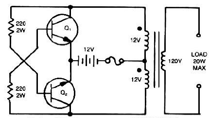
The simplest schemes for preliminary high-frequency conversion in inverters are self-oscillating. They are quite simple in terms of technical implementation and are quite effective at low powers (up to 10-20 W) to power loads that are not critical to the power supply process. The frequency of self-oscillators is not more than 10 kHz.
Positive feedback in such devices is obtained from the saturation of the transformer magnetic circuit. But for powerful inverters, such schemes are not acceptable, since the losses in the keys increase, and the efficiency turns out to be low as a result. Moreover, any short circuit at the output disrupts self-oscillations.
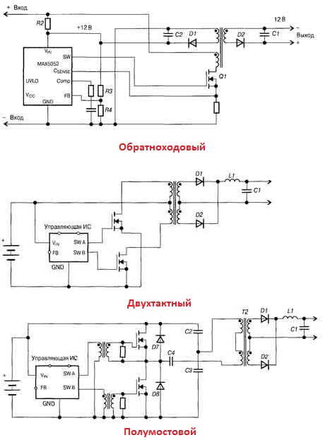
Better circuits of preliminary high-frequency converters are flyback (up to 150 W), push-pull (up to 500 W), half-bridge and bridge (more than 500 W) on PWM controllers, where the conversion frequency reaches hundreds of kilohertz.
Types of inverters, operating modes
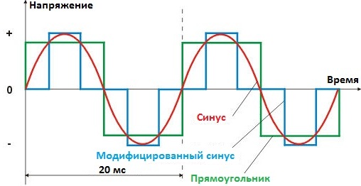
Single-phase voltage inverters are divided into two groups: with a pure sine output and with a modified sine wave. Majority modern appliances allow a simplified form of the network signal (modified sinusoid).
A pure sine wave is important for devices that have an electric motor or transformer at the input, or if it is a special device that works only with a pure sine wave at the input.
Three-phase inverters are commonly used to create three-phase current for electric motors, for example, for power. In this case, the motor windings are directly connected to the output of the inverter. In terms of power, the inverter is selected based on the peak value thereof for the consumer.
In general, there are three working modes of the inverter: starting, continuous and overload. In the starting mode (capacity charging, starting the refrigerator), the power can double the inverter rating for a fraction of a second, this is acceptable for most models. Continuous mode - corresponding to the rating of the inverter. Overload mode - when the consumer's power is 1.3 times higher than the nominal value - in this mode, the average inverter can work for about half an hour.
The word "inverter" in relation to electrical engineering means device that converts direct current to alternating current. In this case, the voltage amplitude can change up or down.
Inverters can be either separate devices (welding or voltage converter of the car's on-board network to 220 V AC), or a separate unit or part of the circuit (power supply for a computer, TV). We will now talk about devices used for power supply in emergency situations associated with the loss of mains voltage.
Where does tension go and when will it return?
No networks are 100% reliable. Suddenly, the lights in the apartment or house go out. This is due to damage to cable or overhead lines, electrical equipment of substations. Accidents within the city, if they are not related to natural disasters, are eliminated relatively quickly. For this, dispatch services and operational teams work. And it is possible to exclude the damaged section and replace it with another one because of their mutual redundancy.
In rural areas and summer cottages, everything is different. There is only one supply line, the brigade has to go far. After hurricanes or thunderstorms, the number of fallen trees on the wire lines increases the chances of staying in the dark for a long time. And if the power transformer is damaged, you will have to wait more than a day.
Time goes by, the food in the refrigerator spoils. Do not boil the kettle - it is electric. Nothing to cook dinner. The battery of the mobile phone is discharged - it is impossible to call the Ministry of Emergency Situations. In the dark, you can't find a cure for grandma. The heating appliances cool down, and with them the house itself.
To prevent this from happening need a personal, network-independent source of power supply. For this purpose, an inverter is used.
The principle of operation of the uninterruptible power supply
The simplest inverter computer uninterruptible power supply (UPS). Inside it is a battery that stores energy. It works in constant charge mode. For this purpose, the UPS includes Charger, which monitors the voltage level on the battery. Depending on it, it regulates the charge current or turns off the battery.

As soon as the supply voltage disappears, the control device disconnects the load from the network. At the same time, it is connected to the battery through an inverter, which is part of the UPS.
220V batteries exist, but they occupy a room the size of a room. Therefore, in all UPSs, batteries are made for low voltage. The inverter, converting it into a sinusoidal, simultaneously increases this value to the nominal mains voltage.
Such a power supply is good because always ready to work and switch instantly. But here are its main disadvantages, which do not allow the use of a UPS for uninterrupted power supply to a house or part of it:
Inverter for uninterrupted power supply at home
The inverter is a logical development of a computer uninterruptible power supply, devoid of its inherent disadvantages.

The increase in battery capacity is directly related to its overall dimensions. Placing it in the inverter housing becomes impractical. Therefore, it stands out as an independent device that solves three main tasks:
- battery charge and mains voltage control;
- switching supply sources;
- converting battery voltage to 220 V AC.
The main characteristic of the inverter is its power. But when choosing it, one nuance is taken into account. We have already said that the UPS cannot work with overload. The same goes for the inverter. If a refrigerator, electric motors of heating boiler pumps are planned as part of the load, then their starting currents are taken into account. At the moment of starting, electric motors consume current 3-5 times higher than the nominal one. If the total load current when the refrigerator is turned on exceeds the rated current of the inverter, the protection will turn it off.
Another characteristic of the inverter, which is worth focusing on, is the quality of the conversion of direct current to alternating current. The voltage in the network changes in time according to a sinusoidal law. No household semiconductor device will generate a sinusoidal voltage so that it exactly repeats the mains voltage. The output voltage does not change smoothly, but discretely, in steps. The more often this change occurs (higher sampling frequency), the more accurately the generated signal repeats the sinusoidal one.

But an increase in the sampling rate leads to a rise in the cost of the device. And the stepped voltage form is unacceptable for the operation of electric motors and some semiconductor devices. Such inverters, which produce the so-called modified sinusoid, are used only to power an active load: heating elements, incandescent lamps. For devices that are critical to the shape of the supply voltage, you will have to purchase a more expensive inverter.
The choice of batteries for the inverter
Batteries for inverter sold separately. But here there is a feature: batteries are acidic or alkaline. They have different charging principles, so each inverter is only suitable for operation with a certain type of battery. Otherwise, it will incorrectly determine the degree of charge of the batteries and charge them.

The use of car batteries as part of inverters is not justified. Although they are capable of delivering a powerful current pulse for a short time (in a car this is necessary for the starter to work), they do not tolerate deep discharges. And discharges are inevitable during long-term operation of the inverter. Therefore, the resource of such batteries in power supply systems is limited.
For work with inverters optimal application gel or fiberglass batteries. They are made according to special technology and are able to repeatedly transfer deep discharges without loss. And again: the inverter charger must support the charge mode of such batteries.

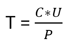
When choosing the battery capacity, proceed from desired battery life devices (T). It is easy to calculate it, knowing the capacity (C), the power of the planned load (P) and the battery voltage (U):
| Battery life calculation example | |||
| Battery voltage, V | Battery capacity, Ah | Working time, h | |
| 12 | 55 | 150 | 4 |
| 12 | 190 | 150 | 15 |
The numbers in the last column are not impressive. And the cost of inverters and batteries for them is not so small.
So does an inverter make sense?
Advantages and disadvantages of inverters
An alternative to inverters are diesel or gasoline generators. Therefore, we will identify their advantages by comparing them with generating electricity using internal combustion engines. Let's list disadvantages of generators, which can be eliminated with the help of inverters:
- the need to build a separate room with ventilation and heating in the winter;
- storage of fuel reserves (and for a diesel engine - replacement of summer fuel with winter fuel when cold weather sets in);
- noise at work, causing inconvenience not only to the owners, but also to neighbors;
- the need for periodic maintenance (checking the oil level, replacing candles, filters);
- manual start, the need to control parameters during operation.
The inverter does not require a separate room, it does not create noise during operation (the operation of cooling fans does not count). User intervention in the process is not required. When the battery is discharged (the voltage on the battery drops to the minimum possible level), the device will turn itself off and freeze, waiting for the mains voltage to recover. It will then charge the battery and wait until it can be useful again.
And automatic switching from mains power to battery power is captivating. But short inverter runtime. Even if you reduce the load to the minimum possible, sooner or later the battery will be discharged. The “end of the world” is delayed but inevitable.
Therefore, when deciding what to use for emergency power supply of a dwelling - a generator or an inverter, a complex of factors is considered.
Inverter or generator?
To start collect statistical data about how often and for how long the voltage disappears in a city or village. If these events happen very rarely, then it makes no sense to purchase a generator, build a separate room for it, where it will stand idle waiting in the wings.
Then determine the total power of electrical appliances, which are planned to be powered by an inverter in emergency operation. It makes no sense to include outdoor and basement lighting in this list, and if there are three TVs in the house, one is enough. In order to save money, they donate those electrical appliances without which you can survive a day or two. The rest, in the event of a power failure, will have to be disconnected from the network manually, or automation should be provided for this purpose.
But on the other hand, they take into account the heat supply system (heating boiler), if any. Moreover, taking into account all the starting currents of its electric motors, it is possible that it will have to start when the house is powered by an inverter.
And do not forget the main thing - the refrigerator with its starting current, if it is compressor. Also add to the list a microwave oven or an electric stove, an electric kettle.
According to the total load power choose inverter model, considering additionally what quality the sinusoidal voltage it will produce.
Then batteries are selected taking into account the desired operating time of the inverter for the previously calculated load. And here a reasonable approach is needed. If finances are not enough, then you will have to think in advance what you can donate. At the forefront are those loads that require constant work: a refrigerator, a boiler, heating appliances. Computers and TV will have to be turned off at some point in order for the inverter battery to last longer.
It remains to add up the prices, getting the total amount. And do the same calculation for generator set. Here, too, you can save money: with infrequent outages from the network, it is not at all necessary to build a room for it. You can store it in the barn, and if necessary, take it outside and connect it to the network using flexible cable and detachable connection. Be sure to add to the list the spare parts needed to service the installation during the lifetime of the alternative inverter. This is the only way to calculate the economic effect, and not the initial costs of purchasing equipment. The inverter will not require additional investments throughout its entire service life, but the internal combustion engine always needs maintenance.
Now we compare the resulting sums and make a decision. And remember: You always have to pay for comfort. Whether you are ready for it or not is up to you.
Thyristor inverters - these are devices that operate on an autonomous load and are designed to convert DC voltage into AC voltage of a given or adjustable frequency. by inverting call the process of converting direct current energy into alternating current energy (Fig. 1).
Fig.1 Diagram of direct and alternating current.
Application:
1. In power supply systems for AC consumers, when the only source of power is a DC voltage source (for example: a battery or solar battery).
2. In systems of guaranteed power supply in the event of a power failure (for example: for personal needs of power plants, computers).
3. For frequency regulation of the speed of asynchronous motors.
4. To supply AC consumers from DC power lines.
5. In converters for converting a constant voltage of one value into a constant voltage of another value.
Switching elements in inverters are thyristors or power transistors.
Inverters are divided into:
1. Autonomous inverters and frequency converters.
2. Grid driven inverters.
Autonomous inverters and frequency converters.
Autonomous inverters - these are devices that convert direct current into alternating current with a constant or adjustable frequency and operate on an autonomous load. Unlike grid-driven inverters, the stand-alone AC-side inverter has no other power source of the same frequency other than the inverter itself.
Frequency converters - These are devices that convert alternating current of one frequency into alternating current of another frequency.
To autonomous inverters and frequency converters, working in a particular installation, the following requirements apply:
1) ensuring maximum efficiency;
2) the minimum installed capacity of individual nodes and elements;
3) the possibility of wide regulation of the output voltage;
4) ensuring the stability of the output voltage when changing the magnitude and nature of the load, as well as the input voltage;
5) providing a sinusoidal or near-sinusoidal output voltage curve;
6) the possibility of regulation within certain limits of the output frequency, which is primarily necessary in the installations of the valve electric drive;
7) the absence of inversion failures during overloads;
8) the ability to work in idle mode;
9) ensuring maximum reliability and stability. Naturally, the requirements for autonomous inverter circuits depend on the specific purpose of the inverter. That's why best option inverter circuits must be selected taking into account the mode of operation of the loads fed from it.
Stand-alone inverters can be classified according to the following main features:
1) according to the conversion scheme;
2) according to the method of switching (locking);
3) according to the method of management;
4) by the nature of the flow of electromagnetic processes.
There are the following main conversion schemes:
1) single-valve (Fig. 2.1, a);
2) single-phase with zero output (Fig. 2.1, b);
3) single-phase with a zero output of the power source (Fig. 2.1, in);
4) single-phase bridge (Fig. 2.1, d);
5) three-phase bridge (Fig. 2.1, e);
6) three-phase with zero output (Fig. 2.1, e).
All other schemes are derivatives of the listed groups. Bridge circuits are the most widely used in converter technology. According to the switching method, autonomous inverters can be divided into several groups.

Rice. 2.1. Conversion schemes
Inverters with individual commutation. The switching device of the inverter serves to lock one thyristor (valve arm) of the inverter. This type of inverter includes inverters based on fully controlled gates - two-operation thyristors and power transistors.
Phase-switched inverters. The switching device of the inverter is used for alternate locking of the thyristors of two valve arms belonging to one phase of the inverter.
Group switching inverters. In such inverters, a separate switching device is used to lock all valve arms of one group (anode or cathode).
Common switching inverters. The switching device is common to all valve arms of the inverter. The switching device of the inverter contains one switching capacitor.
Valve-to-gate switching inverters. In such inverters, the locking of each working thyristor occurs when the next thyristor in the order of operation of another phase, but of the same group, is unlocked.
Phase-to-phase switching inverters. The switching device of the inverter is used for alternate locking of two thyristors of different phases.
According to the control method, inverters are divided into inverters with self-excitation and with external (independent) excitation.
In inverters with self-excitation, the control pulses applied to the thyristors are formed from the output voltage of the inverter. The output voltage frequency is determined by the load parameters.
In inverters with independent excitation, control pulses are generated by an external generator, which sets the frequency of the output voltage. Due to the fact that the frequency of the output voltage does not depend on the load parameters, this type of inverter is the most widely used in converter technology.
Depending on the characteristics of the flow of electromagnetic processes, autonomous inverters can be divided into three main types: current inverters(Fig. 2.2, a); voltage inverters(Fig. 2.2, c); resonant inverters(Fig. 2.2, e).
For current inverters, it is characteristic that they form a current in the load ( i out) and the shape and phase of the voltage depend on the parameters of the load.
The DC source operates in the mode of a current generator, for which input circuit the reactor turns on L d with high inductance. In addition, the reactor L d performs the functions of a filter of higher harmonic voltages, since the difference between the constant voltage of the power source and the pulsating voltage at the input of the inverter is applied to it at any time; prevents the discharge of the capacitor to the power source during the switching of current in thyristors and provides an aperiodic mode of operation of the inverter, characterized by small ripples of the input current. It should be noted that when the inverter is powered from sources with characteristics close to the current source, the inductor L d may be missing.
The current inverter must provide an operating mode in which a negative voltage is maintained between the anode and cathode of the closed thyristor for some time, which is necessary to restore the blocking properties of the thyristor. This time t off is called the locking time (Fig. 2.2, b).
With the active-inductive nature of the consumer, the reactive power balance is provided by switching and compensating capacitors. Capacitors in relation to the load can be connected in parallel, in series, in series-parallel.
Current inverters are characterized by energy exchange between switching and compensating capacitors included in AC circuits, load circuit reactances and a choke L d in the input circuit.
In the idle mode, the current inverter is inoperable due to the increase in the amplitude of the reverse and forward voltages on the thyristors. When overloaded, its work is difficult due to insufficient time to restore the locking properties of the thyristors. Current inverters have an output voltage close to sinusoidal, relatively small input current ripples, the ability to reverse the direction of the power flow without changing the direction of the current (when switching to the rectifier mode). The external characteristic of the current inverter is soft.

Rice. 2.2. Single-phase current inverter bridge circuit ( a) and voltage inverter ( in); time diagrams of current and voltage at the output of the current inverter ( b), voltage inverter ( G) and resonant inverter ( d) with active-inductive load
Voltage inverters form voltage in the load, and the shape and phase of the current depend on the nature of the load. The voltage inverter power supply operates in the voltage generator mode. If the inverter is powered by a rectifier, then a capacitor of sufficient capacity is placed at its input to ensure the conductivity of the DC voltage source in the opposite direction. This is necessary when the load contains reactive elements of any type. Via reverse rectifier (D1...D4) energy is exchanged between the drives that are part of the load and the power source or capacitor From 0, and in multi-phase inverters - also energy exchange between load phases. Capacitor From 0 performs the functions of a filter of higher harmonic currents, since the difference between the output and the constant input current within half-cycles flows through it. The voltage inverter can operate in idle mode. The performance of a voltage inverter in a mode close to a short circuit is determined by the switching properties of fully controlled valves or the adopted switching method and the parameters of the switching elements of conventional thyristors. Voltage inverters are operational, have small changes in the shape of the curve and the magnitude of the output voltage when the output frequency changes over a wide range. Switching processes in them have little effect on the shape of the output voltage curve, and the installed power of the switching elements is relatively small. The external characteristic of the voltage inverter is rigid.
The main areas of application of current inverters and voltage inverters are: frequency converters stabilized in terms of output parameters; secondary AC power supplies; installations of the frequency-controlled electric drive.
In resonant inverters, the load, which, as a rule, has a significant inductance, forms an oscillatory circuit with voltage resonance with the reactive elements of the inverter circuit. Turning off the thyristors of the inverter occurs due to the smooth drop to zero of the anode current of the thyristor (current of the oscillatory circuit) at each half-cycle (Fig. 2.2, e). The natural frequency of the circuit in resonant inverters must be higher than or equal to the operating frequency of the inverter. Capacitors that are part of the oscillatory circuit can be connected in series with the load, in parallel with it or in series-parallel, and chokes - in the input current circuit, in the anode circuits of the valves or in series with the load.
Resonant inverters are characterized by intensive energy exchange between the drives that are part of the circuit. Resonant inverters can be powered by sources operating in the generator mode e. d.s. or current. Inverters powered by a generator e. etc., are called inverters with an open input, and those powered by a current generator are called with a closed input.
Resonant inverters have a voltage and current in the load close to sinusoidal, a smooth increase (in most circuits without flyback diodes) and a decrease in current through the valves, which ensures low switching power losses in the latter. It is advisable to use this type of inverters at high frequencies of the output voltage (units of kHz, tens of kHz).
It should be emphasized that specific schemes of autonomous inverters often simultaneously have signs of different classification groups, depending on the ratio of parameters, operating mode, etc.
Grid driven inverters.
Slave Inverters(VI) work for a network in which there are other sources of electricity. Switching valves in them are carried out due to the energy of this network. The frequency at the output of the VI is equal to the mains frequency, and the voltage is equal to the mains voltage.
Working principle of grid-driven inverter, can be seen on the example of the operation of the simplest single phase inverter shown in fig. 3, a. The circuit contains a source of constant inverted e . d.s. U d. serial to which the thyristor is included AT, throttle L d and output transformer Tr. Primary winding Tr connected to an alternating current network that creates a voltage on the secondary winding u 2. In relation to the thyristor AT this voltage periodically changes sign, adding up with voltage in one part of the period U d to the other - subtracting from it. With respect to the inverted voltage thyristor AT always on in the conductive direction.
Energy is transferred from the inverter to the AC grid when the directions of the inverted current i B and AC voltage u 2; opposite, i.e. when u 2 and U d counter.
The conversion process is possible if U 2m >U d . To invert, it is necessary to unlock the thyristor until the moment O 1 when the anode voltage is even greater than zero. This is the case for all control angles r< < 0 , where r is the boundary control angle at which the limiting mode of the inverter is achieved.
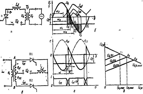
Rice. 3 Schemes of a single-phase (a) and two-phase (c) inverter driven by the network; time diagrams of currents and voltages (b, d), a family of inverter input characteristics (e).
Neglecting losses in the circuit, we can write
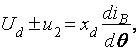
where x d - loop reactance.
It follows from the equation that the rate of change of current i Bwill be directly proportional to the differenceU d -u 2.
If , , current i B increases (Fig. 3b). At U d -u 2 = 0 i B reaches a maximum at U d -u 2 < 0 i B is reduced and maintained by the energy stored in the inductance of the inductor L d. The duration of the thyristor after the point O 1 is determined by the time during which this energy will be dissipated. The amount of accumulated energy is proportional to the areas S1 and S2, and scattered - S 1' and S2'. Therefore, the interruption of the current in the inverter circuit will be determined by the moment when, for a given control angle, both areas ( S1 and S 1' or S2 and S2') become equal to each other.
When changing the control angle in the direction of its decrease, the area S1 will increase all the time. Accordingly, the area should also increase. S 1'. However, the growth of this area at the indicated values U 2m and U d limited to a section of a sinusoid O 1 ...O 1". As soon as the entire reserve of this area is used up, the thyristor, once turned on, will no longer be able to turn off, and from the point O 1' its current will begin to increase again under the influence of voltage U d -u 2> 0, the inverter will go into short circuit mode. Dot O 1 ', which determines the boundary of the stable operation of the inverter, is called the boundary,
The loss of stability by the inverter (rollover) in real inverters occurs earlier than it is determined by the point O 1", since in order to restore the locking properties of the thyristor after it is turned off, a certain period of time () is required for the absorption of electric charges in p-n- transitions. Therefore, in a real inverter circuit, the thyristor must turn off earlier by an angle than the point is reached O 1", and this advance must always correspond to the heaviest operating mode of the thyristor, in which = max .
A similar picture can be obtained if = const, a U d= var.
The considered circuit contains the same elements as a controlled rectifier operating on counter-e. d.s. However, the role of counter-e. d.s. in inverter mode does not U d , and AC voltage. In order for this to take place, it is necessary to change the sign during the transition from the rectifier to the inverter mode U d and increase the control angle beyond the boundary.
The relationship between the main parameters of the circuit does not change, and, therefore, the operating mode of the inverter will be described by the same equations as the operating mode of the controlled rectifier, with the difference that the source U d acts in this case not as a consumer, but as a generator of active power. Due to this source, all losses in the inverter are covered. Thus, denoting your own e. d.s. inverter in idle mode through U d we get:
where U x and U a - reactive and active voltage losses.
In a grid-driven inverter, U x >> U a. The simplest single-phase mains-driven inverter has very poor energy performance due to poor utilization of the output transformer and significant current waveform distortion on both the AC and DC sides. For this reason, grid-driven inverters are usually poly-phase.
On fig. 3, c, g represented two-phase inverter circuit and timing diagrams of currents and voltages explaining its operation.
Selection of the required sections of the operating voltage, at which the sequential passage of current by thyristors is ensured IN 1 and IN 2 within each of the periods of alternating voltage, is achieved by choosing the moment of unlocking the thyristors using control pulses. When a control pulse is applied to the thyristor IN 1 shortly before the phase voltage BUT becomes negative, this thyristor unlocks and passes current mainly at a negative phase voltage BUT.
Counter direction negative voltage e 21 with respect to anode current i 21 indicates that this phase is receiving power from a DC source. This power in the process of current transformation is transmitted through the secondary and primary windings of the transformer to the single-phase current network. The same power transfer occurs in the next half-cycle through the phase AT secondary winding, when through it and the thyristor IN 2 current flows.
Transition (switching) of current from the thyristor IN 1 for thyristor IN 2 occurs in the same way as in the rectifying mode, for a certain period of time, called the switching angle .
The role of thyristors during current inversion is reduced to the role of switches that alternately close the DC source circuit to one of the secondary windings, namely the one that provides the most negative voltage in a given part of the period. In order for natural switching of the current to take place, characterized by the transition of current from one thyristor to another, the unlocking of the next thyristor must occur with some lead against the beginning of the negative half-cycle. This lead in angular measurement is called lead angle.
The advance angle must be sufficient not only so that natural switching of the thyristor currents can take place (angle ), but also so that after switching the currents there remains a sufficient angle before the appearance of a positive voltage, during which the thyristor that has completed its work must have time to recover its locking properties.
If the post-switching angle is less than required to restore the blocking properties of the thyristor, then with the appearance of a positive voltage at the anode of the thyristor that has finished working, it is unlocked again, and the current continues to flow with a positive half-cycle of the alternating voltage, which leads to the inverter tipping over.
So for normal operation the inverter is necessary to
![]()
![]()
where is the lead (control) angle, measured from the point of intersection of the phase voltages towards the lead; t voss - the recovery time of the control properties of the thyristor.
The ratio between currents and voltages for the slave inverter can be obtained from the ratios for a similar controlled rectifier circuit, in which the value ( - ) is substituted.
The expression for calculating the inverter current is:

The average value of the inverter input voltage (intrinsic back-emf) is summed from the no-load voltage and the voltage increment during the switching period:
![]()
The open circuit voltage is determined by the expression:
 (1)
(1)
The voltage increment due to the switching phenomenon is:

or as a function of the input current
 (2)
(2)
From expressions (1) and (2) we obtain the expression for the input characteristic of the inverter:
It can be seen from expression (3) that, in contrast to the external characteristic of the rectifier, where the second term determines its decline with increasing current, for the inverter, the second term determines the rise of the input characteristic. Boost input voltage U d b with increasing input current I d b is due to the addition of a switching pad to the sinusoidal open circuit output voltage.
On fig. 3, d the family of input characteristics of the inverter is given. The starting points on the y-axis correspond to the open circuit voltage. The upper limit of the characteristics is determined by the values of the currents at which the post-switching angle at a given angle becomes min, i.e., an angle sufficient to reliably restore the blocking properties of the thyristors (). points A 1 ,A 2 , A 3 on the input characteristics correspond to the limiting load currents I d b max and limit stresses U d bmax. Determining the limiting characteristic of the inverter.
X Typical features of inverter mode the following:
a) the inverter can only be built on controlled valves, since a positive voltage is applied to them for most of the non-working interval;
b) opening angle a must exceed 90°;
c) the polarity of the voltage on the DC side is opposite to the polarity of the rectifiers;
d) over the entire range of load current and input voltage variation, the following condition must be met: > + min .
STANDALONE INVERTERS
inverter a device for converting direct current into alternating current with constant or adjustable output voltage and frequency is called. If the inverter works on a load that does not have another power source, it is called autonomous. Autonomous inverters (AI) are used to supply consumers with alternating current from batteries or other direct current sources, for an electric drive with frequency regulation, in direct energy conversion systems, for example, from fuel cells, MHD generators, etc.
Basic requirements for AI: maximum conversion efficiency, minimum weight and size indicators and cost, controllability U n and I exit within a fairly wide range, providing a given form of output voltage, the absence of disruptions in the event of overload and idling, etc.
As switching elements in autonomous inverters, transistors, conventional and two-operation thyristors have been used. The former are used in devices of relatively low power, the latter are most convenient in voltage AI and regulated inverters. Ordinary thyristors sometimes have to be used in conjunction with forced switching circuits.
All AI can be subdivided into a number of types. According to the conversion scheme, AIs differ in the number of phases, the power circuit and some other parameters, which will be mentioned below. According to the method of switching valves, they can be as follows:
inverters, fully switched by control circuits (on transistors and bunkers);
inverters with switching capacitors connected in parallel with the load;
serial inverters;
AI with two-stage switching, allowing to regulate the output voltage.
However, the most significant division of autonomous inverters into two types is autonomous voltage inverters (AVI) and AI current (ANT) depending on the nature of the power source and its connection with AI (in addition, there are resonant AIs, but they are rarely used).
Autonomous voltage inverter.
AIP generates an alternating voltage in the load by periodically connecting it to a voltage source due to the alternate switching of the valves in pairs (Fig. 1, a).
The power supply operates in the voltage generator mode (battery or rectifier with a capacitive filter), the purpose of the capacitor will be explained further.
Rice. 1. Autonomous voltage inverter (a) and diagram of its operation (b)
The valves must be fully controlled (DOT) or each thyristor is supplied with a forced switching circuit. When the circuit is operating on the load, rectangular voltage pulses are formed (Fig. 1, b), and the shape of the current depends on its nature. If the load is purely active, then the shape of the current coincides with the shape of the voltage (dotted line in Fig. 1, b),
if the load is active-inductive, the current i n varies exponentially with time constant 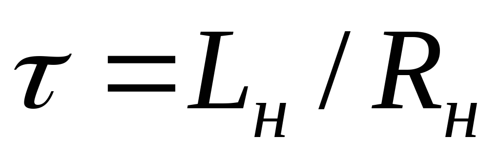 . When closing another pair of valves (for example, VD1
and VD4
)
and unlocking the second pair of voltage U n changes abruptly, and the current for some time
. When closing another pair of valves (for example, VD1
and VD4
)
and unlocking the second pair of voltage U n changes abruptly, and the current for some time  keeps its direction. To ensure the passage of this current, so-called flyback diodes are used. VD5...
VD8,
then the current is closed through the capacitor FROM.
keeps its direction. To ensure the passage of this current, so-called flyback diodes are used. VD5...
VD8,
then the current is closed through the capacitor FROM.
The frequency of the current in the load is determined by the control circuit, the load characteristic of the AVI is rigid, since the voltage at the load is almost equal to U n = E.
Since the input current of the inverter itself becomes (at RL- load) alternating, then when the AVI is operating from a rectifier, a capacitor is required FROM large capacity. AIN can operate in a wide range of loads - from idle to the value at which overloading of the valves is possible.
The maximum value of the load current with a symmetrical nature of the output voltage is
 ,
,
Where  ;;T- period.
It is possible to regulate the voltage at the output of the AIN, either by changing E, or with the help of pulse-width regulation. The latter is carried out in several ways: 1) each voltage pulse in the load is formed from several, changing their duration (Fig. 2, a); 2) reduction of the AVI operating time in each half-cycle due to the closing of one pair of valves and switching on the second pair with a delay (Fig. 2, b); 3) the use of two inverters operating for a common load through a transformer with a geometric addition of output voltages by adjusting the phase in the control circuits (Fig. 2, c). In the first two cases, the amplitudes of higher harmonics increase, but in the first variant it is possible to obtain an output voltage close in shape to a sinusoidal one.

Rice. 2. Voltage regulation in AIN
Autonomous current inverter.
AIT (Fig. 3) receives power from the power source through a sufficiently large inductance, so the current consumed by the inverter practically does not change. When alternately switching pairs of thyristors (not lockable), rectangular current pulses are formed in the load, and the voltage shape depends on the nature of the load, which, as a rule, is active-capacitive. According to the way the capacitor is connected to the load, AITs are called parallel.
As can be seen from fig. 3, at the next switching of pairs of thyristors (for example, they worked VD1
and VD4,
and are switched on by the control circuit VD2
and VD3
) through the load, the current changes abruptly, and due to the recharging of the capacitor FROM for a certain time interval, the previously working thyristors are under reverse voltage and, of course, are locked. It is necessary that this interval be longer than the turn-off time of the thyristor. The larger the time constant 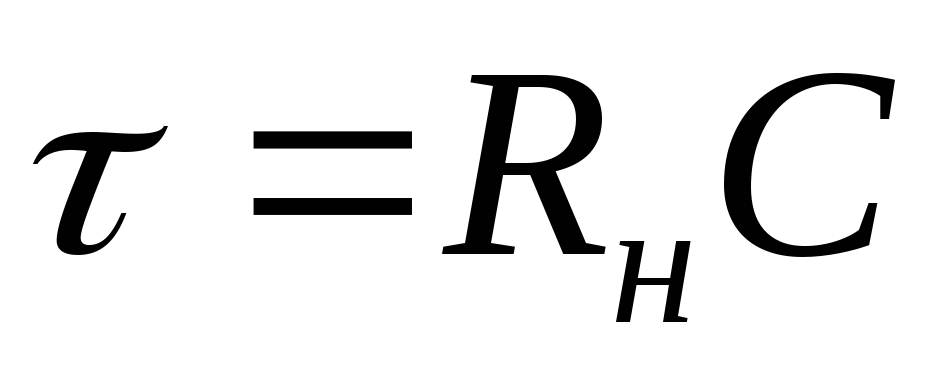 ,
the slower the voltage at the load changes, the law of its change approaches a linear one, and the shape approaches a triangular one. The external characteristic of AIT is soft (steeply falling), idle mode is impossible.
,
the slower the voltage at the load changes, the law of its change approaches a linear one, and the shape approaches a triangular one. The external characteristic of AIT is soft (steeply falling), idle mode is impossible.

Rice. 3. Autonomous current inverter (a) and diagram of its operation (b)
The relative value of the voltage on the load and the type of external characteristic can be approximately found from the formula
where  -
Efficiency AIT;
-
Efficiency AIT;  .
.
It should be noted that with an active-inductive load, the AIT is inoperable and such a load must be shunted with a capacitor.
Since in practice it is difficult to provide  for AIT or
  FROM for AIN, real circuits have some intermediate qualities.
To power a relatively low-power single-phase load with a voltage that differs markedly from the supply voltage, it is convenient to use a circuit in which one pair of thyristors is replaced by half-windings of the transformer, and it allows you to match U n and U n(Fig. 4).

Rice. 4. Parallel transistor inverter
When enabled, for example, VD1 current flows from the power supply through L, half winding W1 transformer Tr and VD1. An EMF is induced in the secondary winding, and a current appears in the load. Switching Capacitor FROM is charged almost to double the mains voltage (due to self-induction EMF in the winding W2). When the SU control circuit turns on VD2, capacitor is connected in parallel VD1, it instantly locks (since voltage is applied in the locking direction) and the process repeats.
A voltage is generated in the load with a frequency determined by the control circuit. The voltage shape depends on R n(for large R n it is closer to triangular, at smaller R n - to rectangular), value - from E, transformation ratio and value R n .
Voltage on L equal to the difference between U c (recalculated to half of the primary winding) and E. In modes close to idling, the capacitor is charged with a constant current, and U c can reach large (much more E) values, which is dangerous for thyristors.
As a control circuit, you can use a transistor symmetrical multivibrator with emitter followers connected to the control electrodes of thyristors, powered by the same power source. The scheme is suitable for E= 12...250 V, I n= 1...50A, f=10...2000 Hz.
Series inverters are in some cases used to produce alternating current of increased frequency ( f= 2...50 kHz). They have a resonant chain, with the help of which the valves are switched. The circuit works as follows (Fig. 5). When a control signal is given, it opens VD1, current goes through L1, R n , FROM. In the next half cycle, VD2 and capacitor FROM, charged during the first half-cycle, is discharged after R n , L2 and VD2. The circuit can operate in several modes.

Rice. 5. Sequential inverter (a) and its operating modes (b-d)
In the intermittent current mode (Fig. 5, b) VD1 turns off after the capacitor charge current drops FROM, i.e. until the moment when the control circuit includes VD2 (and vice versa). As a result, there is a time interval when both valves are not conducting current and I n = 0.
In the continuous current mode (Fig. 5, d) VD1 turns off when turned on VD2, i.e. there is a state when both gates conduct current. Shutdown VD1 in this case, it is carried out due to the fact that when the VD2 and the passage of the discharge current FROM through L2 in L1 back-EMF is formed, sufficient to reduce the current of the open VD1 down to zero. This requires that the inclusion VD2 happened when the current through VD1 already started to decline. Otherwise, the mode of "through" current through VD1, L1, L2 and VD2 , i.e. short circuit mode.
The optimal is the boundary mode (Fig. 5, c), in which the shape of the current in the load is close to a sinusoid. It is expedient to use such inverters at constant values of all parameters, including the load, while providing a fairly rigid external characteristic. Since the inverter may drop out of the mode at low loads, in parallel R n include FROM 0 and the inverter becomes series-parallel.
If you add another capacitor FROM 1 , then the inverter from a single-cycle turns into a two-stroke, at the time when it charges FROM, discharged FROM 1 and vice versa. This improves the efficiency of the circuit.
Series inverters can also be multi-phase.