Buy universal motherboard bios programmer. Restoring the BIOS on the programmer after an unsuccessful update
I was inspired to write this chewed material by my own recent experience, as well as by a rather meager and spread over the Internet infa on a necessary issue.
There are 3 main ways to recover a corrupted BIOS
1. Restoration by software of the motherboard itself.
Modern models of motherboards (Gigabyte has had the last 3 years on mainstream and top ones for sure) 2 BIOS chips are soldered on the board at once, in case of an unsuccessful update, the BIOS will boot from the backup mikruha, and later upload a copy to the damaged one. Some models do not have the ability to recover a damaged BIOS, and in the event of the death of the first one, the second one simply starts to work in its place, respectively, after the death of the second, the mother will no longer start
There is still the possibility of recovery from boot block"but it works if the BIOS is not completely dead and the bootblock is still alive and when trying to start the system it detects a crooked BIOS sum. In this case, it tries to read the BIOS from the HDD, or flop. Some boards (Gigabats have this feature) write a BIOS duplicate on the HDD, which is connected to them very first, respectively, this disk can be connected for recovery.To restore from a flop, it is enough to write the firmware with the correct name to a floppy disk, it will be detected and restored.The viability of the bootblock can be determined by signals (light and sound) from the connected flop guide, if the flop shows signs of life, then we got off lightly
2. Hot swap recovery or hotswap. It works only on mothers where the BIOS is not soldered, but sits in a socket and can be picked up. Those. you need to find another working board with a similar BIOS, i.e. so that the bed is the same and preferably the chips are common or one of the similar families, then the procedure will definitely work. On the board with a live BIOS, conveniences are made in advance for pulling the chip out of the bed - threads, insulated wire, etc. if there are no special tongs, the board turns on, we go into DOS (or the board's proprietary utility) to update the BIOS, tear out the BIOS, insert the dead one and flash the BIOS, if there are warnings about checksum mismatches, then ignore them, because there is nothing to be afraid of - the native BIOS lies separately. Then the system is turned off, we return our chip to each board and check the performance. This method will probably not work if the microcircuits are soldered into the boards, hot swapping will not work, of course you can take a chance and solder the BIOS on a working board - but this is very risky - you can be left with 2 already completely dead boards, and the electronics will already be dead, and not software part
3. Recovery on the programmer. This method is universal, i.e. You can flash any chip in any type of package. If the mikruha is soldered to the board, then remove it and solder it onto the programmer board or use special sockets. Of course, a limited number of microcircuits can be flashed on one programmer, but this usually applies to simple programmers, more "adult" ones are really universal, but they no longer cost 5 kopecks and are purchased mainly for streaming repairs, and not home use in order to restore a couple of boards. Nevertheless, this method is universal, it completely replaces and expands the first 2 methods, and when they do not work, this is the only way out. The hot-swap method is even an artificial method, which was discovered empirically due to the unification of board elements by manufacturers. I want to talk about one of the simple "home" programmers.
The essence of the process
I got my hands on a board the other day AsRock N68-PV-GS, gave it to me by the previous owner just like that. It has long been unsuccessfully stitched and was corny replaced by another. But I'm not used to throwing away equipment that can be restored by altering one microcircuit and undertook to revive the board - it will not be superfluous in the economy, the platform is still not so ancient, socket AM2
Lucky for me, the BIOS chip was MX25L4005APC-12G- 4 megabit mikruha in DIP package. Those. didn't even have to solder it. BIOS version 1.0 was on the manufacturer's website as a separate file of just 512kb (4Mbit/8=512Kb), i.e. the task is trivially simple - build a programmer, put a mikruha on it and sew it up! What I decided to start
Programmer circuit
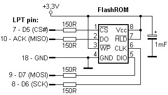
This chip is SPI type, which allows you to flash it with an elementary programmer through the LPT port. The corresponding programmer was found on the net immediately with software for its use, it is called SPIPgm, i.e. SPI Programmer, . The most elementary circuit of 4 resistors, a capacitor and an 8-pin socket is optional. Its limitation is actually a limited list of supported microcircuits - they must be 8pin and be of the SPI type
The programmer supports a lot of mikruhs, here is what is stated for the latest version 2.1 at the time of writing:
AMIC
A25L05PU/PT (64kB), A25L10PU/PT (128kB), A25L20PU/PT (256kB), A25L40PU/PT (512kB), A25L80PU/PT (1MB), A25L16PU/PT (2MB), A25L32PU/PT (4MB), A25L64PU /PT (8MB), A25L512 (64kB), A25L010 (128kB), A25L020 (256kB), A25L040 (512kB), A25L080 (1MB)
Atmel
AT25F512B (64kB) AT25DF021 (256kB) AT26DF041 (512kB) AT25DF041A (512kB) AT26F004 (512kB) AT26DF081 (1MB) AT25/26DF081A (1MB) AT25DF081 (1MB) ), AT25DF161 (2MB), AT25DQ161 (2MB), AT25/26DF321 (4MB), AT25DF321A (4MB), AT25DQ321A (4MB), AT25DF641(A) (8MB)
eon
EN25B10 (128kB), EN25B20 (256kB), EN25B40(T) (512kB), EN25B80 (1MB), EN25B16 (2MB), EN25P32 (4MB), EN25P64 (8MB), EN25P128 (16MB), EN25F10 (128kB), EN25F20 ( 256kB), EN25F40 (512kB), EN25F80 (1MB), EN25F16 (2MB), EN25F32 (4MB), EN25F64 (8MB), EN25F128 (16MB)
ESMT
F25L004A (512kB), F25L008A/08PA (1MB), F25L016A/16PA (2MB), F25L32PA (4MB), F25L64PA (8MB), F25S04PA (512kB), F25L08PA (1MB) (8MB)
GigaDevice
GD25Q512 (64kB), GD25Q10 (128kB), GD25Q20 (256kB), GD25Q40 (512kB), GD25Q80 (1MB), GD25Q16 (2MB), GD25Q32 (4MB), GD25Q64 (8MB)
Intel
QB25F016S33B8 (2MB), QB25F032S33B8 (4MB), QB25F064S33B8 (8MB)
macronix
MX25L512E (64KB), MX25L1005/1006E (128KB), MX25L2005/2006E (256KB), MX25L4005/4006E (512KB), MX25L8005/8006E (1MB), MX25L1605/1606E (2MB), MX25L3205/3206l/320LA, MX25L3205/320LA, MX25L3205/320LAMLA. (8MB), MX25L12835E/12836E (16MB), MX25L25635E/25735E/25835E (32MB)
PMC
Pm25LV512(A) (64kB) Pm25LV010(AB) (128kB) Pm25LV020 (256kB)
Spansion
S25FL004A (512kB), S25FL008A (1MB), S25FL016A (2MB), S25FL032A (4MB), S25FL064A (8MB)
ST Microelectronic/Numonyx
M25P05 (64kB), M25P10 (128kB), M25P10AV (128kB), M25P20 (256kB), M25P40 (512kB), M25P80 (1MB), M25P16 (2MB), M25P32 (4MB), M25P64 (8MB), M25P128 (16MB), M45PE10 (128kB), M45PE20 (256kB), M45PE40 (512kB), M45PE80 (1MB), M45PE16 (2MB), M25PX80 (1MB), M25PX16 (2MB), M25PX32 (4MB), M25PX64 (8MB), N25Q032A13E (4MB), N25Q032A11E (4MB), N25Q064A13E (8MB), N25Q064A11E (8MB), N25Q128A13E (16MB), N25Q128A11E (16MB), N25Q256A13E (32MB), N25Q256A11E (32MB), N25Q512A13G (64MB), N25Q512A11G (64MB), N25Q00AA13GB (128MB)
SST
SST25VF512(B) (64kB), SST25VF010(B) (128kB), SST25VF020(B) (256kB), SST25VF040(B) (512kB), SST25VF080(B) (1MB), SST25VF016(B) (2MB), SST25VF032( B) (4MB), SST25VF064C (8MB), SST25VF128(B) (16MB), SST26VF016 (2MB), SST26VF032 (4MB), SST26VF064 (8MB)
winbond
W25Q10B (128kB) W25X20 (256kB), W25X40 (512kB), W25X80 (1MB), W25X16 (2MB), W25X32 (4MB), W25X64 (8MB)
Motherboards that have a BIOS in the form of the above-mentioned microcircuits, I will not indicate for obvious reasons. It is much easier to look at the mikruha model and look at this list
Hardware
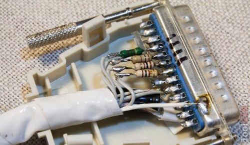
In my case, the memory I needed was on this list and I started making a proger. The device is very simple (it can be seen from the diagram) and many do not bother in such cases with etching the board, but assemble it by hanging mounting "on the knee", because. the programmer will be needed at most a couple of times. I also did not bother and made hinged. As a result, it didn’t work for me) Although it seems that I didn’t make a mistake anywhere, it was probably capricious due to the length of the wires or their cross section
For the second time, I already decided "to be sure" to drink myself normally, i.e. spread the board in SprintLayot 5.1 and made it using LUT technology. Ludil alloy Rosé. Recent times I like to use it because it turns out quite quickly, simply and tinning occurs in a uniform thin layer - the drilled holes do not close. A long time ago, I bought an enameled bowl for 30 rubles at a markdown in a utensil store - a good purchase for such cases) I pour half the water into it, bring it to a boil, add 1-2 tablespoons of citric acid (it works like a flux and raises the boiling point, then I lower the board and 1-2 pieces of alloy. I "control" the process with 2 ice cream sticks wrapped on one side in a cloth to rub the alloy over the board and hold the board. After the end of the process, the remains of the alloy can be removed for later use. The alloy costs a penny (about 150 rubles like) , but it is enough for such costs for years). In general, it was such a lyrical digression, now directly the screen of the divorced board. Samu
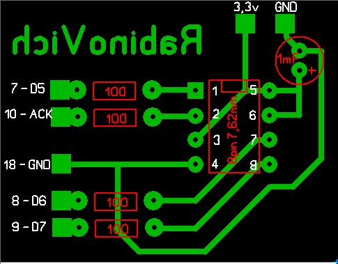
The board does not need to be mirrored, it is already "correctly" drawn. When I do the wiring, I will imagine the textolite as transparent - it’s much easier, at least for me
Required Ingredients:
- Resistors 150 ohm 0.125W x 4pcs
- Capacitive capacitor 1mF 16-63v x 1pc
- Socket 8pin 7.62mm x 1pc or special clamping panels for SMD chips, in general, depending on the patient
- Few wires, I used about 24AWG wires 12cm long
- Breadboard or textolite and all necessary accessories for its etching and tinning
- Pin connectors x 5pcs
On the wiring (as well as on the diagram), the pins to the LPT (DB25) connector are indicated by numbers, i.e. 7, 8, 9, 10 and 18. We need the first 4 contacts for data transmission, the 18th is the ground. But you can use for place 18 any in the range of 18-25. I deliberately did not place the DB25 connector on the board, because not everyone will do it. There are 2 reasons for that:
1. Few contacts, only 5 pieces, in order to spend 20 rubles on this connector and put it on such a tiny board. It is much easier to bring out these 5 pins and plug them into the connector itself
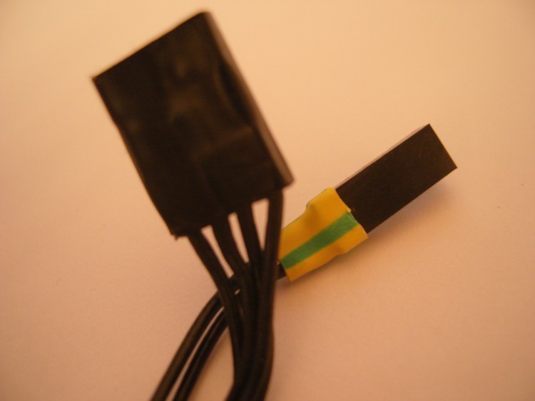
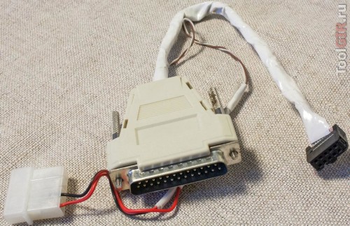
2. On modern boards, they no longer install a full-fledged LPT connector, manufacturers display pins on the board, to which you can connect an external / internal adapter and thereby get a DM25-F, i.e. LPT. Thus, having made a full-fledged programmer on board with DB25-M, we will have to make an appropriate connector for the board or buy an adapter separately, as board manufacturers advise. Of course, I have such an adapter ↓↓↓, I didn’t buy it, I made it myself from a floppy cable and a DB25-F connector taken from an old printer cable. But nevertheless, I did not bother to block this connector on the programmer simply because I did not have it at hand and also for the reasons of point 1

Homemade LPT adapter for modern boards. The flop's IDE connector is great for board pinouts, I inserted a piece of toothpick as a limiter so as not to miss for sure
I made it easier, brought out 5 contacts (I have 6 in the photo because 2 grounds) for the board pins corresponding to the connector, checked the board layout (in fact, all boards are the same, maybe only the "key" - the empty pin is in a different place , and in the marking manual go in a different order) and set them to the correct places, the programmer just conveniently uses the range of connector contacts 7-10 . I stuck the earth on conclusions 23 and 24, because 18-25 Earth
As a result, we should get something like the following device:


To power the programmer, you need a constant power supply of 3.3v, as well as an external mass. I use an external full-fledged PSU Gembird 400W for these purposes. I have it like a laboratory PSU, I would not trust it with a live configuration due to its quality) I got it from one good man- this PSU apparently does not have enough real power and the previous owner did not have enough of it, the system worked very unstable. This poor thing is enough for me for such things)
At the PSU on the 24pin connector, the green wire is closed to the ground, which makes it possible to start it idling, from the same connector I take 3.3v (orange wire) and ground (black) for the programmer
You can also use the BIOS battery as an option, it is just 3.3v, and take the ground (mass) from the body of the working PSU
Another option is to put some kind of stabilizer on 3.3v, for example LM1117, we supply 5v from USB and ground to the extreme contacts (I don’t remember the exact pinout, I used this stub in my other article about the drive connector for X "360), we will have 3.3v from the central one. In this way we get power from the SA itself, to which we are flashing - you can connect a USB connector or bring out 2 pins to connect again to the USB contacts On the board itself, after looking at the pinout
Software part
After manufacturing the device, you can proceed to the point for which all this was started - to the firmware
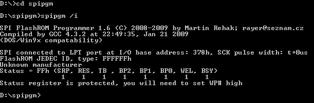
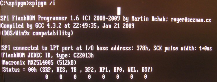
Current version SPIpgm 2.1 supports the whole family of desktop OS Windows, Linux and even DOS. I doubted very much that Win7/Vista everything will work, LPT programmers for this OS are very whimsical. nevertheless, everything coincided with the statement of the developer. do not forget that UAC must be disabled (I have it disabled and so "by default"). We turn off the PC completely, connect the programmer, turn it on and use the command line. With the help of an operator cd go to the desired directory where the programmer is located. Because we are in a Windows environment, then we need to use spipgm w , spipgm used in DOS and Win9x, however spipgm w can also be used in Win9x. The screenshot below shows that there are no problems, the programmer and software work perfectly in a modern environment, which is extremely rare in such tasks.

However, I note that I sewed in DOS, I'm so used to it) The simpler the OS, the more reliable it is. But I'm not campaigning to switch to it completely) It's just that for such things, using DOS is somehow more interesting for me. Based on my experience with other self-made programmers, I can say that this programmer will no doubt work in WinXP
If the programmer cannot recognize the microcircuit (see the screen below), then it is either dead, or the programmer is not assembled correctly or the power is not supplied, there is no mass. The second option is more likely
Here is what the command line will answer if the programmer is not assembled correctly. The chip is not recognized, i.е. failure
Mutim DOS or "I'm not looking for easy ways"
DOS is not so difficult to file yourself. You can simply make a bootable floppy using the Windows OS itself by formatting the floppy and putting a folder with the programmer and new firmware there, booting after the BIOS (on a working PC) into the console, use the programmer
The second option is to make DOS on disk or use the ready-made DOS 6.22 image. That's just the programmer itself will need to be written to a separate USB flash drive, because. if we take a dump, then it will not be able to write to the disk, although if reading is not required, you can roll it directly to the disk with the DOS image
The third option is to create a bootable USB flash drive, this is the most convenient and modern option for today. Good way described, for example,
I can also recommend using the MultiBoot project - a multiboot flash drive. In the end, we get a very functional tool for all occasions, such a powerful resuscitator. DOS is also there with support for NTFS, long names and more. Instructions for creating are present there, everything is very convenient and legal
We will assume that we launched DOS (owners linux this is not necessary, there is a SPIPGM file for them without extension) We go to the command line, go to the programmer folder. To learn the basic commands, we simply execute spipgm
In DOS, everything was recognized without problems too.
The main programs that we need:
spipgm /i- chip identification in the programmer. If the programmer is made and connected correctly, then the microcircuit (if it is in the list above) is recognized and, accordingly, it will be possible to continue working with it
spipgm /d dump.rom
- reading the contents of the chip to a file dump.rom
spipgm /e- complete erasure of the contents of the chip, it is recommended to do before recording
spipgm /p new.rom
- firmware, writing data to the chip from a file new.rom- a whole and correct firmware file for a specific motherboard, you can take it from the manufacturer's website or remove it from another chip of a similar board
spipgm /u- unlock, i.e. unlocking the chip for writing, if such protection is available
In total, in order to accomplish our plan in order to restore the BIOS, we need to execute a sequence of commands:
1. spipgm /i- we identify ourselves
2. spipgm /u- unlock
3. spipgm /e- erase the chip with crooked content
4. spipgm /p new.rom
- sew the correct firmware
! I draw your attention to the fact that if we do everything in the Windows environment, then instead of spipgm we use the team spipgm w
After that, we cut down the PC through the shutdown button and turn off the programmer
Attention! All manipulations with the LPT port must be performed only with the board powered off. Those. before connecting or disconnecting anything from the LPT, you must completely turn off the PSU, put the PSU switch in the position Off(or remove the cable) wait 10 seconds (capacitors will be discharged) and only then connect or disconnect something. If you don't follow this simple rule, then there is a great chance to be left without LPT, he is very capricious to such things due to his insecurity
Afterword
In total, now my board has been restored and received a second life. I will use it as a test and service ground for testing other kits. My readers will now also be able to revive something that has been lying around for a long time and was waiting in the wings.
I also draw your attention to the fact that this method is also suitable for restoring the BIOS not only on motherboards, but also on video cards, as ATI/AMD so nVidia. Many microcircuits that are indicated above in the compatibility list are also installed on video cards, but they are always soldered to the video card, so you will need the SMD soldering skill to restore the video. There are usually 2 options here - soldering the mikruha and installing it on a pre-etched programmer pad or soldering with wires to the video adapter board itself
I hope my experience will help someone save money and hardware, because it would not be entirely reasonable to apply for such services in the SC - such a fee in the secondary market is comparable to the cost of repairs, and therefore you need to either restore it yourself or go to the store for a new one. If I have the opportunity to dig into the programmer and BIOS "s with 20-pin chips (they are in square beds), then the material will be supplemented. Thank you for your attention
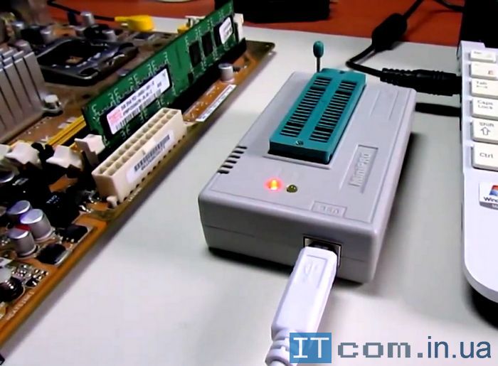
In this article I want to show how to flash the bios chip of a desktop computer motherboard using the TL866 programmer. We will try to make this article as informative as possible and invest the maximum amount of information in a short period of time. In this case, we will flash the BIOS chips of the Asus P5Q motherboard in the deep package. So let's get started.
What do we need to do to get started?
With the help of an extractor, remove the chip. You can try with tweezers, but since the contact pins of the microcircuit are very weak and can easily be bent, try to do this as carefully as possible.
Here is the extracted chip, it looks like this. Chip manufacturer Winbond 25x80va11z.
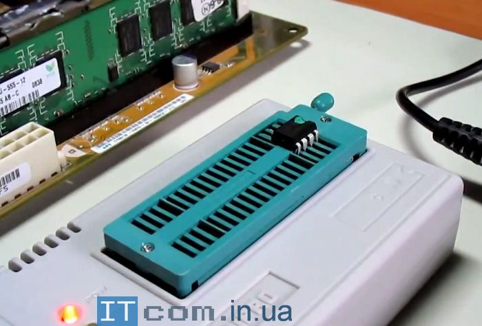
In order to flash it, in this case, a special block is not needed. Installing the microcircuit in the block in accordance with the key.
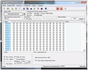
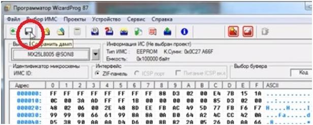
In order to start, let's go to WinPro program with which we will flash.
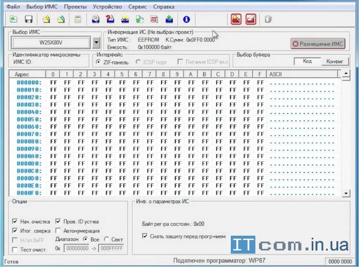
Select a chip in the "Chip Selection" window. In this case, we have a Winbond 25x80 chip.

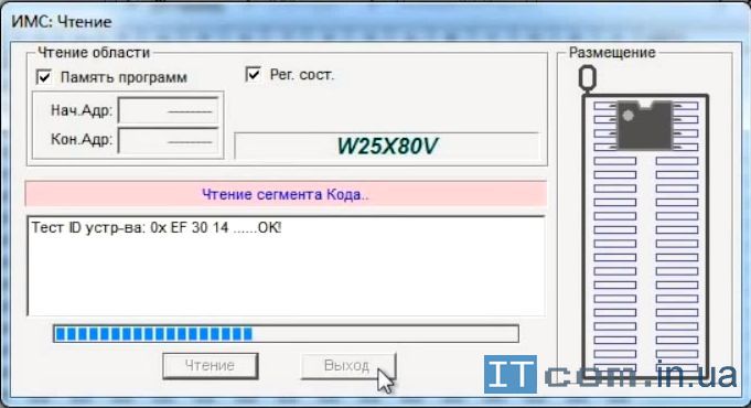
Click on the "Select" button and then you need to read it.
The chip is read and click on the Exit button.
It is necessary from the official website of the motherboard manufacturer. Firmware with ROM extension.
Before flashing, we need clear the chip.
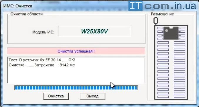
If the cleaning was successful, now we need to upload the downloaded firmware directly to the chip itself.
Select the file - open - look for the saved firmware.
Click "IC Programming".

We press the "Record" button and the microcircuit begins to be flashed.
Programming completed.
We install the BIOS chip in the reverse order. be extremely careful with the compact pins of the bios chip
Add a comment
Write full comments, answers like "thanks for the article" are not published!
In this video we will look at how to flash the motherboard BIOS via MiniPro TL866CS programmer.
The BIOSMSI motherboard is under repair. Model MS7392 version 2.
This motherboard needs a BIOS update. It must first be downloaded from the official MSI website.
It is stitched through the Chinese programmer MiniPro TL866CS.
Before flashing the board, you need to install drivers for this device.
Then we place the BIOS chip in the block, if required. Then, holding the lever, into the programmer itself.
Then we go to the programmer program.
To do this, select Autoselect 25 series and click Test.
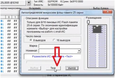
The program prompts you to select the desired chip.

In this case, it is the MX25L8005 in a SOP8 package. Select and press the Select command.
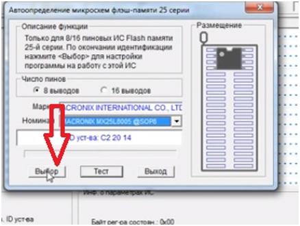
The microcircuit is displayed, now you need to read the information.
Click Read from IC
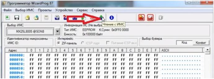
and again Reading.
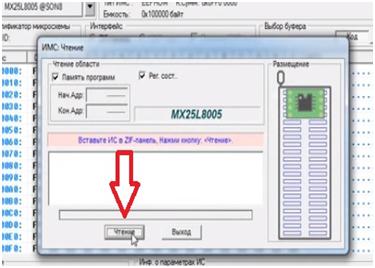
After the reading is over, we see the firmware that is available on this BIOSe. We save this information.

click Clear

In general, cleaning occurs during programming, but for insurance, it is better to first clean the chip using this function.
This helps to immediately track down possible problems.
Now open the pre-prepared firmware. Click File, open.
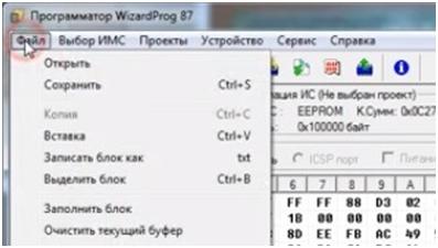
The firmware has an extension of 230.

This extension reads software and this programmer.
Not so long ago, something bad happened to me. It was necessary to update the BIOS on the motherboard, but an error occurred during the firmware, the system hung and stopped responding to any commands. After a forced forced reboot, the computer turned on, turned the coolers, but nothing was displayed on the screen and there were no sound signals. On the face of the damage to the BIOS when writing.
A little background:
Motherboard ASUS Commando, without, now fashionable, Dual BIOS. Only boot block- a small area of the BIOS that is not affected by the entry, which allows, if necessary, to initialize the minimum set of components necessary to turn on the computer, to search for the BIOS on removable media. Usually, a Floppy or a flash drive with a firmware file renamed to AMIBOOT.ROM (depends on the BIOS and motherboard, more precisely written in the instructions for the board) or a CD with drivers from the delivery kit are suitable. Having found a suitable file, the boot block will write it to the BIOS and, if everything went right, the computer will come to life after a reboot. Not a bad feature, it helped out several times, but in this case it did not work, apparently, the boot block was also damaged.
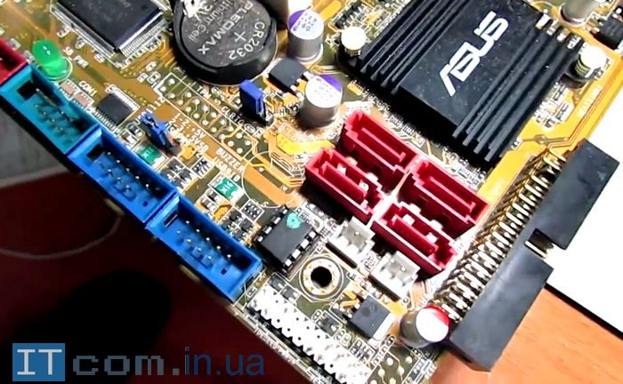
I had to look for other solutions. Since I didn’t have a soldering station and a stationary programmer for various eeproms in my arsenal of tools, I had to look for more affordable solutions. Examining the board, I found a small connector on it SPI_J1, and the flash memory chip is just with the SPI interface. A search on the Internet showed that there are quite decent factory devices and a lot of homemade products for flashing SPI microcircuits via USB (I don’t even talk about universal programmers with SPI support, that goes without saying). True, a search in local stores, SCs and forums, unlike Google, did not give anything, but I really did not want to order and wait a month.
A little more searching, and here it is, the solution - the Czech comrade (in Czech) about an extremely simple programmer and software for flash memory chips with SPI interface! Nothing complicated, a minimum of components.
Technically, this is a very simple method, and requires only a basic understanding of circuitry, the ability to solder a couple of wires and use the command line (cmd). But if you are not confident in your abilities, it is better not to risk it. In addition, you can always ask a friend who is friendly with a soldering iron.
Device Assembly
For assembly we need:
- 1 DB25P connector, can be cut off unnecessary printer cord
- 4 things. resistors by 150 ohm
- 1 any electrolytic capacitor with a capacity of 100uF or more and operating voltage on 6.3 V or more (Needed when powered by PSU)
- A piece of flat plume with IDC 10 pin connector (it is ideal if there is an SPI connector on the board)
- Plug molex(as on ATA hard drives) or CR2032 battery slot
There is nothing scarce, everything can be found in a pile of rubbish or for a penny in any radio store. In the worst case, you can try to get by with a few pieces of wire altogether by connecting the SPI contacts directly to the LPT, however, in this case, you need to be extremely careful, and it is difficult to guarantee the correctness of the recording.

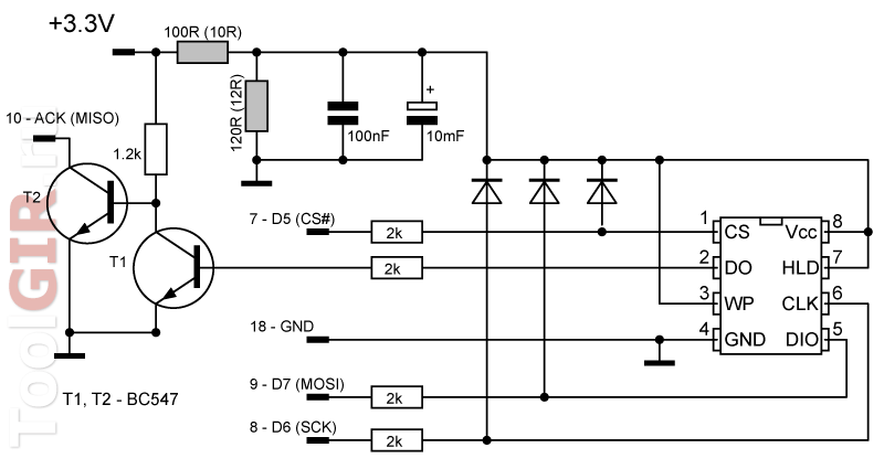
The SPIPGM programmer can also be used for flash memory chips with an operating voltage of 1.8 Volt. For this, the author uses an additional module (a kind of adapter), which is connected to the main module and consists of additional resistors for damping the voltage and an amplification stage on BC547 transistors for the output signal of the chip (diagrams on the author's websites at the link above). Below is an adaptation of the connection scheme, immediately designed to work with 1.8V chips. To obtain a supply voltage of 1.8 Volts, a voltage divider is used (gray resistors in the diagram, preferably 1/4 watt), the divider, if desired, can be converted to other denominations (I indicate options of 10 and 12 Ohms, or 100 and 120 Ohms), and also better replaced with a suitable DC-DC converter (eg TLV70018). Any diodes, they are needed to minimize errors and, in principle, you can do without them.
We will connect the programmer not to the chip, but to the connector SPI_J1.
If the connector is 7-pin, then connect to it as follows:
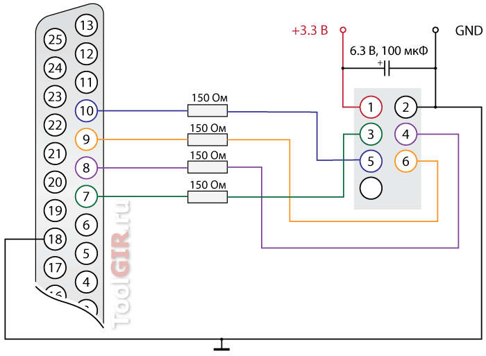
1. -> power supply +3.3v
2. -> ground from power and pin 18 on LPT
3. -> resistor -> LPT 7
4. -> resistor -> LPT 8
5. -> resistor -> LPT 10
6. -> resistor -> LPT 9
Likewise, on some motherboards ah, there are 9-pin connectors, the connection scheme is slightly different there:
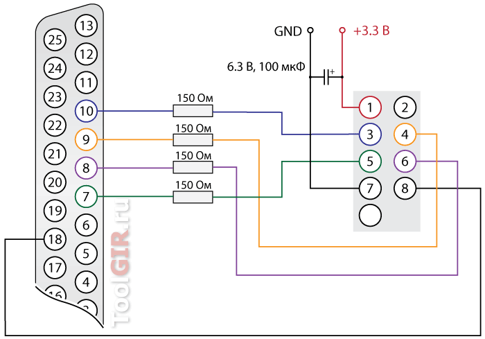
The good thing about the DB25P connector is that you can place all the necessary parts inside it. It is advisable to use the shortest possible cable length, otherwise there will be recording errors. It would be nice to close the wires with a screen, either from the antenna cable, or simply wrapping it with foil from a chocolate bar, remembering to connect the screen to ground (GND).
When powered by a battery, the capacitor can be omitted. Personally, I took with +5 power supply rails ( red wire), connecting to it through the connector molex and extinguishing the voltage with diodes up to ~ 3.3v (two or three diodes will be enough).
The power supply is still more reliable than batteries. Having a separate PSU can be powered directly from the bus +3.3 ( Orange ATX connector wire). To start the power supply without a computer, you need to close green and black wires.
Complete device:
SPIPGM Program
Now you can move on to the software.
The program supports a large number of chips ( full list in the Readme.txt file) and, according to the author, it works faster than analogues. You can download the latest version from the author's website, or from here:
By the way, the project is still developing to this day, the author often uploads updated versions of the program with information about new chips, improvements and corrections.
The archive contains the following files:
SPIPGM - Linux executable
SPIPGM.EXE - executable file for DOS/Win9x
SPIPGMW.EXE is an executable file for Win9x/NT/2k/XP/Vista/7 ( only x32, no x64 support)
IOPERM.DLL - low-level access library for Win9x/NT/2k/XP/Vista/7 (without UAC)
It's safest to flash from DOS by booting from Hiren or any other suitable bootable CD/Flash. But you can also from Windows.
Syntax and basic commands:
Syntax: spipgmw /<команда>[file name] [address] [size]
Basic commands:
i– flash memory identification
d filename– read the contents of flash memory into a file
p filename- write flash memory from the firmware file (without erasing)
v file name- compare the contents of the flash memory with the firmware file
e– complete erasing of flash memory
b- check for erasing flash memory
u– unlock write protection (depends on WP# signal)
File name — full name file, for example: file.bin, file.rom etc. The extension does not play a role, the main thing is that it is a correct image file and the name is correctly specified.
BIOS flashing via SPI:
spipgmw /i– chip identification. To check if everything is connected correctly, the program must determine the type of installed memory. If this does not happen, check the correct connection and the support of the chip by the program.
spipgmw /d BIOS.bak– if you want to keep a backup copy of your existing BIOS.
spipgmw /u– recording permission.
spipgmw /e- erasing.
spipgmw /p FILE.rom- write firmware ("FILE.rom" - the name of the firmware file, you need the file to be in the same folder with the program)
... waiting for the recording process ...
spipgmw /v FILE.rom- compare the recorded data with the firmware file. Or you can make a dump spipgmw /dtest.rom and compare its contents with the original firmware file in some Hex editor.
There may be a small number of errors. Depends on cable length, power stability, memory type. Of course, it is desirable that there are no errors at all, but even with a certain number of errors, the computer will most likely start up, and there you can already flash the BIOS using standard tools.
This method is suitable not only for flashing the BIOS of motherboards, but also for any other devices that have an SPI connector, or directly, for any supported microcircuit.
Any modern digital technology, both computer and household, works according to a specially written algorithm of actions. This algorithm, in the form of program code, is written in a special program, otherwise called device firmware. Sometimes, for example, in the case when the equipment was turned on without a surge protector during a thunderstorm, this firmware crashes.
Dual Bios SO-8
The program code that was written to the Flash memory of the chip starts to malfunction, and the device can no longer function normally. How to be in that case? Read the instructions on the site and find out. And here we need to find the firmware, in other words, the same program, in the format necessary for flashing, clear the chip's memory, and then overwrite the new program again. In order to upload the firmware to the memory of the microcircuit, we need a programmer. Sometimes, if a device was released with a raw firmware, flashing it to a newer one will add new features to the device, or get rid of unpleasant bugs that poisoned your life when using this technique. Let me give you a simple example: on motherboards, the manufacturer has provided the ability to update the firmware by simply reading it from a USB flash drive, going into the BIOS and selecting .
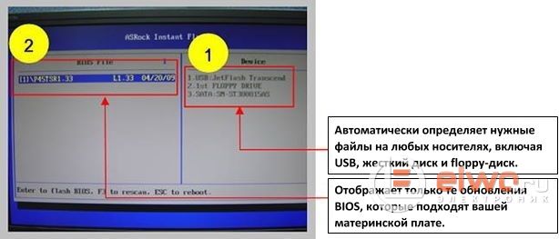
Then a reasonable question will arise for beginners, why do we need any other programmers at all, if everything is solved so easily and simply in the BIOS? The fact is that this is possible only when we can go into the BIOS and select the desired option, or in other words, when the motherboard is somehow functioning with us. The motherboard, in case of problems with the BIOS, can supposedly start when you press the power button on the PC, but there is no image telling us that the motherboard self-test was successful, either. How to be here? Did the firmware crash with us in this case, or something else?
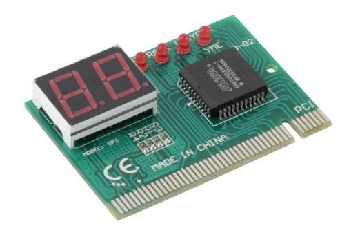
POST card
Here you first need to make a digression and talk about what a POST card is and why it is needed here. This is a special board for the PCI connector, which is plugged into it, and has an indication of POST codes, or in other words, an indication in the form of an alphanumeric code of ongoing software processes, the activation of the motherboard, on two seven-segment indicators. These POST codes, of course, each have their own decryption, by which we determine, in the event of a breakdown, at which stage we failed. And now, if we see that testing freezes on one of the POST codes, we can assume with a certain degree of probability that the faulty BIOS is to blame for the malfunction. Of course, before flashing, you must first perform all the standard procedures in case of poor contact in the memory or processor connectors.

Processor socket
Insert the processor into the socket, raise and lower the lever 20 times, while the oxides, if they were on the socket contacts, will be erased. Go over the RAM contacts with a soft white eraser, on both sides, for the same purpose. Take a toothbrush and swipe 5 times over each of the memory slots, along the connector, along it. As practice shows, sometimes this is enough to make the computer work.
By the way, if you changed the battery on the motherboard, do not forget to clear the CMOS by shorting for 10 seconds, 2 Clear CMOS pins on the motherboard with a jumper.
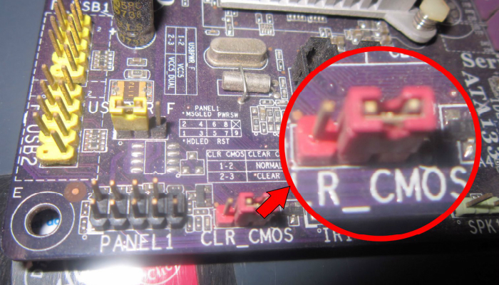
How to reset CMOS
If the motherboard was an Asrock model, such as the widespread N68 or G31 series, and the like, then you will need to remove the RAM modules and reinsert them, after replacing the battery, read about shadow RAM, who are interested in what this is for.
If you still need to reflash
So back to our sheep). You have done all these procedures, but the motherboard, as before, does not want to work properly, and you decide to flash the BIOS. Here you need to know what types of microcircuits and in what cases you can meet on motherboards. We will not specifically consider the types of memory chips that were found on outdated motherboards from the Pentium 4 era in the PLCC32 package. They need a different type of programmer, much more difficult to manufacture, and expensive in cost if bought ready-made.
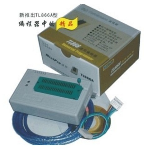
Programmer TL 866A
If someone really needs to flash such a memory chip, you will need the TL 866A programmer, which can be ordered from Ali Express, this is just the programmer itself, without adapters and adapters, and it will cost about 2.5 thousand rubles. The complete set will naturally be more expensive. But as it turned out, there is an even cheaper solution to this problem, although less universal. This is a NANO USB Programmer, from E-bay, on Ali Express, for some reason I did not find it.

NANO USB programmer
The decision to purchase it, due to its lower versatility, compared to the TL866A, is probably very controversial, but it also costs about half as much, about a thousand rubles. We are now interested in memory chips with an SPI interface, which require much cheaper and simpler programmers.
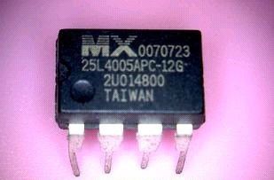
ddip-8 bios chip
The fact is that starting around 2007, on motherboards of AMD and Intel platforms, a gradual transition began from BIOS chips, in the PLCC32 package, to chips with an SPI interface, having 8 legs, and produced in Dip-8 and So- eight.
BIOS PLCC
The latter, as you already understand, are released in the SMD version. So, these same microcircuits, on modern motherboards, are very often produced in a Dip-8 package, and are installed in a special socket.

Programmer CH 341A
In this case, we just have to remove the chip from the socket, install it in the ZIF adapter of the programmer, flash it, and then install it back into the motherboard. By the way, before erasing the chip and flashing it with new firmware, be sure to save the current firmware on your hard drive. This will allow you to upload it back without any problems, in case the new firmware does not work stably, or is not suitable for this device at all.

But where can I get the firmware for the programmer, because it should be in *. bin or *. hex, it is these firmware formats that the programmer understands, and on the official website of the manufacturer to update the firmware via a USB flash drive, you can only download some generally left incomprehensible format. As practice has shown, this is most often the same binary format *. bin, only with a different extension, and to flash it we just need to change the file extension to *.bin. How simple does it all seem...
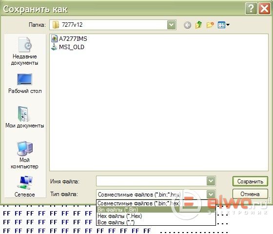
But it wasn’t there, they rejoiced early) ... For example, manufacturers of firmware do not upload open access to monitors and other equipment, and access to them is available only in service centers, or you can ask someone to take a dump from a working monitor. But fortunately the world is not without good people, and these firmware, if you search very well, can still be found on specialized sites for the repair of equipment. What if the BIOS chip is in our SO-8 package? Is it necessary to solder it before flashing? No, at least not always ... The Chinese industry produces a special adapter, a clip, by attaching it to the contacts of the microcircuit from above, we can flash it without soldering. But I will make a reservation, this option does not always work.
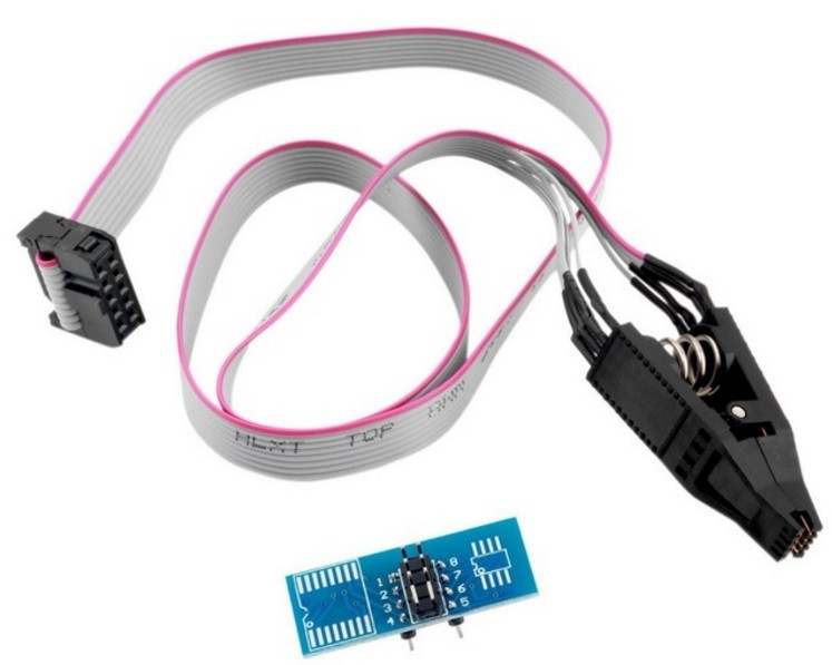
In this case, you will need to unsolder the memory chip and flash it by soldering it to the adapter pad, or use a clip, holding the chip into it, or with such adapters that have different widths of the installed chip, 150 and 200 mil.
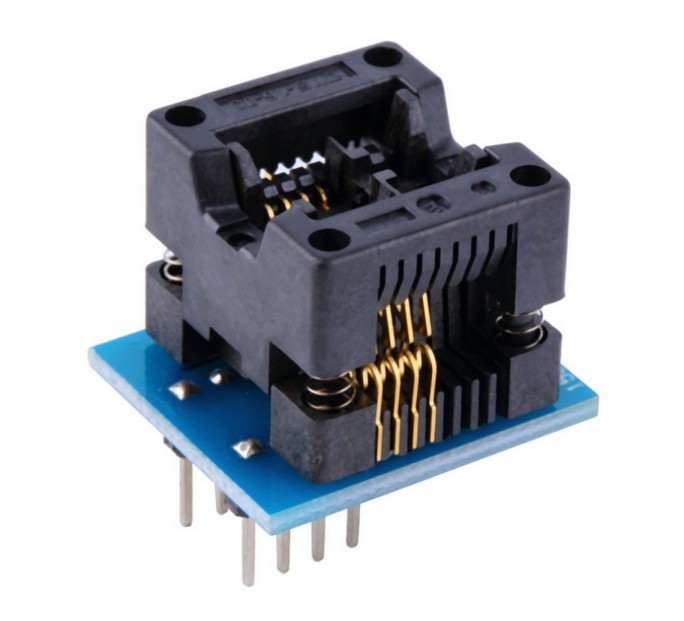
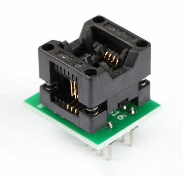
Adapters 200 and 150 Mil
How can you desolder an SO-8 chip without using a blow dryer? You can use Rose or Wood's alloys, in extreme cases, you can take a lower temperature solder than lead-free solder, POS-61, apply it to the contacts of the microcircuit, take a stainless steel medical needle, and pry it under one of the contacts of the microcircuit, warming it with a soldering iron tip , lift it up.

Then this procedure must be done alternately with all contacts. After that, you need to remove the old solder from the contact pads on the board, applying the flux, using a dismantling braid. I recaptured my programmer and clip a long time ago, having flashed the BIOS on just one motherboard. And now he often helps me when there are doubts about what the problem is, in the BIOS or not. If, for some reason, it is not possible to purchase an SPI programmer, you can solder a simple circuit yourself, for flashing microcircuits in a Dip-8 package, most likely for one-time work, it will be enough for you.
Electric scheme
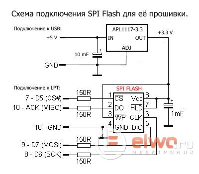
A 3.3 volt stabilizer, in this case, if there is an emergency, you can replace a tablet with a lithium battery, 2016-2032, it, of course, fresh, gives out about 3 volts, and such power will be enough for one-time firmware.
Instead of output
This conditional - software repair of motherboards is one of the simplest types of repair, and does not require any experience in soldering, or the presence of a soldering gun, and other expensive tools and devices. I recommend the SPI programmer from Ali Express, and the clip for it, as an inexpensive solution for flashing the BIOS of motherboards, to all novice masters who cannot afford to purchase the TL866A programmer for various reasons. All successful repairs, AKV was with you.


