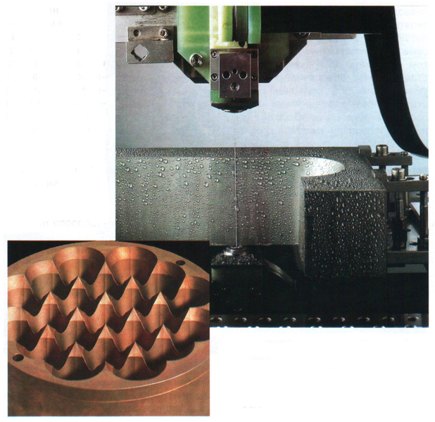
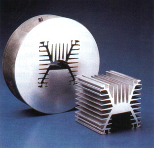
Electroerosive machining of a large number of holes. Benefits of cutting metal with wire
The essence of electroerosive machining is to remove the allowance from the workpiece in a dielectric medium due to microdischarges that melt metal particles.
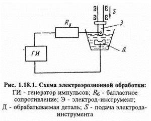
The process of electrical discharge machining (EDM) is the destruction of a metal or other conductive material as a result of local exposure to short-term multiple electrical discharges between two electrodes, one of which is a workpiece, and the other is an electrode-tool (EI). Under influence high temperatures in the discharge zone, heating, melting and partial evaporation of the metal occurs - electrical erosion. To obtain a high temperature in a limited area of small removal, a large concentration of energy is required. This goal is achieved by using a pulsed voltage, and EEA is carried out in a liquid medium that fills the gap between the electrodes, called the interelectrode gap (IEG), or the interelectrode gap. The scheme of electroerosive processing is shown in fig. 5.1. The electrodes, one of which is a workpiece 1, and the other is a tool 2, are connected to an electric pulse generator and immersed in a dielectric liquid 3. When the electrodes approach a sufficiently small distance, a breakdown of the interelectrode medium occurs in a place with the highest electric field strength. The dielectric strength of the gap at the breakdown site is broken, and a thin conductive channel 4 is formed, which closes the electrodes. A current pulse of high density flows through the formed conductive channel, the discharge channel expands, and the temperature in the discharge zone reaches several thousand degrees. The sections of electrodes 5 and 7 in the discharge zone melt and evaporate. Under the influence of high temperatures, the liquid in the discharge zone decomposes and evaporates and, together with metal vapors, forms a rapidly expanding bubble 6.
Fig 5.1 - Scheme of electroerosive processing
With a decrease in the current passing through the electrodes, the vapor pressure in the expanding gas bubble drops. As a result of a decrease in pressure, the molten metal boils and is ejected in the form of small drops 8 in environment(liquid), where it solidifies in the form of small particles. Solid erosion products are removed from the interelectrode gap under the action of shock waves and liquid flows caused by an electric discharge and the formation of a spherical bubble with its subsequent expansion. Holes are formed on the electrode surfaces at the place where the discharge passes. The dimensions of the dimples depend mainly on the energy and duration of the pulses and the electroerosive resistance of the material. To obtain dimensional processing, energy is introduced into the processing zone in separate portions in the form of electrical pulses of a sufficiently short duration. In the pauses between pulses, the working fluid restores its dielectric properties (deionizes). If a continuous supply of energy is carried out, then large volumes of material from one of the electrodes will be heated and melted, even if the electrode materials are the same. The material removal direction is determined by the polarity of the electrodes connection to the pulse generator and the pulse parameters. When a sinusoidal voltage pulse is applied to the electrodes (Fig. 5.2) in the 0 ... 1 section, the voltage will increase to U pr, at which the dielectric strength of the gap is violated. The average voltage at which the breakdown of the interelectrode gap occurs depends almost linearly on the size of this gap and is 40 ... 50V in finishing modes, and 70 ... 80V in draft modes. Section 1…2 corresponds to the spark stage of the discharge, for which
characterized by a rapid decrease in voltage across the gap to 25 ... 35V and an equally rapid increase in current in the circuit. Section 2…3 corresponds to the arc stage of the discharge, at which the voltage and current in the circuit slightly decrease. When the voltage U S drops below 15 ... 20V, the discharge stops. When treated with short pulses of high frequency, the arc stage of the discharge may be absent, and the discharge stops immediately after the spark stage. The amount of material removed at the arc stage of the discharge and the dimensions of the dimples formed are much larger than at the spark stage.
Rice. 5.2- Time diagrams of voltage and current changes in the electrode gap
The main technological indicators of the electroerosive machining (EDM) process - accuracy, surface quality, productivity - depend on the amount of metal melted from the baths in one pulse, which is determined by the pulse energy.
The pulse energy is found from the expression:
where ![]() - average current strength, A;
- average current strength, A;
The value of the current in the event of a short circuit (set according to the instruments of the machine);
![]() - average breakdown voltage, V;
- average breakdown voltage, V;
Open circuit voltage with open electrodes (controlled during processing);
Pulse duration (inversely proportional to their repetition rate), C.
Depending on the technological conditions, the pulse energy can be estimated according to the recommendations of Table 5.1.
Table 5.1 - Pulse energy values
EDM of a profiled cavity. Switching on reverse polarity. 1 - workpiece, 2 - discharges in the gap, 3 - electrode-tool, 4 - process current pulse generator.
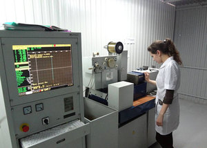
Processing the workpiece on an electroerosive copy-piercing machine. The workpiece is in a working bath filled with working fluid.
EDM(abbr. EEO) - Processing, which consists in changing the shape, size, roughness and properties of the surface of an electrically conductive workpiece under the influence of electrical discharges arising between the workpiece and the electrode-tool.
One of the electrodes is a workpiece, the other is a tool electrode. Discharges are produced periodically, pulsed, so that the medium between the electrodes restores its electrical strength. To reduce the wear of the tool electrode, unipolar process current pulses are applied. The polarity depends on the pulse duration, since at a short pulse duration, erosion (wear) of the anode predominates, and at a long pulse duration, erosion (wear) of the cathode predominates. In practice, both methods of supplying unipolar pulses are used: with the workpiece connected to the positive pole of the pulse generator (the so-called direct polarity connection), and with the workpiece connected to the negative pole (the so-called reverse polarity connection).
Types of EEE
- Combined electrical discharge machining -- performed simultaneously with other types of machining
- Electroerosive-chemical machining (EECM) - combined electroerosive machining, carried out simultaneously with the electrochemical dissolution of the workpiece material in the electrolyte
- Electroerosive abrasive processing - abrasive processing using electroerosive destruction of metal
- Anode-machining is electrochemical processing in a liquid medium, in which the material of the electrode-workpiece is dissolved under the action of electric current with the formation of oxide films on the treated surface and their removal by mechanical action.
Can be followed by electroerosive machining
- Electroerosive hardening - electroerosive processing, which increases the strength of the surface layer of the workpiece
- Electroerosive volumetric copying - electroerosive machining, in which the shape of the surface of the electrode-tool is displayed on the workpiece electrode
- Electroerosive flashing - electroerosive machining, in which the electrode-tool, delving into the electrode-workpiece, forms a hole of constant cross section
- EDM marking
- Electroerosive cutting - electroerosive machining, in which the electrode-tool in the form of a continuously rewinding wire during the feed movement bypasses the workpiece along a given path, forming a surface of a given contour
- EDM cutting - EDM, in which the workpiece is divided into parts
- Electroerosive grinding - grinding using electroerosive destruction of metal
- EDM
- EDM with straight polarity
- Reverse polarity EDM
- Multi-electrode erosion machining
- Multi-contour processing
Characteristics of the electric discharge during EEE
The electrical discharge between the electrodes proceeds in several stages: first, an electrical breakdown occurs, which may be accompanied by spark discharges; then an arc discharge is established. Therefore, many generators are capable of outputting a multi-stage pulse shape.
The frequency of pulses and their duration is selected based on the technological requirements for the treated surface. The pulse duration is usually in the range 0.1 .. 10 −7 seconds, the frequency is from 5 kHz to 0.5 MHz. The shorter the pulse duration, the lower the roughness of the resulting surface. The average current during EEA depends on the area of the treated surface. With an area of 3600 mm², the optimum current is approximately 100.
Features of EEE
The tool electrode can have a fairly arbitrary shape, which allows processing closed channels that are inaccessible to conventional machining.
EEE can be exposed to any conductive materials. The main disadvantages of EDM are low productivity (feed rate is usually ~10 mm/min) and high energy consumption.
Story
Robert Boyle (1694), Benjamin Franklin (1751), Joseph Priestley (1766) Lichtenberg Georg Christian (1777): made the first reports on electrical discharges and the effects that accompany them.
In 1941, doctors Boris Romanovich Lazarenko and Natalya Iosifovna Lazarenko (Moscow State University) was instructed to find methods to increase the service life of ignition distributors for automotive engines.
As a result of research and experiments with tungsten, attention was drawn to the directed destruction by electric discharges created by pulses of a certain form of current, which served as an impetus for the creation in 1943 of a new technological process for processing workpieces using electroerosion.
In 1943, Soviet scientists, the spouses Boris Romanovich Lazarenko and Natalia Ioasafovna Lazarenko, proposed using the electroerosive properties of discharges in an air gap for shaping (electrospark method of electroerosive processing). The invention received an author's certificate No. 70010 dated 04/3/1943, French patent No. 525414 dated 06/18/1946, UK patent No. 285822 dated 09/24/1946, US patent No. 6992718 dated 08/23/1946 (the specified patent has a completely different date and subject), Swiss patent No. 8177 dated 07/14/1946, Swedish patent No. 9992/46 dated 11/1/1946 See also
Notes
Links
- GOST 25331-82 Electroerosive processing. Terms and Definitions
- Nemilov E.F. Electroerosive processing of materials. - L .: Mashinostroenie, 1983.*
14 September 2012
Parts and components of modern machines and devices are distinguished by a wide variety of designs and materials used, including those whose shaping by known methods of machining is difficult, and sometimes impossible. This is due to the increasing use of EDM processes. “The possibilities of EDM machines are endless!” - such a phrase can often be heard from machine users just a month after the equipment is put into operation.
Classification
According to the technological purpose, machines for electrical discharge (EE) processing are divided into two main types - copy-piercing and wire-cutting.
Copy-piercing machines allow processing shaped holes and cavities, internal and external surfaces of bodies of revolution, grinding, cutting. It is possible to obtain helical and involute surfaces, as well as various internal shaped holes and cavities with a straight, reverse and variable cone. In copy-piercing machines, the electrode-tool is shaped, its shape is a reverse copy of the cavity to be processed.
EE wire-cutting machines are used for the manufacture of parts for stamps, copiers, templates, shaped cutters, patterns and other tooling. The electrode-tool in cut-out machines is a continuously rewound wire. The design features of the machines determine their technological advantages: no shaped tool is required, no need to make corrections for electrode wear, it is possible to obtain small parts of complex shape, including parts with an equidistant profile (matrices, punches) using one CNC program.
Stages of progress
EE treatment both in the world and in our country is no longer an unconventional treatment method. Currently, EE equipment is the fourth most used in the world after milling, turning and grinding. Sales of EDM machines increased from 0.5% in 1960 to over 6% of the MEO market in 2000.
The priority in the discovery of electrical erosion belongs to Russia. The first practical research in this area was made in the Urals at the end of the 30s by the spouses B. and N. Lazarenko while studying the problems of contact erosion. The discovery was registered in 1943. The world's first EE cutting machine was manufactured at a factory in Fryazino, Moscow Region in 1954. But, unfortunately, the production of EE equipment in the Soviet Union did not receive proper development.
EE wire cut
EE cutting on wire-cutting machines appeared in the early seventies and is continuously progressing in several directions.
Cutting speed increased from about 10 mm 2 /min. in the early seventies up to 35 mm 2 /min. in the mid-eighties, and now has reached 330-360 mm 2 /min. The increase in speed was achieved primarily by washing the working surface with a liquid under high blood pressure and the use of more efficient pulse generators that allow you to install optimal parameters. The increase in speed is also facilitated by an improvement in the quality of the electrodes.
Reliable and efficient automatic wire threading, wire break prevention and automatic part loading have been developed to take advantage of high speed cutting and eliminate machine downtime.
Max Height matrices and punches of stamps, processed at the beginning on erosion machines, was in the range from 50 to 100 mm. However, for the machining of molds, extrusion dies, and various other parts, manufacturers of EDM machines have expanded the range of sizes of parts machined on them.
Initially taper hole angle, equal to 1° for parts with a height of 100 to 125 mm, was practically the maximum possible. To meet customer requirements, 30° angles with a workpiece height of around 400 mm can currently be achieved on most machine models.
Maximum achievable accuracy increased from 25 µm, which was typical for the first machines, to 1 µm - for modern EE machines. Much less effort is required from operators of modern cut-out machines to achieve machining accuracy of the order of 1 μm compared to experienced operators of the first cut-out machines, which received machining accuracy of the order of 5 or 2.5 μm.
This simplification of work to ensure increased accuracy due to the development of several factors. The technology built into the latest machines ensures that the required contour is cut exactly according to the geometric program. Optical rulers provide stable accuracy regardless of the duration of the machine and large temperature fluctuations.
The most important innovation is the equipping of machines with highly reliable and efficient automatic wire threading devices, which allow the processing of a number of parts without the participation of an operator. The ease of use of the machines makes it possible to increase the cost-effectiveness of machining and service more machines in the shop with less effort, even on a day shift.
EE firmware
The most significant improvement in CNC stitching machines compared to manual machines has been the reduction in processing cycle times, and above all, the reduction in operator time. In 1960, the processing of a cavity with a tool electrode required approximately 4 hours of operator work and 4.5 hours of electroerosion time. With the advent of CNC already in the mid-eighties, the required operator time was only 0.5 hours, and the erosion time was about three hours.
New stage of time reduction processing cycles began in 1999 by equipping copy-piercing machines with adaptive pulse generators. Compared to previous generations, these generators have the ability to optimize the machining process based on its continuous monitoring. Such a generator also adapts the current density during processing in roughing modes, which greatly contributes to an increase in the productivity of processing with electrodes of any shape. When machining in finishing modes, the system provides process control to protect the quality and uniformity of the machined surface using a more advanced sensor for contamination of the interelectrode gap. All this increases productivity by 10 times in comparison with the previous generators.
Businesses are turning to robotic machine loading systems to increase machine tool uptime. deserted mode, increasing productivity per machine and reducing tool change times. The robot is built into the machine, the CNC system provides direct control of the machine and the robot. Other benefits of this system are adaptive control, a 50% reduction in electrode change time and a reduction in floor space.
New control systems provide opportunities easier programming, contributing to the reduction operator hours. The typical control system allows the operator to perform offline programming on a personal computer and then download the program to the machine. This results in a reduction of approximately 25% in programming time and EDM time for most operators.
 Machining accuracy on copy-piercing machines largely depends on the accuracy of the electrode. The introduction of affordable high-speed milling machines for graphite electrode processing has made it possible for enterprises to simplify the task of efficiently processing a large number of precision electrodes.
The accuracy of the latest models of copy stitching machines has also been improved. This applies in particular to micromachining. For example, when electroerosive machining of square cavities with an area of 60 mm 2 using the latest pulse generators, a cavity profile with a corner radius of 0.025 mm is obtained due to a 65% reduction in electrode wear in these corners. This allows six times fewer electrodes to be used.
With increasing processing speed, size and shape complexity of workpieces, increased accuracy achievable, easier machine operation, unattended operation, user education, customer support and affordability, EDM has established its position in the tool industry and is increasingly being used in mainstream manufacturing. .
Today, no enterprise can ignore the possibilities of electroerosion, which can solve many production problems.
Turning directly to the analysis of EE equipment, let us dwell on several fundamental issues that significantly determine the effectiveness of EE processing.
Linear drives
EE feed drives of CNC machines are built according to the traditional scheme. More reliable and modern drives are made without a belt drive. In these drives, the power stepper motor is directly connected to the lead screw. The disadvantages of these drives are well known:
- a large number of intermediate elements from the energy source to the working body (RO);
- the enormous inertia of these elements, which is especially noticeable in large machine tools;
- the presence of gaps in the transmitting devices;
- friction of mating parts, which changes dramatically when the system moves from a state of rest to a state of motion;
- temperature and elastic deformations of almost all transmission links;
- wear of mating elements during operation and loss of initial accuracy;
- errors in lead screw pitch and accumulated length error, etc.
Since these shortcomings reduce the main quality characteristics of the drives (accuracy and uniformity of the stroke of the working body, the amount of backlash during reverse, permissible accelerations and speeds of the RO), the design thought of machine tool builders has long been trying to somehow reduce their influence. For example, instead of a lead screw with a nut, an expensive and complex ball screw connection is used to reduce friction; in order to eliminate gaps, special devices for tensioning the connection are introduced into the connection of the screw with the nut; lead screws of highly precise machine tools are made according to the standard class; screw pitch errors are reduced using compensators; Sophisticated cooling systems are created to combat temperature deformations. Nevertheless, it is clear that the problems of drives with lead screws cannot be solved in principle because of their physical and technical nature. 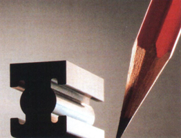 The task was to radically replace the typical drives of metalworking machine tools with some other ones. And such a solution was the use of linear motors (LD). The principle of operation of such an engine has a number of advantages: there are no intermediate elements between the energy source and the RO, energy is transferred through the air gap, nothing needs to be rotated, it becomes possible to implement the main task - the longitudinal movement of the RO. All elements of electroautomatics, electric brake systems, protection systems, special shock-type equipment, etc. have been working on this principle for decades. Vast experience in the use of electromagnetic systems has revealed their advantages: amazing simplicity of design and use, the possibility of almost instant stop and reverse, quick response, large forces generated, ease of adjustment.
The promise of the solution, of course, was immediately appreciated. There was only one thing missing - the possibility of regulating the speed of the RO in the electromagnetic system. And without this, it was impossible to use an electromagnetic drive as a mover for a RO machine.
Particularly intensive research in this direction was carried out in Japan, where the linear drive was first used as a mover for bullet trains. In the same place, attempts were made to create linear drives for metalworking machines, but the first developed samples had significant drawbacks: they created strong magnetic fields, overheated, and most importantly, they did not ensure the uniformity of the movement of the RO.
Only on the threshold of the new millennium, mass-produced machines (so far only EDM) began to be equipped with a new generation of LDs, which are distinguished by the uniform movement of machine carriages with ultra-high precision, a large range of speed control, huge accelerations, instant reverse, ease of maintenance and adjustment, etc. In principle, the design LD hasn't changed much. The engine consists of two elements: a fixed flat stator and a flat rotor with an air gap between them. Both the stator and the rotor are made in the form of flat, easily dismantled blocks. The stator is attached to the rack (base) of the machine, and the rotor to the working body. The rotor is elementary simple, it consists of a set of rectangular bars, which are strong permanent magnets. The latter are fixed on a thin slab of special mineral-ceramics, the coefficient of thermal expansion of which is two times less than that of granite, and the hardness is close to that of sapphire.
With or without bath
EE wire-cutting machines without a bath (cutting only in a jet) have been produced and operated for a long time. Machines without a bath are 15-25 thousand dollars cheaper than machines with a bath (plunge cutting). If the enterprise has a sufficiently large area of EDM machines, a part of the machines without a bath is a justified solution. If there is only one machine, it is worth considering what it should be.
Machines without a bath (jet) significantly limit the technological possibilities:
- it is impossible (or extremely difficult) to cut contours in parts such as a hollow pipe;
- it is impossible (or extremely difficult) to make contour cutting of multilayer slabs with voids between layers and in parts with holes, “pockets”, etc.;
- jet machines are suitable only for cutting parts of simple stamps, but do not provide stability of the environment of electric spark discharges on difficult tasks;
- only during blasting, the air cannot be completely expelled from the cavities, which leads to an increased formation of abnormal discharges and as a result to wire breaks, scrap, cutting instability;
- without a bath, it is impossible to ensure temperature stability if the room temperature fluctuates significantly during the day; this is especially dangerous when cutting dies of multi-window serial dies. In a water jet, taper cutting with angles greater than 15° is unstable at a large thickness.
Water or oil
Oil is a delicate and friendly medium for metal EDM. The high resistivity makes it possible to generate ultra-small spark discharges. The electric spark gap when cutting in oil is much less than in water.
In EE wire cutting, the tool size is the wire diameter plus 2 gaps. Since an EE discharge in water requires a larger gap, the size of the EE tool in water is always larger. In other words, for the same wire diameter, the resulting cut is wider in water than in oil. In addition, water is an aggressive medium for metal, which creates known problems. And these problems are all the more serious, the smaller the dimensions of the elements of the cut contour.
The main reason why water is used in EE machines is speed. Modern EE wire cut machines allow cutting at speeds up to 360 mm2/min. However, speed in microcutting is a secondary indicator.
Oil as an EE cutting medium is much more attractive than water. In addition to smaller gaps, the oil is completely free of electrolytic erosion and surface corrosion. The quality and durability of the tool surface after cutting in oil is significantly higher than after cutting in water. In oil, the cutting speed is stable even with a wire with a diameter of 0.025-0.03 mm.
Oil is an indispensable medium for EDM cutting of precision tools and small parts.
Manufacturers
The field of play (that is, the EDM market) is large and there are many players on this field, however, as the famous Dutch footballer Marco Van Basten said, 22 people play football, and the Germans always win. So in the production of EDM equipment, there are many manufacturers, and there are two clear leaders: the Japanese company Sodick and the Swiss AGIE Charmilles Group, which includes the companies AGIE and Charmilles. AGIE Charmilles Group and Sodick account for over 60% of global EDM sales.
The Russian market also includes products of such foreign companies as Fanuc, Hitachy, Mitsubishi (Japan), Dekkel, Diter Hansen (Germany), CDM Rovella (Italy), Electronica (India), Maurgan, Joemars Machinery (Taiwan), AOZT MSHAK ( Armenia)…
Expert opinions
Michael Riedel, Head of Special Tools Department at SCOB (Germany): “Because PKD (polycrystalline diamond) as a material has a hardness similar to diamond, almost all traditional processing technologies are not applicable to it. As a method of processing products from this material, only electroerosive action can be used.
Rudolf Eggen, director of Kroeplin GmbH (Switzerland): “There are three possibilities for manufacturing contact levers for linear measuring instruments: casting, laser cutting and electroerosive cutting. We chose EDM because casting with an annual production of 6,000 pieces per model is too expensive, and laser cutting does not achieve the required accuracy due to insufficient repeatability of the results. In addition, due to the short duration of preparatory and final operations and the high autonomy of processing during night shifts and on non-working days, EDM is more economical than other methods.”
Frank Haug, Managing Director of Frank Haug GmbH (Germany): “The possibilities of using EDM are endless. Our expectations for its usability and accuracy have been greatly exceeded. Thanks to this technology, today we can produce many products in tight deadlines.”
Walter Gunter, owner of Ganter Werkzeug (Germany): "Thanks to the rational use of EDM cutting, we can manufacture microtomes with high precision with their components from the best materials and meet the tough market requirements that unnerve our competitors."
Advantages of wire EE processing
New opportunities in the manufacture of parts
Various wire diameters and the high suitability of EE wire machines for processing internal shapes allow you to produce parts that are impossible with traditional processing methods:
- obtaining deep grooves;
- production of parts with minimum internal radii;
- production of die tooling with high precision without manual finishing.
Reduced processing time
Obtaining a finished part from a heat-treated workpiece without the use of intermediate operations, achieving the required surface roughness without the use of manual finishing, manufacturing parts from hard alloys, ease of mounting workpieces on the machine due to the absence of loads on the workpiece during processing - all these advantages can radically reduce manufacturing time and enterprise costs compared to traditional processing methods.
Savings are achieved through:
- material savings (whole waste, not chips);
- use of one machine with one tool for the manufacture of the finished part;
- no need for intermediate operations for heat treatment of blanks;
- the possibility of manufacturing thin-walled parts and parts from brittle materials without the use of complex and expensive tooling.
Reduced labor costs during machine operation
EE machines are designed for autonomous operation, which allows one operator to operate several machines at the same time.
Reliability and high accuracy
Due to the absence of mechanical loads on the workpiece and the constant updating of the tool - wire - the dimensions of the resulting part are not distorted. Each part, produced according to the corresponding program, can be repeated any number of times, changes in size or configuration can be made, if necessary, in a matter of seconds.
A bit of physics
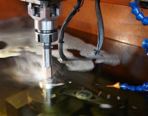
The principle of electroerosive machining is based on the destruction and removal of material by the thermal and mechanical action of a pulsed electric gas discharge directed to the treated area of the workpiece in the liquid. At the same time, complex physicochemical processes occur in the discharge channel, in the workpiece, in the working fluid and in the tool electrode, which determine the technological characteristics of the shaping process.
When the electrode-tool and the workpiece, immersed in the working fluid (dielectric or weak electrolyte), approach each other, discharges are initiated between them under the action of the pulse voltage of the generator. The formation of discharges depends on the processing mode. An electrical discharge is a pulse of electrical energy highly concentrated in space and time, converted into thermal energy between the electrode-tool and the electrode-workpiece. After the breakdown, a discharge channel is formed, surrounded by a gas bubble, both expanding as the discharge develops. When the electrode surface is bombarded with electrons and discharge ions, a concentrated heat release occurs, causing the appearance of holes with molten metal, some of which is overheated and can evaporate. A significant part of the metal is removed at the end of the current pulse due to a sharp decrease in pressure in the discharge channel, accompanied by mechanical impacts. Thus, electrical erosion of the conductive material is carried out.
The materials from which the tool electrode is made must have high erosion resistance. The best indicators in this sense are copper, brass, tungsten, aluminum, graphite. Working fluids must meet a number of requirements: low corrosiveness to the materials of the electrode-tool and the workpiece, high flash point and low volatility, good filterability, no odor and low toxicity.
Magazine "Equipment: market, offer, prices", No. 12, December 2001
Electrical discharge machining of metal is widely used to change the dimensions of metal parts without violating their physical properties. Such a process is carried out with the help of special equipment and requires a good knowledge of the necessary technologies.
In addition, such processing makes it possible to obtain holes of the desired shape and configuration, if necessary, to make shaped cavities, and to make profile grooves and grooves on workpieces created on the basis of hard alloys.
Such an electroerosive effect makes various tools much stronger, provides production of high-quality electroprinting, high-precision grinding, carry out cutting parts and more. Processing is carried out at full compliance all necessary rules safety technology.
Principle of operation
Before proceeding with this type of processing, it is first necessary to correctly assemble all the required elements into a single chain and pre-prepare the details needed for work. Today, industrial enterprises use different types electroerosive impact.
It should be noted that essential element in the scheme required for EDM, is an electrode that must have sufficient erosion resistance. In this case, metals such as:
- graphite;
- copper;
- tungsten;
- aluminum;
- brass.
 From the point of view of chemistry, this method of thermal action on the metal contributes to the destruction of its crystal lattice, due to which certain categories of ions are released.
Quite often, to process metal, they use electrospark and electropulse methods. There are also electrocontact and anode-mechanical methods.
If roughing is required for metal parts, then an electric pulse circuit is usually used. At the same time, during operation, the temperature of the generated pulses can reach 5,000 degrees. This increases such a parameter as performance.
If you need to process workpieces with small dimensions and dimensions, then the electrospark method is mainly used.
Electrocontact processing is used when working with alloys, carried out in a liquid medium. It should be noted that acquired metal properties after such exposure can affect the performance of parts in different ways.
Almost always, due to the influence of currents and high temperatures, the strength of the workpieces is greatly increased, and softness is preserved in the structure itself.
Types of equipment used
 It is known that there are various ways and methods of metal surface treatment, and this type is considered more effective than mechanical. This is mainly due to the fact that tool used for machining is significantly more expensive than the wire used in EDM.
Industrial enterprises for electroerosive metal processing use special equipment, such as:
- wire-electroerosive;
- copying and firmware.
If there is a need to produce parts with complex shapes and molds, as well as for the production of some materials with high machining accuracy, use wire-electroerosive aggregates. Most often, such equipment is used for the manufacture of various parts for electronics, aircraft, and even the space industry.
Copy-piercing units are mainly used for serial and mass production of parts. Thanks to such machines, fairly accurate through contours and small holes are obtained, which is successfully used in the manufacture of meshes and dies in the tool industry. Such equipment is selected focusing on goals and financial payback. Electroerosive machining of metal is considered a complex and rather time-consuming work process.
 Such work cannot be done at home. Only certified and qualified specialists with sufficient experience in this field have the right to perform work on machines for processing parts.
When performing electroerosive machining, do not forget about safety precautions and the use of overalls.
Advantages of EDM
Such work should be carried out only on special equipment under the obligatory supervision of a qualified specialist, having the appropriate permission. Although this method makes the workpiece more accurate and of high quality, industrial enterprises prefer to use metal machining.
Therefore, it is necessary to note the main advantages of electroerosive action on various types of workpieces.
Using this method, it is almost always possible to achieve the most High Quality the surface of the metal, as a result of which it becomes as accurate and uniform as possible. This completely eliminates the need for finishing processing. Also, this method ensures that the output surface of a variety of structures.
Also, the advantages of electroerosive metal processing include the ability to work with a surface of any hardness.
 Electroerosive action completely eliminates the occurrence of surface deformation in parts with a small thickness. This is possible due to the fact that with this method there is no mechanical load, and the working anode has minimal wear. In addition, electrical discharge machining helps to obtain a surface of various geometric shapes and configurations with minimal effort.
Also, the advantages of this process include the complete absence of noise when working on special equipment.
Of course there are disadvantages during electroerosive action on the part from metal, but they do not significantly affect its operational properties.
Processing technology
In order to fully understand all the advantages of electrical discharge machining and understand the principle of influencing a metal workpiece, the following example should be considered in more detail.
So, a simple EDM circuit must necessarily consist of the following elements:
- electrode;
- capacitor;
- capacity for the working environment;
- rheostat;
- power supply source.
This circuit is powered by a pulse-type voltage, which must have different polarity. Thanks to this, it is possible to obtain the electric spark and electric pulse modes that are required for operation.
 During the application of voltage, the condensate is charged, from which a discharge current is supplied to the electrode. This electrode is lowered in advance into a container with a workpiece and a working composition. As soon as the voltage on the capacitor reaches the desired potential, a breakdown of the liquid occurs. She is starts to heat up very quickly to boiling point
EDM wire cutting of metal- an electrospark processing method that allows processing internal through and external surfaces of complex shape, such as splined surfaces, surfaces of gear teeth, working surfaces of extruder dies, etc.
We carry out the development of drawings according to the provided sketches and samples
*The price does not include depreciation costs for equipment and tools, electricity, taxation of fixed assets. The cost of the material and its delivery to the metalworking site.
Detail drawing requirements
1. In the drawing, you must specify the material of the workpiece, all dimensions, tolerances and requirements for the surface after processing.
2. The drawing is made in electronic form and provided in vector format (Autocad, Corel, etc.)
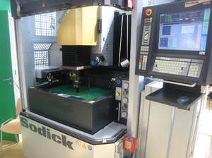
Machine equipment
For electroerosive machining of parts and materials using the electrospark method, our production uses a precision electrospark wire-cutting CNC machine of the brand Sodick AQ325LN1 with linear motors. The technical capabilities of the machine allow you to perform the following types of work:
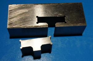
- production of equipment and devices (dies, templates, molds, dies, special tools) from high-strength materials with high accuracy;
- fine-tuning products to the required dimensions;
- high-precision curly cutting of metal (cutting holes of cylindrical and conical shape, cavities of complex shape, straight and profile recesses, slots and grooves);
- electroerosive processing of products of a cellular structure (grids, sieves, etc.);
- electroerosive machining of hard and heat-resistant materials and alloys with cleanliness up to 12 roughness class.
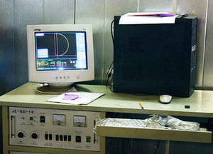
Operations are performed in automatic mode using a CNC controller with software, which controls the technological process, taking into account the many parameters that affect it (material characteristics, complexity of the part configuration, cutting conditions, etc.).
Electroerosive machining of metal can significantly reduce the number of operations for the manufacture of products, establish the production of parts of increased complexity that cannot be manufactured on modern machine equipment machining. Finished products do not need additional refinement of the surface quality, regardless of the thickness they are not subjected to deformation, the material retains all its physical properties. The accuracy of manufacturing parts by the electroerosive method is 1.5-2 times higher compared to traditional mechanical metalworking methods.
EDM production capabilities
The EDM wire cutter Sodick AQ325LN1 has the following specifications:
| Options | Values |
|---|---|
| Main dimensions, mm | |
| dimensions of the working surface of the table (length x width) | 600 x 400 |
| moving the table (length x width x height) | 350 x 250 x 220 |
| cone table travel in two planes | 80 |
| workpiece thickness with cutting method (jet / submersible) | 220 / 200 |
| Taper cutting angle | 20 o / 80 mm |
| Maximum workpiece weight, kg | |
| in jet cutting | 450 |
| in plunge cutting | 300 |
| Power consumption, kW | 6-8 |


