Download the drawing of the coupling in the compass. Friction clutches: principle of operation, drawing
We easily connect shafts: ASCON presents the "Library of Couplings"
Maxim Kidruk
Active replenishment of the ASCON product line in the field of design preparation for production continues. New applications enhance the power of the flagship product, the KOMPAS-3D V8 Plus 3D solid modeling system. Readers have probably already familiarized themselves with the Universal Mechanism Express library for the kinematic and dynamic analysis of KOMPAS-3D 3D models, with the long-awaited animation and photorealistic libraries. This article talks about another novelty that came out after the listed applications - the Coupling Library.
Accelerating the 3D design and construction process has always been a priority for developers of any CAD system. But despite this, the number of narrowly focused applied 3D libraries is not that great (there are significantly fewer of them than similar libraries for 2D design). For the most part, these are applications for automated modeling of bodies of revolution (shafts, gears) or technological equipment. And this is all the more surprising that 3D modeling in industrial enterprises is gaining momentum every year.
Appearance of the Coupling Library
Building large 3D assemblies is usually associated with a large number of routine operations. Many components that make up an assembly are not unique parts and are time consuming to create, slowing down design. These components include springs, bolts, nuts, dowels - in a word, everything that has long been described in the standards. To quickly build these components in the KOMPAS system, there are libraries of standard products that cover the widest range of fasteners, pipeline fittings, bearings, etc. But, you see, not only fasteners or other simple parts are standardized. Many much more complex mechanisms are manufactured and assembled in accordance with the requirements of GOSTs, OSTs, normals, etc. Modeling such mechanisms by hand is always a hassle for the designer, often taking much more time than designing and building models of unique parts. The Coupling Library provided by ASCON is an application that allows you to quickly create fairly complex models of machine-building couplings and use them in the developed assemblies for connecting shafts.
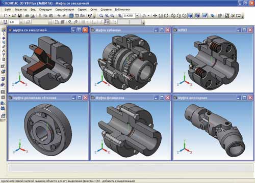
The first version of the “Coupling Library”, officially presented on July 3 this year, is intended for creating three-dimensional models (assemblies) or assembly drawings of a number of standard couplings various types. All standard sizes for any type comply with the standards, so the designer should not worry about finding and choosing the overall, connecting or other characteristic dimensions of the coupling he needs. The whole process of building a coupling model consists only in choosing the diameter of the shafts to be connected, pressing the OK button and inserting the coupling at an arbitrary point in the drawing or assembly. For almost all couplings in the library, there is a choice of different construction options (for long or short shaft ends, with a conical or cylindrical shaft hole, etc.), which also meet the requirements of the standards.

Using the application, you can create couplings of the following types:
1. Blind couplings:
Flanged according to GOST 20761-76;
Longitudinally rolled according to GOST 23106-78 (ed. 1990).
2. Rigid compensating couplings:
Toothed according to GOST R 50895-96;
With an intermediate movable element (with a sliding cracker, cross) and cam-disk according to GOST 20720-93);
Hinged small-sized according to GOST 5147-80.
3. Elastic compensating couplings:
Elastic sleeve-finger according to GOST 21424-93;
With rubber sprocket according to GOST 14084-93;
Toroidal rubber sheath according to the normal MN 5809-65.
4. Other designs:
Overrunning roller clutch (free running) according to OST 27-60-721-84;
Safety with shear pin.
When working with KOMPAS-3D 3D documents, the clutch model is inserted into the assembly as an editable macro element. This means that the macro object created by the library can be edited both manually, using KOMPAS tools, and through the library by double-clicking on the clutch model. When editing through the library, the user can not only change the size of the current coupling, but also replace it with any other. After editing, the newly created model will be placed at the same point in space and with the same orientation as the coupling that preceded it. The model can be built with or without a cutout.

As already mentioned, the Coupling Library can also provide significant assistance to engineers working in KOMPAS-Graph. In this case, the designer has access to all the same standard sizes and configurations of couplings as in 3D modeling, but a coupling can be inserted into a drawing or into a fragment in any of three views (main, side, top). The library provides the ability to automatically create cutouts in the main view or in the left view for almost all types of couplings. When inserting a coupling drawing into a graphic document, you can select the anchor point (the point that determines the position of the image at the time of movement and insertion), as well as disable or enable automatic setting of the characteristic dimensions of the coupling. Like a 3D model, the clutch image can be edited through the library, manually, or by dragging and dropping characteristic points (there can be from one to four such points, depending on the type of clutch).

Characteristic dimensions, selected from GOST, for the MUVP coupling
In both cases (for both 3D modeling and 2D drawing) the Coupling Library allows you to automatically create a BOM object. In addition, when building a 3D model, the user can change the color of any of the parts that make up a particular coupling. It should be noted that the selected colors, as well as any other settings changed by the user, are remembered by the program for the next library calls.
In addition to the characteristic parameters (transmitted torque, rotational speed, overall dimensions), the library contains information on all design dimensions for each type of coupling.
General information
"Compass" - a family of computer-aided design systems with the ability to design and design documentation in accordance with the standards of the ESKD and SPDS series.
Developed by the Russian company Ascon. The name of the line is an acronym for the phrase "complex of automated systems", the trademarks use capital letters - "KOMPAS".
compass coupling drawing detail
1. Description of creating 3D models of parts included in the assembly
Coupling 125-32-1-U3 GOST 14084-93 is an elastic coupling with an asterisk, designed to connect coaxial cylindrical shafts when transmitting torque from 2.5 to 400 N m and reduce dynamic loads of climatic modifications U and T, categories 1-- 3 and climatic versions UHL and O category 4 according to GOST 15150-69.
Couplings are made in two versions: 1 - on the long ends of the shafts; 2 - on the short ends of the shafts in accordance with GOST 12080--66.
Coupling drawing according to GOST:
Part requirements
Half coupling - Steel 35 GOST 1050-88
Asterisk - Rubber compound V-14 TU 005.1166-87
Fixing screw - Steel 10 GOST 1050-88
Locking ring - Steel 10 GOST 1050-88
Note: to simplify the creation of this coursework, libraries of chain coupling elements were used according to GOST.
2. Description of obtaining working drawings of parts from 3D models
1. Half coupling
To obtain a working drawing of the coupling half, open the coupling half detail in a separate window:
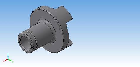
Further, to obtain a working drawing of the part, create in the Create menu, select Drawing, then select View from model - Standard in the Insert menu and place the coupling half drawing in the workspace. As a result, a drawing with 3 views should be created.
2. Asterisk
3D image of an asterisk:

3. Fixing screw
3D image of the fixing screw:

4. Retaining ring
3D view of the locking ring:

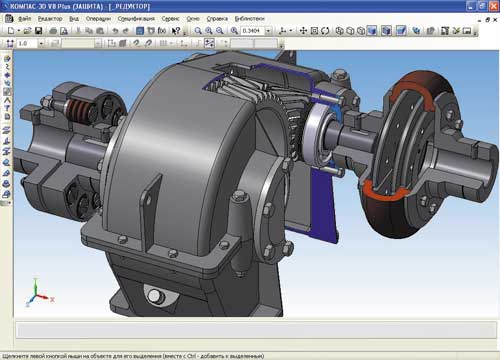
3. Description of creating a 3D assembly
Assembly - a model of a product consisting of several parts with a given relative position. An assembly can also include other assemblies (subassemblies) and standard items. The assembly file has the a3d extension.
In order to unambiguously determine the location of parts in the assembly and the possibility of their movement relative to each other, restrictions are imposed on them, depriving them of one degree or another of freedom. They are called conjugations. These are parametric connections between faces, edges and vertices of parts, their coordinate and auxiliary planes. (for example, the coincidence of the faces of two parts or the alignment of the sleeve and the hole).
In the KOMPAS-3D system, using the command buttons, you can set the following types of interfaces:
Parallelism. As a result of executing the command, two flat faces or planes of mating objects become parallel.
Perpendicularity. This command places two planar faces or object planes perpendicular to each other.
On distance. A user-specified distance is set between geometry elements.
Coincidence. This command combines user-specified elements
Touch. The contact of a round surface and a plane is performed.
At an angle. Mating objects are located relative to each other at a user-specified angle.
Alignment. The command ensures the placement of two round surfaces on the same axis.
The commands for applying mates are located in the group of commands on the menu Operations / Component Mates. The shortcut buttons for these commands are located on the Pairing panel.
The auto-mating mode allows, when moving components, to recognize elements approaching each other (faces, vertices, edges) and automatically add mates that correspond to their shape and type. For example, when flat faces approach each other, the system “on the fly” imposes a “coincidence” conjugation on them, and when cylindrical faces approach each other, it imposes a “coaxiality” conjugation.
Using the mating data and alternately assembling these parts into one coupling, the following assembly was created:

4. Description of obtaining an assembly drawing using 3D assembly
Technically, an assembly drawing is created in the same way as a working drawing of a part: views, sections, sections are generated automatically. But the format of these documents is different.
Assembly drawings include:
a) image of the assembly unit;
b) dimensions with maximum deviations, which are performed according to the assembly drawing;
c) instructions on the nature of the pairing of parts;
d) position numbers;
e) overall dimensions;
f) installation and connecting dimensions;
and) specifications products;
h) coordinates of the center of mass (if necessary).
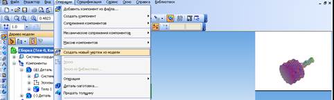
To create an assembly drawing, select Create new drawing from model from the Operations menu item. Let's save the file.
We place the position numbers of the assembly parts and indicate the overall dimensions:

5. Description of the receipt of the automatic specification
When working with a specification document in KOMPAS-3D, they usually use such a concept as a specification object.
A specification object is a string or several text lines in a specification document that characterize (describe) one material object: a part, a subassembly, a subassembly, etc.
When creating each model of a part that will be inserted into the assembly, care must be taken to enter information into the model, which will then be placed in the specification (name and designation of the part). This information is stored in the m3d file itself as a specification object. That is, each KOMPAS-Detail document must have its own subordinate specification object containing a single line describing the given detail.
If, when inserting a unique part into an assembly, on the Properties tab of the properties panel, the Create specification objects checkbox was selected, then all specification objects of each component will be automatically loaded into the assembly. And when using elements from the library, do not forget to check the Create specification object checkbox. For parts or subassemblies created in the context of an assembly, directly in the editing mode, create the corresponding BOM objects: for a part - normal, for a subassembly - external.
1. In the "Assembly" document, you need to select the part for which an entry in the specification is being created, select the item "Specification" - "Add object".
2. In the Select section and object type window that opens, specify the section to which the newly created specification object will be added, and also specify the object type (basic or auxiliary). Click the Create button.

3. The window for entering the specification string is displayed. You need to fill in the name and factory designation (the position number will be assigned automatically).

The entered information is saved in the properties of the 3D model, for example, in the construction tree the name "Detail" is changed to the one specified by the user. The reverse is not true: changes made to model properties are not automatically transferred to the specification object.
After filling in the specification line text, you can connect any document of the KOMPAS system to this specification object, for example, a detailed drawing or a model (both a part and an assembly) of a unit. This can be done on the Documents tab of the properties panel. If the document was not connected to the specification object at the time of its creation, this can be done later, in the submode window, by selecting the line with the corresponding entry (in this case, the Documents tab will again become available on the properties panel, on which the connection is made).
4. Repeating steps 1-3, create as many BOM objects as you need for the assembly drawing.
The specification of the "Assembly" document itself is generated automatically based on the objects of the specifications of the components included in it. To verify this, call the specification view window in the subordinate mode (the Edit Specification Objects command). You will see an automatically generated specification for the assembly, in which the quantity of each part is correctly calculated, and the parts themselves are in alphabetical order - everything is in full accordance with the ESKD. Close specification. Now it must be saved as a separate file, but associated with the assembly (spw format). Select the item "Specification" - "Create specification objects ..." and in the window that appears, click OK.

In this case, in the same directory where the assembly is saved, a file will appear with the same name as the assembly file, but with the extension spw.
Conclusion
In this coursework in the Compass 3D system, an elastic coupling with an asterisk was assembled, its assembly drawing was made, working drawings were built for each part of the coupling, and a specification was drawn up indicating each part. To create the assembly, libraries of finished three-dimensional parts were used according to GOST for this coupling.

Various couplings.
Couplings drives of mechanisms and machines intended:
a) to transfer rotational movements and torque from shaft to shaft, which are located on the same axis;
b) to transfer rotational movements from the shaft to any part located on it, for example, a gear wheel, pulley, etc., without changing the torque;
in) to compensate for minor installation deviations;
G) to separate the shafts;
d) for automatic control;
e) for stepless regulation of the gear ratio;
and) to protect mechanisms from failure, etc.
By means of various types of couplings, both very small and quite significant powers and moments (several thousand kW) can be transmitted. The different ways in which torque is transmitted, and the wide variety of functions performed by clutches, explain the huge number of types and designs that exist today. The most common types of couplings are standardized.
There are several ways to transmit torque through a clutch:
a) by mechanical connection between the parts, made in the form of static connections or kinematic pairs (couplings with the so-called positive lock);
b) with the help of magnetic attraction or friction force (couplings with force closure);
c) due to the force of inertia or the inductive interaction of electromagnetic fields (couplings with dynamic closing).
Depending on the nature of the work and the main purpose of the coupling, it can be classified into:
- Managed, which include coupling and automatic clutches;
- Unmanaged- permanent couplings.
These two types of couplings are divided into groups:
1 TO tough or deaf couplings are:
Flanged, bushing, longitudinally rolled.
Permanent couplings provide a rigid shaft connection. Medium carbon steels and gray cast irons are used for the production of these couplings. The torque transmitted by the couplings depends on how firmly the coupling is connected to the shaft. The connection is keyed, pinned and splined.
The disadvantage of rigid couplings is that they transmit all the shocks and shocks from the engine to all mechanisms, and vice versa.
Sleeve couplings transmit torque using keys and pins. The main disadvantage of sleeve couplings is the need to shift the shafts during installation in the direction of the axis.
Longitudinally rolled or terminal couplings transmit torque due to the frictional forces that occur when tightening the bolts between the outer and inner surface shafts. In the case of transmission of significant torques, additional keys must be installed for reinforcement.
2. Compensating couplings, those that compensate for the angular, axial and radial displacements of the shafts. This group includes: swivel couplings with angular displacement up to 45°, gear and chain.
Elastic-damping and elastic couplings can be used as compensating couplings. This group also includes sleeve-and-pin couplings, by means of which the electric motor shaft is connected to the vehicle drive shaft, and couplings that have a toroidal shell and have a more advanced design.
Double swivel couplings, combining two single couplings and synchronous swivel couplings, which provide a gear ratio of a constant nature at any angle between the axes of the shafts to be connected. Couplings that transmit motion with the help of balls are used, for example, in the front drive of a car.
The main purpose of flexible couplings is to compensate for shaft misalignment, eliminate resonant phenomena under loads and reduce the force of short-term overloads. To do this, the design of the couplings contains a special elastic element (coil or leaf spring, elastic liners or elastic bushings), which absorbs sudden load jumps with the help of its deformation.
3. Coupling connect or disconnect the shafts and the shafts on which the parts are mounted. This group includes: cam-disc and friction clutches. Cross or cam-disc couplings provide for the tolerance of significant transverse displacements of the shaft axes, and also compensate for small misalignments and axial displacements.
4. self-managed or automatic transmit rotation in one specific direction. These include: centrifugal clutches that limit the speed and safety clutches that limit the transmitted torque. These clutches can be switched on and off based on changes in machine operating conditions.
This group includes single-turn clutches that are triggered, getting into a certain position, after one (several) revolutions of the shaft. With the help of one-turn clutches, for example, in hammers and presses, the slider in the upper position is stopped.
Overrunning clutches (freewheels) can transmit torque in only one direction in which the drive half-coupling rotates relative to the driven one, and also turn when the opposite direction of rotation occurs. Overrunning clutches are supplied with bicycles, automatic transmissions of cars, machine tools, etc.
Centrifugal clutches can be engaged and disengaged according to the speed at which the drive half rotates. Centrifugal clutches can be used as starting mechanisms in drives, as well as safety couplings to limit the rotational speed of the driven machine or to shut it down. Safety functions can also be performed by other types of couplings that allow slippage and have an appropriate design and characteristics.
6. hydraulic or hydrodynamic. The shafts of hydraulic couplings do not have a rigid mechanical connection. Mechanical energy is transferred using a working fluid, such as oil. A feature of the hydraulic clutch is that it provides limiting the maximum torque, smoothing pulsations, eliminating engine overload, etc.
7. electromagnetic and magnetic. There is also no rigid mechanical connection in the shafts. These clutches provide transmission mechanical energy through a hermetic wall, moreover, completely without leaks.
| Coupling types | Torque transmitted by clutch | Applications for couplings |
| Blind couplings | Transmits any amount of torque (depending on dimensions) | Connect coaxial shafts, axles, rods, rods, etc. |
| Expansion Couplings | The torque depends on the dimensions of the connected shafts | Connect coaxial shafts that have offsets along the axis |
| Driver couplings | Up to 10 kg/cm if shaft diameters are 6-8 mm | Connect sources of movement and driven mechanisms |
| Flexible couplings | The magnitude of the torque is determined by the dimensions of the coupling and the material of the elastic gasket | Attach electric motors to instrument mechanisms. Connect shafts that acquire slight misalignments and misalignments of the axes in the work process |
| Cross couplings | Based on the dimensions of the coupling | Connect shafts with small axial displacements (3-5 mm) in a parallel direction |
| Articulated Couplings | Depending on coupling size | Connect shafts located at angles of 25 - 45◦ |
| Diaphragm Couplings | Depending on the size and material of the membrane | Shafts located at angles of 2 - 3◦ are connected without backlash |
| Cam clutches | Depends on clutch size | Enable and disable shafts on the go |
| Friction clutches | Depending on the size of the rubbing parts, as well as the clamping force | Smoothly turn on and off the shafts on the go, often used as a brake. |
| Electromagnetic Powder Couplings | Depending on the size of the coupling, as well as the electromagnet | Turn shafts on and off on the go. Sometimes they can adjust the rotation speed. |
| Magnetic induction couplings | Depending on the size of the coupling, as well as the magnet | Adjust the rotation speed. Shafts located in hard-to-reach places are connected in a non-contact way. |
| Safety clutches | Depends on the parameters and adjustment of the clutch | They protect the leading elements in case of jamming of the driven mechanisms. |
| Centrifugal clutches | Dependent on coupling dimensions and shaft revolutions | Shafts turn on and off when they reach a certain speed |
| Freewheels | Transmit torque in a single direction | |
| Couplings of irreversible movement | Depending on the parameters of the coupling | Transfer torque from the leading to the driven element in two directions. |
Make sure you don't use anonymizers/proxies/VPNs or other similar tools (TOR, Frigate, Zengate, etc.).
Send an email to abusesite if you are sure that this blocking is wrong.
Please include the following information about the blocking in your email:
In addition, please clarify:
- What Internet Service Provider do you use?
- What plug-ins are installed in your browser?
- Does the problem appear if you disable all plugins?
- Does the problem appear in another browser?
- Which software to organize VPN/proxy/anonymization do you usually use? Does the problem appear if you turn them off?
- How long has it been since the last time your computer was checked for viruses?
Your IP is blocked
Ensure that you do not use anonymizers/proxy/VPN or similar tools (TOR, Frigate, Zengate etc..
Contact abuse site if you sure this block is a mistake.
Attach the following text in your email:
BLOCKED 141.101.132.213 Mozilla/5.0 (compatible; Googlebot/2.1; +http://www.google.com/bot.html)
Please also specify:
- What Internet provider (ISP) do you use?
- What plugins and addons are installed to your browser?
- Is it still blocking if you disable all plugins installed to your browser?
- Is it still blocking if you use another browser?
- What software do you often use for VPN/proxy/anonymization? Is it still blocking if you disable it?
- How long ago have you checked your computer for viruses?
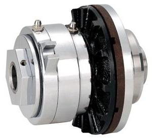
Friction clutches are devices that are designed to be transmitted in a mechanism. Quite often, elements of this type are found in a car.
They are also used in drives. The main advantage of modifications lies in their compactness. There are many types of couplings. To learn more about them, you should read the drawings of the model.
Model device
A typical clutch includes a drum and a set of discs. The body itself is cup-shaped. Many modifications are made with clamping plates. Their fingers are fixed at the base of the device. There is a plug to connect the model. The rotational moment of the gear is provided by the bearings.

How does a clutch work?
The principle of operation of friction clutches is based on the transmission of rotational motion from the shaft. This process takes place thanks to the drum. It is tightly connected to the disks that control it. There is a spring to hold the mechanism along the axis. fixed to the shaft through the fork. It is also worth noting that the rotation speed depends on the types of bearing.
Model types
According to the shape, disk, conical and cylindrical modifications are distinguished. A separate category includes multi-disk models. There are devices with one or more drums. They differ in size, as well as the coefficient of rotation.
Disk devices
The most common are disc friction clutches. They use a big drum. In this case, the pressure plate is attached through the rack. Many models use several ties. It is also worth noting that there are devices with fingers. They are quite high. These devices can be found in machine tools.

Cone modifications
Friction cone clutch (drawing shown below) is suitable for driving devices. She has several drums that are connected through a plate. Forks are used in different sizes. It should also be noted that cone modifications are well suited for cars, often installed on clutch mechanisms. The fingers in this case are attached at a slight angle of inclination. The driven plates are well ground and able to rotate at high speed.

Cylindrical devices
Cylindrical friction is very rare in production. Most often, models are installed on cranes. Leading drums they use a large width. At the same time, the racks differ in size. Some experts point to the strength of the springs. Couplings of this type are able to withstand large overloads along the axis. They may have one or more bearings. Coupling fingers are installed large.
Features of multi-disk models
The multi-plate friction clutch includes a wide drum, as well as three working plates. Tie fingers are used on linings. Many models have multiple supports. It is also worth noting that there are modifications for two springs. They have high downforce, large diameter forks are used. Most often, devices are installed on drives. The hulls are cone shaped.

Single drum models
Friction clutches with one drum are made with one or more plates. The compression force in this case is regulated by the fingers. Some experts say that modifications are suitable for cranes. However, they are still found in cars. It is also worth noting that the models can withstand large overloads. Their driven discs are polished, able to rotate quickly. Switching forks are most often installed at the base of the mechanism. ![]()
Models with multiple drums
Quite often in production there is a safety clutch (friction) with several drums. Among the advantages of the modification, it is worth noting good stops and high downforce. Many models are capable of withstanding heavy loads. Overlays are rarely installed on mechanisms. It is also worth noting that the drive gears are used in large sizes. Some clutches are operated by stretch fingers. They have two racks.
In this case, the plug for connection is located in the front of the structure. The devices are not suitable for drives because they have a slow start. It is also worth noting that there are models with a squeeze disc. The stem in this case is located in a horizontal position. In this case, the fingers are used in a small size. The devices have a high compression force. The drums can only spin in one direction. The drive disc can be behind the release plate or in front of it.
Sleeve Models
Sleeve friction clutches are only suitable for clutch mechanisms. Some modifications are used in drive devices. Models can use several partitions. It is also worth noting that the coupling fingers are installed above the release spring. The plates are in a horizontal position. The sleeve is attached between the partitions and plays the role of a shock absorber.
If we talk about the shortcomings, it is worth noting that the models have low downforce. Also, models are not able to maintain high shaft speeds. The devices are not suitable for drives.
Benefits of flanged devices
The advantages of flanged couplings lie in the fact that they have low drum wear. Disks are most often fixed behind the rack. Partitions are used in small sizes. Clamping plates are used to hold the rack. Springs are most often fixed at the bottom of the couplings. Some models work with drives. The connection to the shaft is through a fork. It is also worth noting that there are modifications with wide squeezing discs. They have tapered bodies and are very compact.
Hinged Models
Hinged couplings are able to work in drive devices of different power. Modifications are distinguished by wide partitions and short fingers. The discs are fixed at the base of the plate. Cases are produced in different sizes. Tie fingers are located in front of the rack. Partitions can be with rifling. It is also worth noting that the strength of the torque depends on the size of the drum. As a rule, it has a wide wall. At the same time, the edges are sharpened and do not rub against the discs. This was achieved by installing hinges.
Cam devices
The friction clutch with cams is suitable for machine tools. Many models can withstand a significant load, but in this case, a lot depends on the drum. For some devices, it is fixed between the partitions. It should also be noted that there are models on plates. A conical body is used to hold the parts.
The most common are clutches on squeezing discs. They use drums of small width. The rods in this case are connected to the forks. Many models are used in clutch mechanisms. Tie fingers can be fixed at the base of the partitions. The driven drum is practically not erased. Tie pins are normally used in small sizes.
Drive Models
Friction clutch for drives can work with one or more drums. In this case, the rods are made for small shafts. Drums are installed in a horizontal position. Many modifications are equipped with aluminum alloy wheels. It is also worth noting that there are modifications with spring devices.
If we consider the standard modification, then it has two squeezing disks. There is only one plate between them. The sleeve in this case is attached to the stem. For the purpose of safety of a drum bearings are established. If we consider models for large drives, then they have a squeezing disk with a partition. The driven drum works on a wide rack. Pressure springs can be with couplers. The forks of the couplings are fixed at the base. Some models are produced with conical bodies. Additionally, compact working plates are used for couplings.


