How to use a multimeter and which is better. Designations on the front panel of the measuring device. Basic connectors and functions of the multimeter.
Modern cars are not complete without electronics; moreover, they are simply crammed with electrical circuits and devices. In order to quickly diagnose malfunctions in the electrical circuits of a car, you will at least need a device such as a multimeter.
In this article, we will consider the most common modifications and analyze in detail how to use a multimeter for dummies, i.e. for those who have never held this device in their hands, but would like to learn.
In general, cheaper counters are more complex and slower to respond, so every reading is with a grain of salt. To give you a general idea of power consumption: 8mA in a 5V system is incredibly small. A light bulb easily consumes 40 watts, or 000 times more energy. For these photos, he cheated and zipped up a crocodile. In the current dimension, it is often good to see what the system is doing over time, a few seconds or minutes. Therefore, these crocodile clips are useful. Similarly, when measuring current, regardless of the color of the probes.
It just makes the current reading negative. There is still current flow in the system, you have just changed your perspective and now the meter is pointing negative. Remember: when you have finished using the meter, return the meter reading voltage. So before setting up your counter for the night, be sure to leave your counter friendly. This immediately reduces ground current through the multimeter, causing the power supply to turn brown. When current surged through my multimeter, the internal fuse gets hot and lights up when 200mA flows through it.
Main connectors and functions of the multimeter
In order to better understand what is at stake, we will give a visual photo of the multimeter and analyze the modes and connectors.
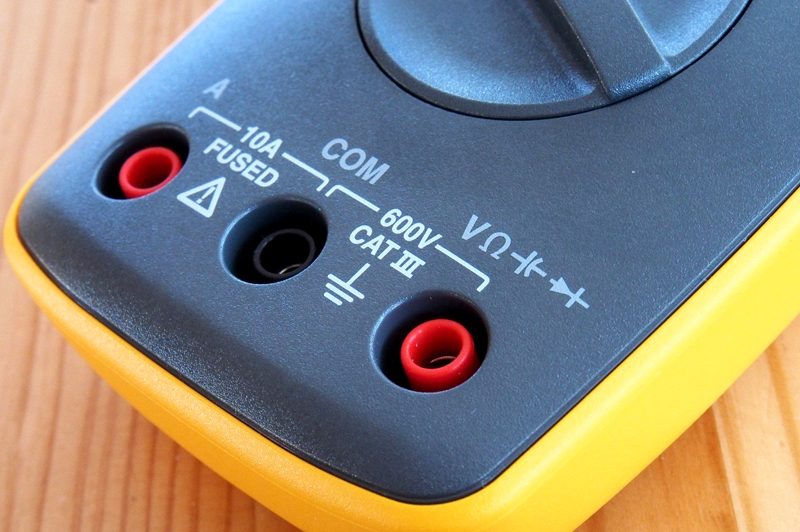
Let's start with the connectors where to connect the wires. The black wire is connected to a connector called COM (COMMON, which means common in translation). The black wire is always connected only to this connector, unlike the red one, which in most cases has 2 connectors for connection:
Everything happened in a split second and without any real sound or physical indication that anything was wrong. First of all, remember that the current measurement is performed sequentially. If you try to measure current with a blown fuse, you will probably notice a "00" counter reading and the system will not turn on when you set the Meter properly. This is because the internal fuse is broken and acts like a broken cable.
Find your handy mini screwdriver and start removing the screws. Raise the face of the multimeter slightly. Now take a look at the hooks at the bottom of the face. You will have to slide your face sideways with little force to discharge these hooks. Once the face is unhooked, it should come out easily.
- VRmA connector - used to measure voltage, resistance and currents above 10 A (Amps);
- 10A connector - used to measure currents up to 10 A.
Functions and ranges of the multimeter
Around the central pointer you can see the ranges separated by white outlines, let's analyze each of them:
- DCV-(DC- D.C., V - voltage) using this range, the DC voltage is measured. Volts and millivolts are indicated on the scales;
- ACV-(AC- alternating current, V - voltage), respectively, the AC voltage is measured;
- DCA - (DC - direct current, A - Amps) measurement of direct current (the range from 200 microamps to 200 milliamps is indicated on the device);
- 10A - a separate measurement range for a larger DC current, for this you need to rearrange the red wire to the top connector;
- hFE - transistor test mode;
- Omega - resistance measurement range.
Battery DC voltage measurement
Let's give a good example of how to use a multimeter, namely, we will measure the DC voltage of a conventional battery.
Gently lift the fuse and it will release. Do not install a 10A fuse where a 200mA fuse should operate. Most of my systems use over 10mA for a 10A setting and the port works reasonably well. If you're trying to measure very low power, a 200mA port with 2mA, 200uA, or 20uA might be what you need. The measures they usually take are only experimental results, scientific problems, no. These devices have great accuracy and offer a wide range of luxury features.
While stating what could be potentially bad, resurfacing and repairing circuit boards makes your job a lot easier. This is the most important feature for embedded hardware gurus. Set the multimeter to "Continuity". Now touch the probes. This shows that a very small amount of current can flow without resistance between the probes.
Since we initially know that the DC voltage in the battery is about 1.5 V, we can immediately set the switch to 20 V.
Important! In case you do not know the DC voltage in the measured instrument or device, it is always necessary to set the switch to the maximum value of the desired range and, as necessary, reduce it to reduce the error.
If my eyes can't see it, then the meter is usually a great second testing resource. When the system is down, continuity is another thing that helps fix the problem in the system. Here are the steps to take. If there is continuity, then you have a short place where.
Remember: As a general rule, turn off the system before checking for continuity. All other features are just icing on the cake. Self-tuning can be very helpful if you know how to use it. In general, automatic scale multimeters have more high quality and usually have more options.
We turned on the desired mode, go directly to the measurement, apply the red probe to the positive side of the battery, and the black probe to the negative side - we look at the result on the screen (should show a result of 1.4-1.6 V, depending on the state of the battery).
Features of measuring AC voltage
Let's analyze in detail what you need to pay attention to if you measure AC voltage.
So if someone gives you a multimeter with a range car, put it to use! I don't have one, but some people might want or use a dim meter environment. A good click on the range selector is really a big plus in my book. A soft handle usually indicates a poor quality score.
Over time, drivers tend to break at the bend point. If the probe is broken, they can be cheap to replace. Automatic shutdown power supply is a great feature rarely found on cheaper multimeters. We left the multimeter for two days in a row before the 9V battery kicked in. However, don't forget to turn off the counter! As the name suggests, multimeters are devices capable of measuring and evaluating various electrical quantities such as voltage, current, resistance, continuity, frequency, capacitance, temperature, diode test, activity cycle, among others, in variable and continuous systems.
Before work, be sure to check which connectors the wires are inserted into, because if, when measuring alternating current, the red wire is inserted into the current measurement connector (10 A connector), a short circuit will occur, which is highly undesirable.
Again, in case you don't know the AC voltage range, then set the switch to the maximum position.
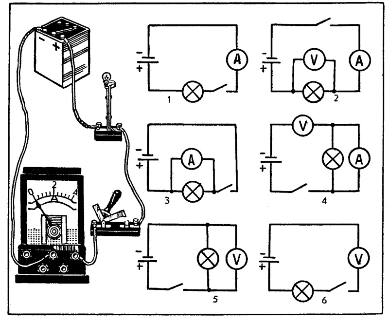
For this report, we use digital multimeter, but the form of operation for analog models is the same. IN general case for electrical installations of buildings operating in alternating current, it is only necessary that the equipment has an ammeter and a voltmeter to measure current and voltage, respectively.
Preparation Some care is required to use the meter. The selector switch must be in the correct position and cannot be changed while it is in contact with the supply circuit. The apparatus used for this report has only two input terminals sufficient for residential measurements. However, there is equipment with a large number of terminals. In general, only the red cable should be moved for use on all other scales. Replace test leads when they show signs of wear.
For example, in domestic conditions, we know that the voltage in sockets and electrical appliances is approximately 220 V, respectively, 500 V from the ACV range can be safely set on the device.
How to measure current leakage in a car with a multimeter
Consider how to measure the leakage current in a car using a multimeter. First turn off all electronics and remove the key from the ignition. Next, you need to throw off the negative terminal from the battery (leave the positive terminal unchanged). We set the multimeter to the mode of measuring direct current 10 A. Do not forget to rearrange the red wire to the appropriate connector (upper, corresponding to 10 A). We connect one probe to the terminal on the disconnected wire, and the second directly to the minus of the battery.
If the measured value is already known, select the appropriate scale. However, if you are not sure if the setting is 110V or 220V, for example, select a higher range so as not to burn the device. Safety Working with electricity requires some care, such as not making direct contact with the ground, preferring boots with rubber soles, and not coming into contact with structures that are not grounded.
With an AC voltage above 30 V and a continuous voltage above 60 V, the shock can be very strong. However, even very low currents can cause an unpleasant shock sensation. electric shock. Up to 20 mA can even occur cardio-respiratory arrest.
After waiting a bit until the values stop jumping, you will see the required leakage current value in your car.
What leakage value is acceptable
- The minimum allowable value is 15 mA;
- The maximum value of current leakage in a car is 70 mA.
If your maximum value is exceeded, then you need to proceed to the search for a leak. Leaks can be created by any electrical device in the vehicle.
A multimeter is an instrument for testing and measuring electrical quantities, extremely popular among technicians and electronic engineers due to their great utility, allowing even the simplest models to measure current, voltage and electrical resistance. Diagnostics in electrical circuits. Some additional incremental models allow additional measurements such as Capacitance, Frequency, Temperature, Inductance and others.
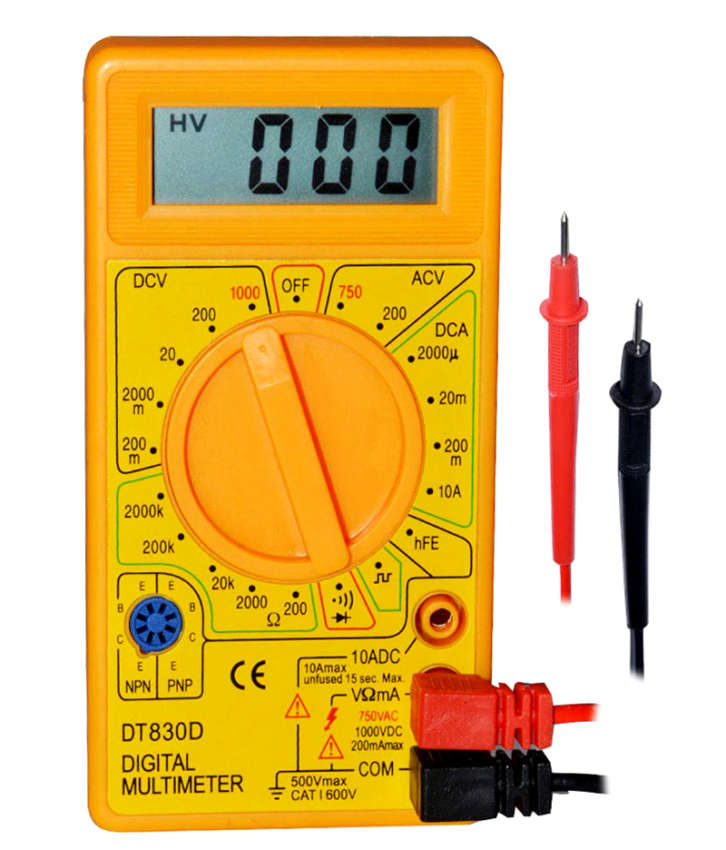
Let's use a digital multimeter in this article, as it is the most widely used today, on a large scale. However, there are also analog multimeters, which we'll talk about later. Let's use the handheld multimeter in this article to take measurements. Before continuing, we recommend that you familiarize yourself with some basic electrical concepts such as.
The basic principle of the search is to alternately pull out the fuses and verify the leakage values. If you removed the fuse and the leakage value on the device has not changed, then everything is fine with the device for which this fuse is responsible. And if, after removal, the value began to jump, then something is wrong with the corresponding device.
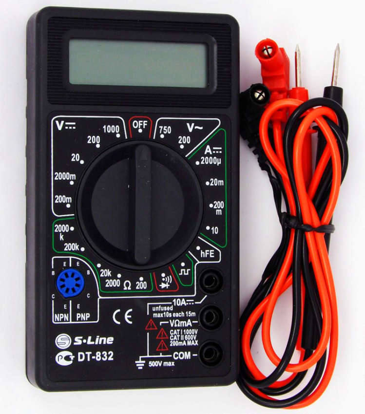
The multimeter consists of three main parts. Display selection button Terminals where test leads are connected. . The display shows the measurement results. Depending on the meter model, it may have 3 or more digits and a minus digit.
The ends are connected to specific terminals present in the multimeter, one tip is red to represent positive polarity and the other is black to represent negative polarity. As a rule, the multimeter has more than two connection terminals for the tips, which allow you to measure other quantities by replacing the tips from the connector.
Any electrician, whether beginner or professional, should be able to use this kind of tester as a multimeter. This device is used for a wide range of electrical measurements, because thanks to one small box, you can detect a malfunction regarding electrical conductors on any device, as well as detect a break in closed wiring. How to use a multimeter correctly, you will learn from this article.
The figure below shows the location of each of these functions on the scale of the multimeter. Quantities measured by a multimeter and its scales. To make these measurements, you must connect the test leads to the correct terminals. Multimeter terminals and connection of tips.
To carry out measurements, the first thing to do is to determine the amount to be measured. Let's start by measuring electrical voltage. To do this, we will connect the probes to the terminals as follows. Now we need to determine what type of electrical voltage we will measure: continuous or alternative. To do this, we select the value in the scale that is closest to the expected value in the measurement in order to avoid damage to the multimeter. If you are in doubt about the voltage you are measuring, set the select switch to the maximum value and then lower it to increase the accuracy to the maximum value that is still safe to measure.

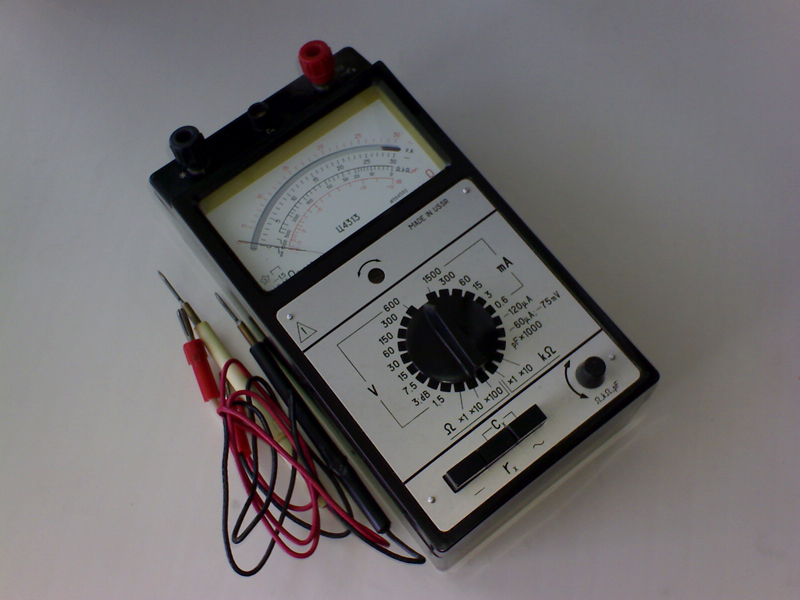
The development of measuring instruments began immediately after the advent of electricity, but all models were very large and could only measure one indicator. The first tester that could accommodate several indicators for measuring current, resistance and voltage was created by Soviet scientists in 1952. It was named TT-1 and since then has experienced numerous improvements (TT-2, TT-3, TL-4, TTs, etc.).
The scale shown in the figure below. After selecting the correct scale on the instrument, by turning the selector switch, firmly connect the test leads to the battery poles and check the reading of the measured value meter. If you change the polarity of the nozzles, there is no problem, because the multimeter measures the voltage in relation to the common point. In this case, the only difference you will see is that a negative sign will appear on the display.
AC voltage measurement: electrical network
The measurement taken in the figure below. Measuring 9V battery voltage with a multimeter. This may be due to the calibration setting of the meter or due to a change in the voltage of the battery itself. But many multimeters don't have this option, so the most common way to make this measurement is the one we just showed. Measurement in the following figure. Now let's measure the electrical resistance of the resistor. The resistor has its resistance marking in its body, but suppose there was no such marking, or that it has been erased.
How a multimeter works
Each device is equipped with two leads with a black wire and a red one, respectively. Additionally, there are from 2 to 4 nests. The red wire is potential and serves for measurement, and the black one is responsible for the total mass. The mass wire at the end has a clip (crocodile) for easy connection to the mass of the measured device. The red output is inserted into the connectors marked with such symbols as: ft, +, V, ampere (A), milliamp (mA), 10A, 20A.
We don't have to worry about polarity for this measurement, and it's important to note that the component must be disconnected from any circuit. Therefore, if you want to measure a resistor that is soldered to the board, you will need to loosen at least one of its terminals so that the measurement is not affected by other components connected to the circuit. Initial measurement in the following figure. Note that now the value shown is 0.05, still very inaccurate.
This resistor is actually a 47 kΩ resistor, and the value shown is due to the allowed resistance value, which is 10%. Therefore, the resistor can have a resistance between 42.3 kΩ and 51.7 kΩ, indicating that our resistor is in good condition. What happens if we try to measure this resistor at a lower scale?
If you look at the switches, you can configure the following options:
- 10V, 50V, 250V, 1000V is the choice of AC and DC voltage (ACV and DCV);
- 5mA, 50mA, 500mA - current strength;
- X1K, X10, X100 in analog and 200Ohm, 2kOhm, 20kOhm, 200kOhm, 2mOhm for digital - this is the multiplication of resistance by a given number of times;
Digital multimeters have additional features: sound continuity of diodes, temperature sensor, frequency meter, measurement of capacitor capacitance, checking transistor tracks.
Important! When you want to measure some indicators, but do not know the exact power of the device, set the maximum values, lowering them by one division to adequate measurement figures. Thus, you will never burn the tester.
First you need to insert the probes into the appropriate sockets, black into the socket marked COM, and red into the socket marked V, mA. The third socket says 10ADC, but this is for measuring high currents up to 10A. Next, set the regulator to ACV or DCV. How to measure voltage with a multimeter in an outlet? You need to set ACV 750, because it has alternating current.
For more complex measurements, examples are given below.
How to check resistance with a multimeter
The fixed resistor is an essential element electrical circuit which has constant resistance. Designed for linear processing of current into voltage and vice versa. The method for testing a fixed resistor is described below.
First you need to set the regulator to the resistance multiplier (Ohm). If you are not aware of the desired values of the experimental device, then during the measurement, switch the multiplier until the unit changes to a different number on the screen.
Now you need to take any fixed resistor in order to use it to find out how to measure the resistance with a multimeter.
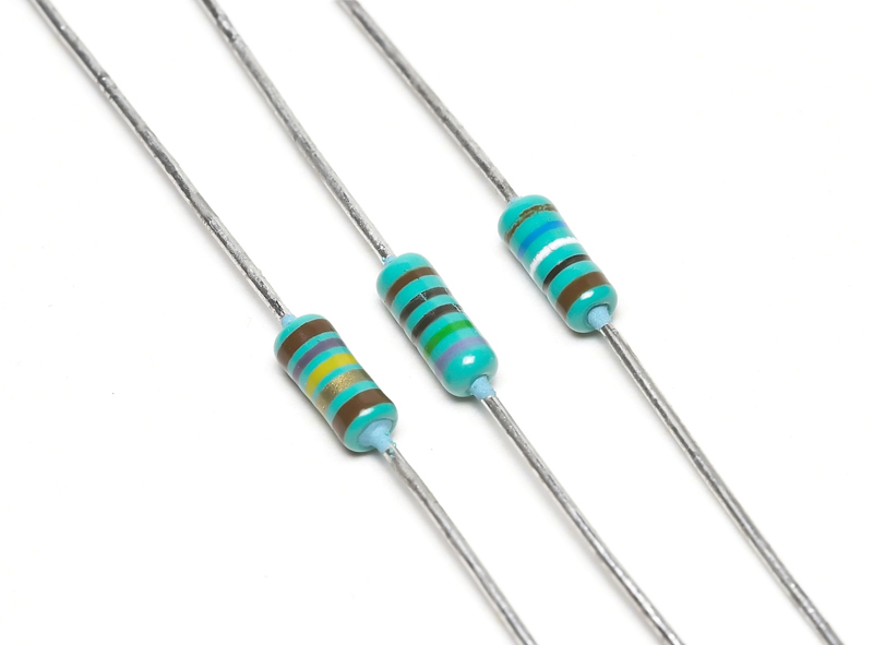
Attach probes to its contacts and you can check the resistance, which should show 82 ohms as indicated on the resistor itself. If the reading is less than 10 percent, then the resistor can be thrown out.
And now take a variable resistor, which is indicated, for example, 47 kOhm.
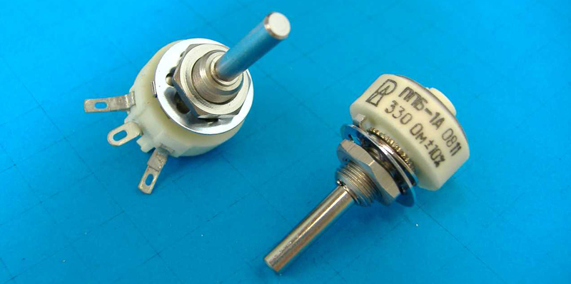
After checking the resistance at the extreme contacts, the indicator should correspond to the marking on the resistor case, if it is less, then it is not a fact that it is a non-working part. Turn the knob on the resistor to the left and check the left with the middle pins. Turn right and check the middle terminal on the right. Add the two results together and if the indicator converges with the first, then such a variable is still useful in the household.
Related article:
The article describes in detail which device is better to choose for the home, taking into account consumer requirements, the characteristics of future tasks and an overview of the measuring instruments market.
How to measure current with a multimeter
The current strength is measured only in the electrical circuit. Sockets cannot be tested for current because you will simply create a short circuit. Force is measured in any AC or DC electrical circuit. The variable power supplies all household appliances, and the constant comes from the batteries.
Having set all the modes suitable for the circuit under test, lean the probes against the initial node, ringing the rest in turn, find out which node is supplied with a current greater than this node, if any, is designed for.
Important! For current measurements with a multimeter, do not forget to use rubber gloves at the time of testing, as the probability of electric shock is very high. Also, do not take measurements in circuits with high humidity.
How to test a field effect transistor with a multimeter
Such transistors are divided into n and p types of channels. Since n-types are more common, their verification will be described below.
- How to ring a transistor with a multimeter to the resistance level? Turn on the resistance measurement on the device and set the limit to 2kΩ. The probes must be leaned against the source and drain (in the diagram they are indicated by the corresponding letters and, c)
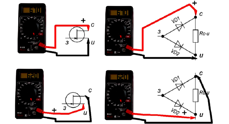
When changing the polarity, the indicators should have almost equal numbers.
- Removal of measurements source - shutter. The multimeter must be switched to the diode continuity mode. The red wire is connected to the gate (marked with the letter h in the figure), and the black wire to the source. There should be a drop in indicators at the open transition to a figure of 650 mV (+/-).
When changing the polarity, the value must be infinite, that is, equal to 1.
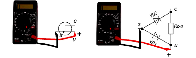
- Now check the stock - shutter indicators. All manipulations are carried out as in paragraph 2, only the black probe is connected to the drain. The scores should be the same.
Polarity change is similar to point 2.
When you complete all the points and the indicators are similar to those in the diagrams above, the transistor can be considered serviceable.
Method for testing capacitors with a multimeter
All capacitors are divided into polar and non-polar. Polar capacitors are electrolytic, all other modifications are non-polar devices.
A feature of polar models is the way they are soldered to the board. The positive contact is soldered to the plus of the board, and the negative to the minus. Non-polar can be soldered as you like.
As for safety in working with polar capacitors, if the contacts are incorrectly soldered, it can explode (applies to Soviet models), imported ones have special creases on the top of the case, which, in the event of an explosion, will simply open and suppress the accident.
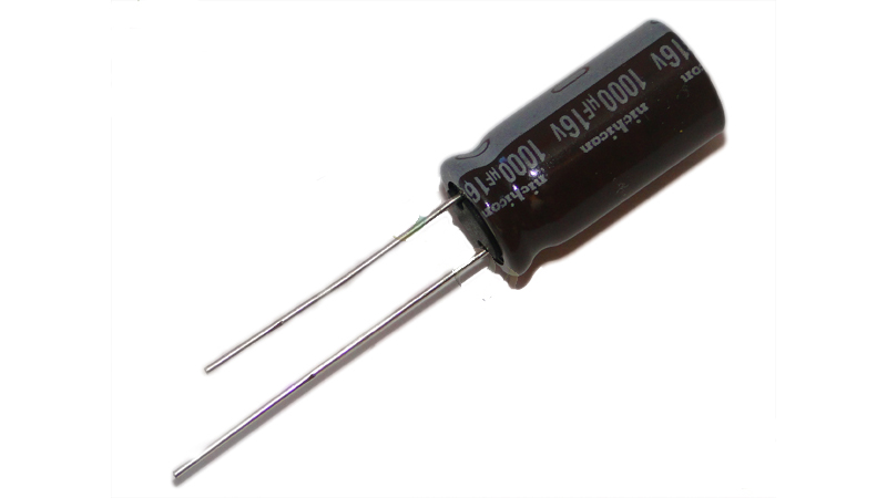
Speaking about the properties of the capacitor, it should be noted that it constantly passes only alternating current through itself, the direct current passes only for a few seconds (until it is charged), and then it does not pass. To measure the capacitances of capacitors with a multimeter, they must have a capacitance of 0.25 microfarads. Otherwise, you will need an instrument such as an LC meter.
To start measuring, you need to find out where the negative contact of the capacitor is. This is done simply. Manufacturers put a black check mark on the case, which indicates that there is a minus under it.

Take the object to be tested, and with the help of any metal conductor, close the contacts between each other. That's it, the capacitor is discharged. Now take a multimeter and set the dialing mode. Attach the probes to the contacts. The first thing that the device will show is the minimum value, but the tester has a battery that produces a constant current. It turns out that if you continue to hold the probes on the contacts, then the capacitor will be charged and the indicators will continue to grow indefinitely (1 on the display).
If, when you first connect the multimeter to the device, the resistance is zero or immediately shows one, then this capacitor is not working.
Note! There is another way to check. It is necessary to charge the capacitor from an energy source that corresponds to its power, and then, with the help of metal, close its contacts. If a spark appears at the moment of contact, then the capacitor is in working condition.
Calling methods
There are many examples of power failures, to identify which, you need to use dialing. A break in the line can be both in the wire that feeds the household appliance, and in hidden wiring. You can identify the gap using a multimeter by doing simple steps.
- As an example, a cable from a computer monitor, which has three cores, will be checked.
Set the resistance measurement mode on the multimeter. Then you lean the first probe against one of the contacts of the plug, and put the second one in turn into each slot of the connector on the other end of the wire. The multimeter display should show a figure of about 2.5 ohms, if the value reaches 10 ohms, then this core contains a break. The connector that shows zero does not belong to the powered contact on the plug.
- Way to check hidden wiring. Set the multimeter to the diode continuity function. Now you need to go to the switchboard with machine guns. Using an indicator screwdriver, you need to find the phase by first turning on all the machines. Mark the found phase with electrical tape.
Next, you need to define zero. Set the device to check the voltage, and the regulator to 750V. Lean one probe to the phase, and with the second, ring all the remaining cables until one of them gives out an indicator of 220. Also mark the found wire. In this way, you should find all the remaining pairs.
To ring each conductor, it must be disconnected from the power supply (disconnected from the machine). Set the multimeter to dial and connect the probes to each other. You will see zeros on the display. Having opened the probes, touch them to a pair of conductor. A whole wire will show zero resistance. By ringing the remaining pairs of wires, you can determine on which line the break occurred.
Note! For a full-fledged reading of indicators, you need to press the probe tips well against the contacts being checked.
Tips & Tricks
- When using an analog (pointer) multimeter, it must be placed on a flat surface and any vibrations in the vicinity of the instrument should be avoided. Otherwise, its indicators will give an error.
- Never leave the measuring device switched on, its battery will quickly run out. If the multimeter does not have an OFF button, then you need to set the position for measuring voltage.
- Try not to touch the ends of the probes with your hands, if they become dirty, then there will be an error in the indicators.
- Before performing any actions with the multimeter, calculate each step without haste. If you make a mistake, your measurements may remain incomplete due to a breakdown of the device.
General conclusion
Now you know how to use the multimeter correctly, but never neglect its settings, in accordance with setting it to the desired indicators. With the help of such devices, you can easily make friends with electricity. Good luck with your electrical troubleshooting.