Column base plates. Types, designs of column bases and their calculation
The allowable stresses for steel are much greater than the allowable stresses for concrete. Therefore, efforts in steel columns, having relatively small sections, should be distributed over such an area that the stress under the column does not exceed that allowed on the reinforced concrete foundation. To do this, the columns have steel base plates.
When substations and substations are installed where the ambient air may contain materials that degrade the insulation or disintegrating equipment and fuse, it must be used for the reliable operation of the equipment: reinforced insulation; shafts are made of environmentally resistant material or painted protective coating; Distributors and substations installed in the prevailing wind direction; Distributors and substations are located according to the simplest schemes; closed switchgear and substations are protected from dust, harmful gases or vapors entering the premises.
1. Concrete compression under the steel base plate, negligible at the edges, increases to a maximum under the column (a). In the calculation, the distribution of pressure on the concrete under the base plate is assumed to be uniform (b).
2. Bending moments appear in the base plate. To perceive these moments, it must either be of sufficient thickness or have stiffeners.
Specially designed aluminum and steel aluminum wires for corrosion protection should be used when installing outdoor stations near seafood or chemical plants or in places where long-term operating experience has caused corrosion of aluminum.
Open switchgear should be equipped with heating circuits for gear shifting and other cabinets using indoor appliances or terminals in accordance with the manufacturer's instructions. Switches with a voltage of 6 kV and above must be equipped with a functional lock to prevent false alarms.
3. With rigid fixing, the column, in addition to the vertical load, also transmits a bending moment.
- a) The influence of the bending moment is small compared to the influence of the vertical force (stress under the slab of the same sign).
- b) With large bending moments, tensile forces appear at the edge of the slab, which must be absorbed by the appropriate anchoring.
5. After the final alignment of the column, the gap under the base plate should be densely filled with high-strength concrete. Once the concrete has hardened, the steel plates and wedges must be removed.
The earthing switches of the enclosed switchgear must be locked. Computer controlled software and ground switches are disabled. The network of circuits and electrical equipment and the combined partitions of open partitions and the level of the transformer of the level of the open transformer should be 2 m high or 1.6 m and 1.9 m high from the closed switchboard and inside the transformer floor. The lower edge of the partitions should be at a height of not more than 0.2 m in open partitions and at the level of closed floors.
6. A thick column base plate is less labor intensive than a ribbed design (fig. 8) and in most cases represents a more economical solution despite the higher steel consumption. Such a support has an insignificant structural height compared to the design in Fig. eight.
7. Pipe columns are also mounted on a thick base plate without ribs. Thin base plates must be reinforced with radially arranged stiffeners.
External partitions must be installed in accordance with the requirements of paragraph 55 of the Rules. Terminal inputs of terminals, transformers and other drum devices are used to test voltage components. Barriers should be installed at a height of 1.2 m and in such a way that they can be removed if necessary. If the floor of the chamber is more than 0.3m above ground level, leave a distance of at least 0.5m between the door and the barrier, or provide a viewing area in front of the door.
Distribution and substations must be equipped with means to prevent dangerous mechanical stress due to temperature changes, vibration, etc. in cables, cables or insulators. The oil level and temperature of oil-immersed transformers and appliances, as well as gaseous gas gauges and other indicators indicating the condition of the equipment, should be located in such a way that it is convenient and safe to monitor them without cutting off the voltage.
8. A simple solution for a column support made of an I-beam RV profile with a thin base plate and ribs reinforcing it. The stiffeners are attached to the shelves. With such a constructive solution, the consumption of steel, although less than in Fig. 6, but the support has a large structural height and is more laborious to manufacture.
9. Support of a powerful box-shaped column with a thin base plate reinforced with stiffeners.
Electric wires for protective, measuring, signal and lighting circuits, which must be laid on the surface of electrical equipment of oil installations, must be insulated with an oil-resistant material. Outdoor transformers, reactors and capacitors should be painted in light colors to minimize heating from direct sunlight. In addition, these paints must be oil and weather resistant.
Distribution and substations should be equipped with electric lighting. Lighting equipment must be installed in such a way that it is safe to operate. Distribution and substations must be equipped with control and signaling devices.
10 and 11. To transfer the horizontal forces from the column to the foundation, the frictional forces arising from the action of the load on the column are often sufficient. With large horizontal forces and small vertical loads (for example, due to the action of wind), dowel-type protrusions must be reinforced on the lower plane of the base plate, which are inserted into the corresponding recesses of the foundation. For this, for example, welded steel bars (Fig. 10) or sections of profiles (Fig. 11) are used.
Distributors and substations are installed in accordance with the provisions of the Law on Construction of the Republic of Lithuania. The distance between plots and trees above 4 m should be such that when passing through the trees the equipment and lanes are not damaged.
Acceptable levels in live and working environment. Artesian wells, wells for drinking water or plumbing should be installed in switchgears and substations where employees work constantly. Transformer substations must be equipped with a sanitary toilet.
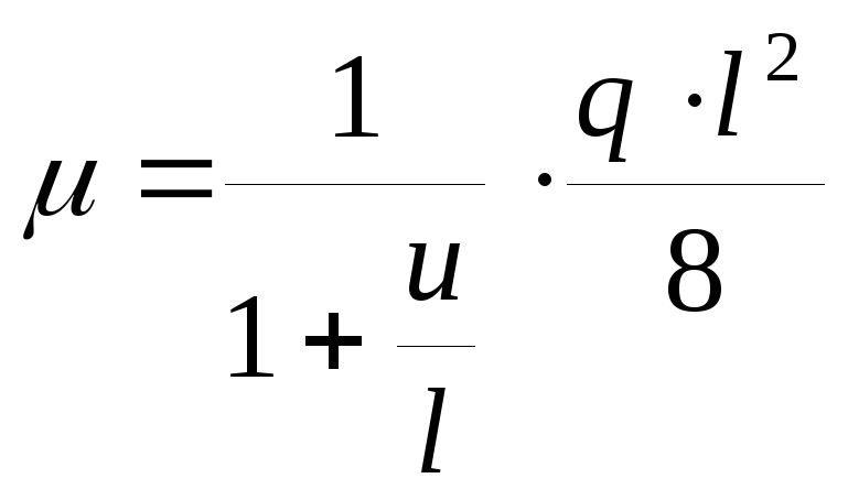
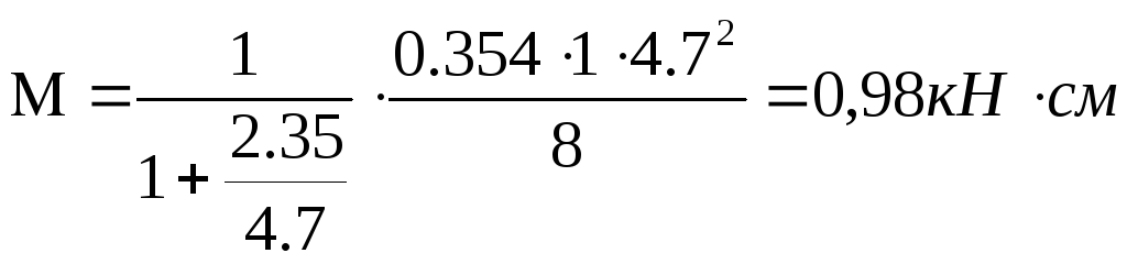
We count the base plate for bending, from the action of the crushing stress, as a single-span beam with two consoles.
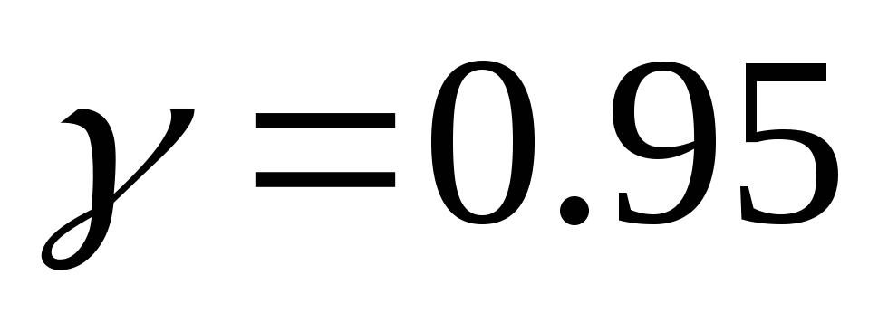
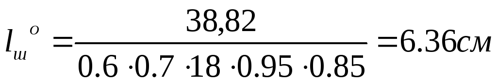
We take the size of the base plate 20 × 25 cm.
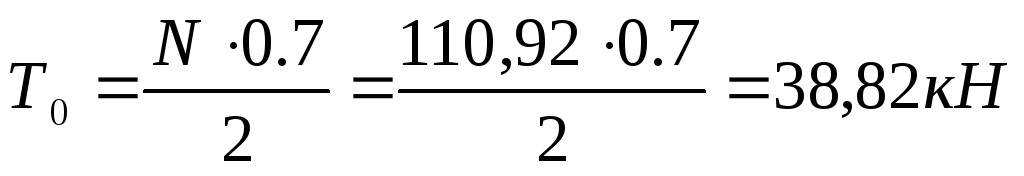
We accept that the base plate rests on a beam with  . The support reaction of the truss when it is loaded with snow over the entire span:
Enclosed transformer, modular and pole transformer housings are not required. Lids can be transparent or opaque. Technical requirements and test methods. Metal surfaces can be painted in addition to hot dip galvanized metal openings in large contamination control areas and the metalwork containing them.
In open distribution areas and subsoil areas where oil may leak from oil fields, oil storage facilities, machinery spaces, transformers and oil circuit breakers, oil collection and removal facilities should be installed to avoid contamination. environment.
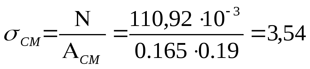
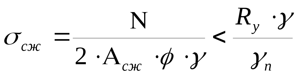
Collapse stress under base plate:
 <
<
The bending moment of the console is of greater importance than the bending moment in the middle of the slab.
To calculate a strip 1 cm wide:
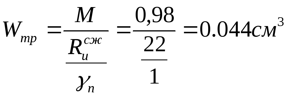
Moment of resistance:
Premises where sulfur hexafluoride is stored should be marked with a poster and their access to them should be limited. A number of installations, mechanisms and devices for repairs, as well as mobile laboratories, should be installed in open switchboards for 110 kV and above.
When calculating the loads of flexible shafts, it is necessary to evaluate the mass of conductors of insulators, as well as devices and transformers. When calculating structural loads, it is necessary to estimate the additional weight of a person and appliances and mounting fixtures: 200 kg for anchor supports and 150 kg for intermediate supports in garlands and 100 kg for support supports.

Required plate thickness:
We accept the thickness of the plate  →
→ , from the conditions of corrosion resistance and weldability (GOST 82-70).
The openings of open switchgear should not result in unacceptable mechanical stress at low temperature booms and should not allow the wire to come into contact with strong winds. The coefficient of elasticity of mechanical shocks of flexible shafts, when the loads comply with the requirements of paragraph 60 of the Regulations, must be at least 3 compared to their tensile strength.
The reserve strength of the rear insulators must be at least 4 in relation to the minimum insulator resistance when the loads comply with the requirements of paragraph 60 of the Regulation. The coefficient of elasticity of mechanical connecting equipment for flexible couplings, when the load complies with the requirements of paragraph 60 of the Rules, must be at least 3 in relation to the minimum resistance.
Calculation of welds for attaching girdle corners to vertical gussets in the support node.
The force on the seam at the butt of one corner:
Corner pen force:

We accept the leg of the seam  .
.
Exposed shield hangers should be made from prefabricated reinforced concrete, zinc, aluminium-zinc, or other strong steel structures. If intermediate supports are temporarily used as rear supports, they must be tightened. The number of suspension and support insulators and the external insulation of the electrical equipment of the switchgear are selected according to the voltage and environmental conditions.
The wind speed is estimated at 60 percent. calculations of building structures. With a three-phase short-circuit current of 20 kA or more and a cable deflection of 3 m or more in space, it is necessary to check the flexible openings of the switchgear for short-circuit currents that will be dynamically affected to prevent their convergence or dangerous phase. The loops must be installed in flexible posts, the phases of which consist of several wires.
Required seam length at the butt:

where  - calculated resistance of the weld metal. For accepted electrodes
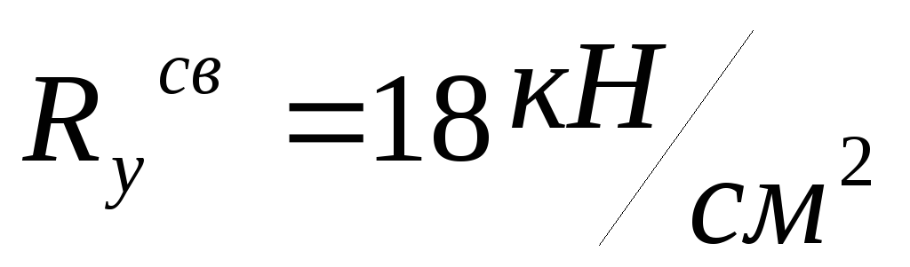
 - coefficient of penetration depth. When calculating for the weld metal
  .
.
In addition, the filter must be installed at a height so that it can be easily repaired. Transformers and devices with the lower edge of porcelain insulators at a height of at least 2.5 m above the surface or level of the equipment should not be fenced. When the height is less, the device must have a section that meets the requirements of paragraph 43 of the Rules, and is located at a distance from the transformers and apparatus specified in the Rules at point 70. The requirements for open-beam transformers to the building wall are set out in paragraph 81 of the Rules.
 - coefficient of operating conditions of the tensioned element.
 - coefficient taking into account the work of the seam.
Required feather stitch length:
The distance between the nearest unmatched flow paths of the various components must be chosen in accordance with the condition of maintaining one chain without disconnecting the other. If no work is provided under these conditions, the distances between different communication lines in different planes must be determined in accordance with the requirements of sections 67 and 68 of the Rules. It is also necessary to evaluate the potential connection of the wires. Here, the vertical distances from the conductors to the ground in the open distribution zone must not be lower than those specified in paragraphs 1 and 3 of the Rules.
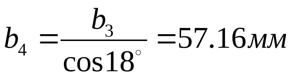
Structurally, we accept the length of the seam at the butt  , the length of the seam at the pen
  .
.
Calculation of welds for attaching a plate-rib of a thrust plate to vertical gussets.
We define the forces in one edge:
Lighting, communication and signaling lines should not line up above or below circuit breaker circuits. Distances from oil installations to explosive zones and premises are determined in accordance with the requirements of explosive zones of electrical equipment.
Distances from power plants and substations to open distribution of oil installations to closed housings of switchgears, panels, compressors are determined in accordance with technological requirements. The windows are installed only above the level of the transformer cover.

Required seam length:
Actual seam length:
>
Calculation of the intermediate node of the upper belt.
The node of the junction of the brace to the upper chord.
 Node structure. Nodal insert.
A path no longer than 3.5 m should be installed along the transformer yards. The requirements for article 81 of the Rules also apply to a complete transformer substation. Oils for oil transformers with specific oil over 1 ton and tank circuit breakers with voltages of 110 kV and above must be equipped with an oil plug, an oil drain and an oil manifold. When installing them, the following requirements must be observed.
The oil volume must be calculated for the total amount of transformer oil. The oil capacity of the tank circuit breaker should be 80%. one tank oil. Bone oil and oil drain channels should be installed so that oil can flow from one pit to another, channel leakage and other underground structures to prevent the spread of fire, oil pollution and clogging of channels, snow, ice, etc.

Vertical wall of metal liner  has the same height and width as the thrust plate and is calculated for bending as a three-span non-split beam under the action of shear stresses from the stop of the end of the upper chord.
In the absence of oil leakage, the oil pit should be calculated throughout the structure of the device covered with oil, and the metal network, along which should be distributed with a thickness of 0.25 m of clean washed gravel or stone or other non-cellular origin 30 to 70 mm layer of coarse sand .
A movable pump must be used to remove oil and water from the oil well. When oil wells do not have an oil drain, a simple oil control device is installed in the mine. The bottom of the oil pit must be below ground level or surface level. The height of the pit should be at least 0.25 m and not higher than 0.5 m above ground level. Holes with oil drain holes in the collector must be filled with at least 0.25 m of transparent gravel or washed stones or non-wood layers of other thicknesses from 30 to 70 mm.
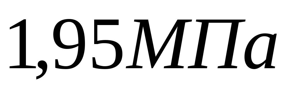
Collapse stress of the end of the upper chord:
 MPa
MPa  MPa
MPa
The bending moment of the plate - liner with a width of 10 mm (calculated strip) is determined by the formula in accordance with clause 5.22 of SNiP II-23-81:
where  is the bending moment at the end span, calculated as in
freely supported single-span beam;
L is the distance between the ribs of the insert, l=47mm=4.7cm;
 mm - distance from the section in which the moment acts
  to the extreme support.
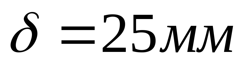
Required wall thickness:

We accept the wall thickness of the liner  .
.
Determine the diameter of the nodal bolt.
2) Nodal bolt, bending:
where
 -
plate rib thickness - insert;
-
plate rib thickness - insert;
 -
the thickness of the plate - the tip of the brace, we accept
-
the thickness of the plate - the tip of the brace, we accept  ;
;
D - effort in the brace,  ;
;
Definition of W tr.

Required bolt diameter:
 (because
 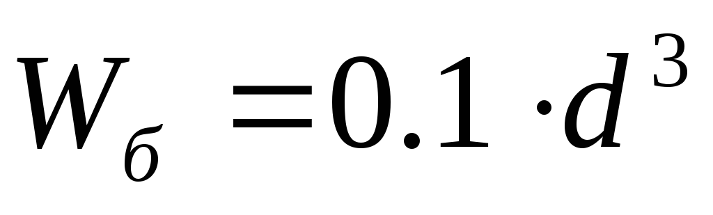 )
)
 cm
cm
We accept a knot bolt  (Grin, appendix on page 40),
  ,
,
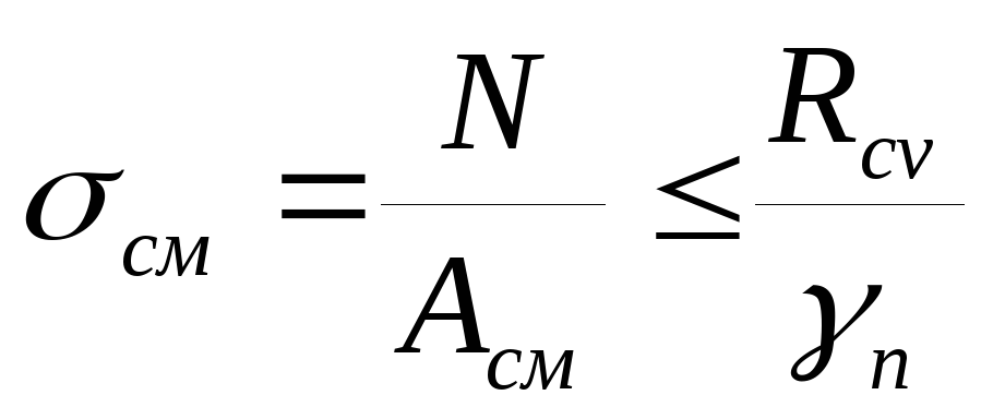
Bolt collapse stress:
where, 
Bolt shear stress:
 (v. 58 SNiP II - 23 - 81)
Calculation of plates - tips.
 3) The braces are connected to the upper and lower belt with metal plates - tips with a section
  .Metal plates work for longitudinal bending at a length equal to the distance from the center of the nodal bolt to the stop of the wooden part of the brace.
Free length of plates - tips  .
.
Flexibility of plates - tips:

 - compressed rods of steel trusses (p. 222, Belenya)
Buckling coefficient (vol. 72 SNiP II - 23 - 81, or Belenya, p. 534, appendix 7) for steel with design compressive strength  ,
,
Compressive stress in plates - tips:
where A szh - cross-sectional area of the plate - tip
 - coefficient of the working conditions of the compressed truss elements for
  (according to SNiPII-23-81, clause 6)
 for compressed truss elements (according to SNiP II-23-81, clause 6)
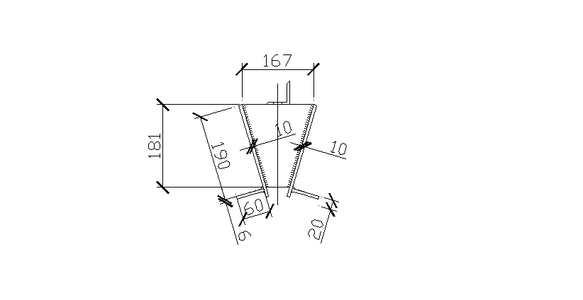
We count the plate against which the wooden brace rests for transverse bending approximately as a simple beam with a T-shaped section, as well as in the thrust plate of the support unit.
In this case:

Static moment of the cross section about the x-axis 1
Distance from the x-axis 1 to the center of gravity of the calculated tee section:
Moment of inertia about the X axis, passing through the center of gravity of the section;
Cross section moment:

Brace end collapse stress:
- crush area
R cm \u003d 9.75 MPa is the calculated resistance to crushing along the fibers.
Bending moment:
where l=150mm - calculated span of the plate, equal to the distance between the plates - tips in the axes;
 - slab width
Bending stress:
4) Determination of the t plate of the nodal insert.
The force component of the brace, perpendicular to the upper chord, is perceived by the emphasis on the upper chord of the lower plate of the nodal insert.
Stressed collapse across the fibers of the upper belt under the liner plate:
where, h pl - the height of the plate;
h 3 - the size of the gap;
R cm90 - design resistance to crushing in the supporting parts of the structure and nodal junctions of elements, for pine and spruce wood R cm90 \u003d 3 MPa (v. 1, Grin or v. 3 SNiP II-25-80);

Bending moment in the console of the lower plate from the calculated strip with a width of b=10mm:
Required moment of resistance:

Required plate thickness:

where b is the width of the design band; b=1 cm.
Accept plate thickness = 10mm.
The ridge knot of the truss can be solved with the help of a steel fastening, consisting of two gussets and a triangular diaphragm, bolts. The compressed rods of the upper belt are fastened with straight frontal stops and bolts to the inclined surfaces of the diaphragm, and the extended rod of the middle rack is fastened with a nut to the horizontal surface of the diaphragm.
a) Calculation of the metal wall-liner.
A metal insert is installed in the ridge assembly between the ends of the panels of the upper belt.
Collapse of the end of the upper belt:

 - calculated resistance to crushing along the fibers of an element of a constant height section of a rectangular shape, made of Weymouth pine.
We expect the metal wall of the insert to bend like a cantilever beam under the action of shear stresses from the stop of the end of the upper chord.
The bending moment of the cantilever part of the liner wall at the width of the design strip with a width of  .
.
where 
Moment in the middle:

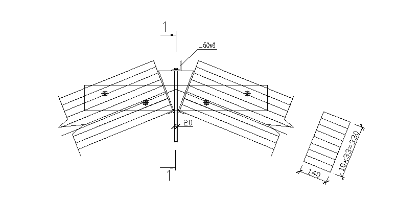

Required moment of resistance:

Required liner wall thickness:
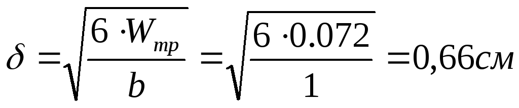
Accept 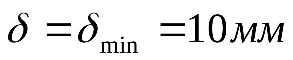 .
.
b) Calculation of the corner - washers of the rack:
Corner - rack washer count on bending:

where  - the distance between the ribs of the liner.
Required moment of resistance:

Accept  ,
,
Moment of resistance:

 - distance from the edge of the corner to the neutral axis;
![]() - corner height
- corner height  ;
;
 - distance to the center of gravity,
  ;
;
 - radius of gyration of the corner,
 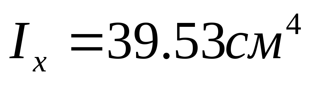 .
.