Support nodes of crane beams and joints of steel columns. Joints of beams and columns
Joints and details of columns
The joints of the columns are factory and assembly. Factory joints are arranged due to the limited length of rolled profiles (see section). Mounting joints are arranged due to limited transport capabilities (9 - 13 m when transported on one platform and 19 - 27 mm when transported on a coupler).
Factory joints of elements are usually spaced apart, not concentrating them in one place, since the connection of individual elements can be made before the general assembly of the rod. Examples of welded factory joints of individual elements of the columns are shown in the figure.
Factory welded joints: a - welded I-beam belts; b - I-beam branches
solid column; c - branches of a through column on the slats.
The main condition for the formation of a strong joint is to ensure the transfer of force from one element to another. When butt welding, this is ensured by the appropriate length of the welds (see section), and when butting with overlays, in addition to the required length of the welds, also by the corresponding cross-sectional area of the overlays, which should not be less than the cross-sectional area of the main joined elements.
The simplest and therefore the most recommended is a straight butt weld. The implementation of such a joint is possible in all cases, since in eccentrically compressed columns one can always find a section with reduced tensile stresses.
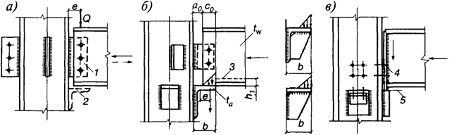
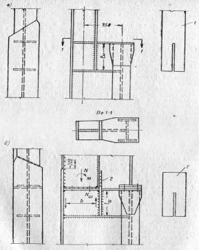
The mounting joints of the columns are located in places convenient for the installation of structures. For columns of variable section, such a place is a ledge at the level of support crane beams, where the section of the column changes.

The figure shows the types of joints of the upper and lower parts of a single-walled solid column: factory and assembly.
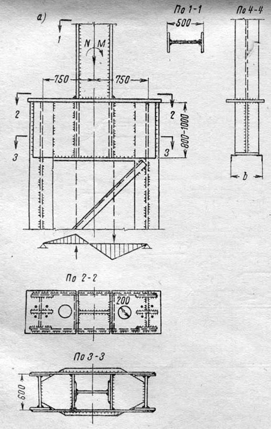
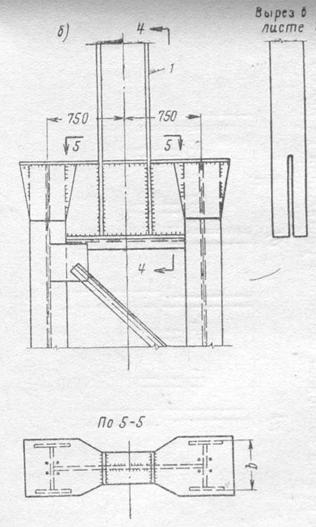
Attaching the over-crane part of the column to the through crane part.
The figure shows the attachment of the upper part of the column to the bottom through using a double-walled and single-walled traverse.
The length of the seams (l w in the figure above) required to attach the inner chord of the upper part of the column is determined from the condition that the moment M and the longitudinal force N acting in the upper part of the column at the place of its attachment to the lower part are perceived by the welds attaching the chords of the upper parts of the column; in this case, the seams attaching the wall are usually not taken into account.
Force in the belt, equal to
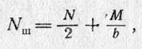
is transmitted through four seams that attach part 1 to the wall of the lower part of the column. Part 1 has a slot that allows you to fit it on the wall of the lower part of the column (the slot is made 2–3 mm larger than the sheet thickness). In the case of an assembly joint, this part is made separately from the girdle sheet, welding it to the bottom of the column.
In columns with a lower lattice part, the upper part is attached with a piece called a traverse. The traverse works in bending like a beam on two supports and must be checked for strength; the diagram of the moments in the traverse is shown in the figure. The attachment of the traverse to the branches of the column is carried out with continuous seams and is calculated on support reaction traverses. To ensure the overall rigidity of the junction of the upper and lower parts of the column, horizontal diaphragms or are placed.
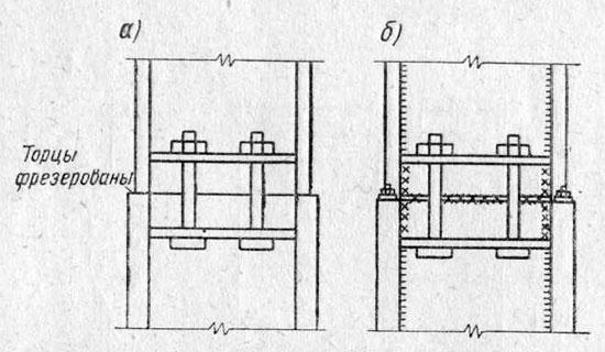
The assembly joint of columns of a solid section, which transmits predominantly compressive forces, can be made using milled ends. This type of joint is used in Moscow high-rise buildings.
In the case of transmission of the moment by the column, the welded joint shown in figure b is also possible, which does not require end milling. The arrangement here of a direct welded joint is possible provided that the equal strength of the welded and base metal is ensured.
It is usually assumed that in columns operating predominantly in compression, it is still possible for tension to appear at any end of the section. Therefore, at the joints, it is required to ensure the perception of a conditional tensile force, which is usually taken equal to 15% of the calculated normal compressive force (of course, if there are no real tensile forces that exceed this value).
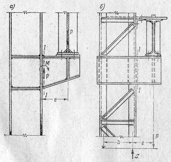
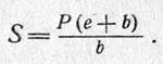
The support of crane beams on columns of constant section (in light workshops) is carried out by arranging a console from a welded I-beam (from sheets) or from two channels.
The console is calculated for the moment from the pressure of two adjacent cranes located on the crane beams: M = Pe, where e is the distance from the axis of the crane beam to the branch of the column.
The seams attaching the single-wall console are calculated for the action of the moment M and the shear force P.
The seams attaching the cantilever, consisting of two channels hugging the column, are calculated for the reaction S, found as in a single cantilever beam:
"Design steel structures»,
K.K. Mukhanov
Joints of multi-storey prefabricated frames, as a rule, perform hard. With hinged joints, the overall rigidity of the building decreases and the resistance to deformation under horizontal loads decreases.
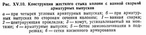
Rigid joints of columns of multi-storey frames perceive the longitudinal force N, the bending moment M and the transverse force Q. Reinforcing bars with a diameter of up to 40 mm are joined by bath welding (Fig. XV. 10). With four reinforcing outlets, for the convenience of welding, special corner trimming of concrete 150 mm long is arranged, while with reinforcing outlets along the perimeter of the section, concrete trimming is done around the entire perimeter. The ends of the columns, as well as the places where the concrete is cut, are reinforced with transverse grids and finished with a steel centering gasket (for ease of straightening during installation). After installation and alignment of the joined elements of the column and welding of the reinforcing outlets, additional mounting clamps with a diameter of 10-12 mm are installed. Joint cavities - concrete trimmings and a narrow seam between the ends of the elements are monolithic in an inventory form under pressure. Studies have shown sufficient strength and reliability of the joint. In comparison with other joints arranged for welding of steel embedded parts, the described joint is more economical in terms of steel consumption and labor intensity.
Reducing the bending moment at the joints of the columns of a multi-storey frame building in most cases is achieved by choosing the location of the joint closer to the middle of the floor height, where the bending moments from the action of vertical and horizontal loads approach zero and where the conditions for mounting the columns improve.
Joints are considered for 2 stages of work:
A) before the monolithic joint - on the loads acting at this stage of the construction of the building.
When determining the forces, such joints are conventionally assumed to be hinged.
B) after monolithing the joint - to the loads acting at this stage of the construction of the building
and during operation, when determining the forces, such joints are accepted as rigid.
The calculation of non-monolithic joints is carried out for local compression of the concrete column of the centering gasket.
The calculation of monolithic joints is carried out as for the section of the column in the section with undercuts, taking into account the following guidelines:
A) in the presence of indirect reinforcement with meshes both in the concrete of the column and in the concrete of the embedding, the calculation is carried out in accordance with the recommendations for the calculation of compressed reinforced concrete. elements reinforced with indirect reinforcement, while considering a solid section
B) In the presence of indirect reinforcement only in the concrete of the column, the calculation is carried out only taking into account indirect reinforcement, but without taking into account the concrete embedded, or vice versa.
2. Types and features of structures, and calculation of crossbars, beams, trusses
Prefabricated building structures, assembled from individual elements, work together under load due to joints and connections that ensure their reliable connection. Joints and connections of prefabricated structures can be classified according to a functional basis (depending on the purpose of the connected elements) and on a design basis (depending on the type of forces acting on them).
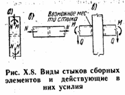
According to the functional feature, the joints of columns with foundations, columns with each other, crossbars with columns, support nodes of crane beams, trusses, roof beams on columns, support nodes of panels on crossbars, etc.
According to the design and construction feature, joints that are under compression are distinguished, for example, the joints of a column (Fig. X.8, a); joints in tension, for example, joints of a stretched truss belt (Fig. X.8, b); joints working in bending with a transverse force, for example, in the connection of a crossbar with a column (Fig. X.8, c), etc.
At the joints, the forces from one element to another are transmitted through the working reinforcement, which is connected by welding, metal embedded parts, monolithic concrete.
The dimensions of the gaps between the connected elements are assigned as small as possible. Their value is usually determined by the availability of welding of reinforcement outlets, the convenience of laying a concrete mixture in the joint cavity from the condition of repayment of manufacturing and installation tolerances; it can be 50-100 mm or more. When filling joints with mortar, especially under pressure, the gap may be minimal, but not less than 20 mm.
To prevent corrosion and ensure the necessary fire resistance of the elements, steel embedded parts are covered with a protective layer of cement mortar over a metal mesh.
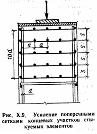
The end sections of the compressed connected elements (for example, the ends of prefabricated columns) are reinforced with transverse meshes of indirect reinforcement. When connecting with a break of the longitudinal working reinforcement in the joint area, reinforcement with transverse meshes is carried out according to the calculation. Grids are installed at the end of the element (at least 4 pieces) at a length of at least 10d rods of a periodic profile, while the grid spacing s must be at least 60 mm, not more than 7z the size of the smaller side of the section and not more than 150 mm (Fig. X. 9). The size of the grid cells must be at least 45 mm, not more than 1/4 of the smaller side of the section and not more than 100 mm.
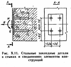
In joints and connections of precast concrete elements, steel embedded parts are often designed in the form of plates and anchors welded to them, experiencing the action of forces M, N, Q (Fig. X.11). To calculate the anchors, the bending moment is replaced by a pair of forces with a shoulder r and the forces are determined taking into account the experimental coefficients. The cross-sectional area of the anchors of the most stressed row:
The joints of the tensioned elements are performed by welding the outlets of the reinforcement or steel embedded parts, and in prestressed structures - by passing through the channels or grooves of the elements of the beams, ropes or rod reinforcement, followed by tension. Welded joints of tensioned elements are designed so that during the transfer of forces there is no extension of embedded parts, overlays or concrete punctures.
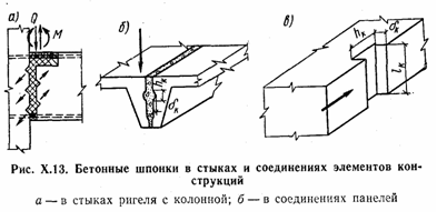
To transfer shear forces, grooves are arranged on the surface of the elements to be joined, which, after being monolithic, form concrete dowels. The use of concrete dowels is advisable in non-cantilever joints of crossbars with columns, where they are placed so that the concrete of the dowels works in an inclined section in compression, at the joints of slab structures, to increase the rigidity of panel ceilings in its plane, etc. (Fig. X.13).
4.6. Structures of frame elements
Columns. The columns of a multi-story frame structure are the main structural elements of the frame. They perceive and transmit to the foundation mainly vertical loads, but also participate in the perception of moments from wind loads. Within the floor, the section of the column works in compression, sometimes with a bend in one or two planes. Compared to the longitudinal force, the contribution of bending moments to the stress state of the column is usually small, so it is most often calculated on the central compression. Since the columns
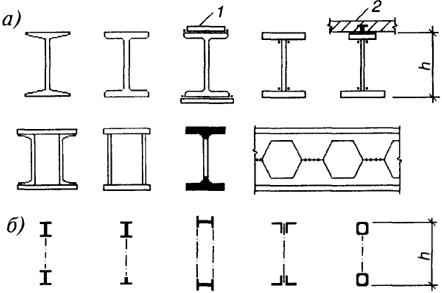
Rice. 4.20. Types of sections of columns of multi-storey buildings:
A- double-tee; b- closed; V- cross; G- hollow rolling; d- through
can lose stability in two directions, then the direction with less rigidity is calculated and, therefore, for columns, cross sections are more advantageous, the moments of inertia of which are the same about both axes. Profiles with significant differences in moments of inertia can only be used when their stability in a plane of lesser rigidity is ensured by pinching in the floor level or additional height fixings. Applied types of sections of columns are shown in fig. 4.20.
I-beam profiles(Fig. 4.20, A) is the most common sectional shape of columns in multi-storey buildings. It is especially convenient when it is necessary to attach floor beams to columns in two directions, since all elements of the I-beam are available for organizing support nodes. Depending on the acting forces, they are used as rolling I-beams with parallel edges of the modification shelves TO(column), and welded I-beams made of sheet steel up to 60 mm thick. The use of I-beam columns makes it possible to use their internal space for engineering communications (Fig. 4.21).
Rectangular box sections(Fig. 4.20, b) are used for high longitudinal forces and bending in both directions or for a large free length of a column with a limited cross section. The cross-sectional area in these profiles can be adjusted by changing the thickness of the sheet. Due to the even outer planes, it is possible to use such columns without cladding. For heavy loads, it is sometimes rational to use a solid square
Rice. 4.21. Examples of the location of utilities in the dimensions of the section of the columns:
a, b- I-section; V- through section
profile (slab), which has a high degree of fire resistance with small overall dimensions. The cross section of two twin channels is suitable only for relatively small loads.
Cross profiles(Fig. 4.20, V) due to the complete symmetry of the cross section, it is rational to use for columns in the presence of bending moments in them in both directions. Cross sections were used in the frame of the high-rise part of Moscow State University, which made it possible to solve the junction points of crossbars of different directions in the plan in the same way.
Hollow profiles(Fig. 4.20, G). Round pipes are advantageous from a design point of view, since they have the same moments of inertia in all directions. Pipes with the same external dimensions can take different loads by changing the wall thickness. Since the cost of pipes is 3 ... 5 times higher than the cost of rolled sheets and I-beams, their use in most cases turns out to be more expensive than columns made of box sections. The use of hollow rolled profiles can be effective when filled with concrete.
through columns in modern construction multi-storey buildings are practically not used, since they are less compact and more laborious to manufacture and install. However, they can be successfully used in the construction of the frame of a multi-storey building, if it is planned to lay engineering communications between the branches of the column (Fig. 4.21, V).
The thickness of sheets in composite sections is usually taken no more than 60 mm, and the ratio of the dimensions of the section to the calculated lengths h/l x, b/l y not less than 1/15, which corresponds to a flexibility of 40 ... 60 (depending on the type of section).
The ratio of the width and height of the section and its orientation in the plan should be chosen taking into account the working conditions and the layout of the entire structural system. For example, in a conventional frame system, the plane of greatest rigidity of I-columns is directed along the narrow side of the building; in a system with an external spatial frame, this plane is combined with the plane of the frame face.
The calculation of the columns is carried out according to general rules(see § 6.4 and clause 6.7.7), while the coefficients of effective length for columns of frame frames are determined by the formulas of table. A6.1, and for braced frames according to the formula
μ = √| 1 + 0,46(p+n) + 0,18pn |
| 1+ 0,93(p+n) + 0,71pn |
Column joints decide depending on the ratio between the magnitude of the normal force and the moment at the junction. If the eccentricity e = M/N does not exceed the sound distance p = W/A, then the joint is performed as for a centrally compressed column (see Fig. 6.56, b), as a rule, with preliminary milling of the ends. At the same time, mounting angles are installed only on the wall so as not to spoil the appearance of the column. Such a joint can also be used for small eccentricities exceeding the sound distance by checking the strength of the mounting brackets and their fastenings for tensile force from the moment. For large eccentricities, joints with overlays are used (see Fig. 6.56, V). The use of flanged joints is hampered by the need to hide the protrusions of the flanges in the column lining, in the wall or in the floor structure, but in the latter case, the joint is located in the immediate vicinity of the junction of the crossbar with the column, i.e. in a place with a large bending moment.
Column bases. In the frames of multi-storey buildings, as a rule, bases are used for the installation of columns without alignment (Fig. 4.22, A). The base slab (usually from slabs) with a milled or planed upper surface is installed on the foundation along the center axes, focusing on the risks 2 , align with set screws 3 and poured with cement mortar.
At relatively small bending moments, when the anchor bolts 4 do not work or experience small tensile forces,
Rice. 4.22. Column bases:
a- with structural anchor bolts; b, c- with calculated anchor bolts; 1
- milling plane; 2
- installation risk; 3
- mounting bolt; 4
- anchor bolt; 5
- washer; 6
- gravy
they are placed constructively and attached to the column through a rib or corner shorts.
Column bases with calculated anchor bolts (Fig. 4.22, b, c) are designed in accordance with the instructions of paragraph 6.8.5.
Beams and crossbars. Beams and beams of floors work mainly in bending. Longitudinal forces in crossbars and beams, as a rule, are insignificant and appear from horizontal loads transmitted through the beam from the outer wall to the diaphragm, the stiffening shaft, and from transverse forces in columns due to the initial fracture or curvature of their axis.
In multi-storey construction, beams are most often used (Fig. 4.23, A) with a solid wall with spans up to 12 m and are made of ordinary, wide-shelf or welded I-beams. Asymmetric welded I-beams are used, as a rule, in the case of including a reinforced concrete floor slab in joint work with a beam γ f= 1.0 (composite-reinforced concrete beams). Double-walled welded beams are used for high transverse forces, as well as when it is necessary to increase horizontal rigidity. When placing engineering systems within the height of the interfloor ceiling, it is advisable to use beams with a perforated wall (see clause 5.9), which are obtained from wide-shelf I-beams.
For large spans (more than 12 m) and heavy loads, trusses can be used as crossbars (Fig. 4.23, b) with belts made of wide-shelf I-beams or tees and a non-cut junction of a lattice of single or paired corners.
Rice. 4.23. Cross-section types of crossbars and floor beams:
A- beam profiles; b- farms; 1
- reinforcement of beams in sections with maximum bending moment; 2
- reinforced concrete slab floors
comical considerations, taking into account operating costs. Usually the ratio of the section height of a beam or truss h to her flight l varies within 1/15...1/4. In special cases, when, for example, to ensure the overall rigidity of the frame, crossbars-lintels of the external spatial frame or crossbars - diaphragms are used, the ratio h/l varies from 1/3 to 1, as in a web beam.
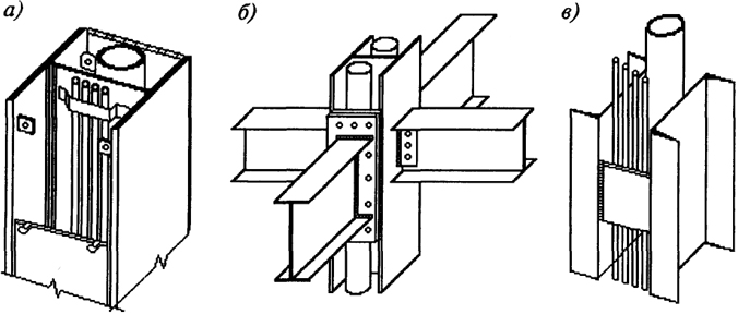
Interfacing of crossbars with columns. The type of pairing depends on the structural scheme of the frame. In communication systems, free (hinged) attachment of beams to columns is used, in frame systems - rigid.
Examples of free attachment are the design solutions shown in fig. 4.24, a...in. Similar solutions can be applied to columns with other types of sections. Free attachment on bolts of normal accuracy (Fig. 4.24, A) in comparison with other types, it is easier to manufacture and install, does not require high manufacturing accuracy, provides sufficient node compliance and practically free rotation of the beam relative to the column. Main Forces for Attachment Calculation - Shear Force in the Bearing Section of the Beam Q and longitudinal force N arising in the beam during the operation of the connection system. Only small moments occur in the node, the influence of which is taken into account when calculating the bolts by a multiplying factor of 1.2 ... 1.3 to the force Q. The vertical rib and the seams attaching it to the column should be calculated for strength Q, moment Qe, force N.
In the scheme of Fig. 4.24, b the conditions for loading the table from the corner depend on its deformations and are rather uncertain. For an approximate estimate of the eccentricity e strength Q relative to the section of the horizontal flange, in which its rounding begins (size ki from the butt), you can take the distribution of contact stresses along a triangular diagram, then e = A 0 + 2With 0 / 3 - k 1 , where size With 0 must be at least Q / (t w R y) - h 1 .
Rice. 4.24. Free attachment of beams to columns:
1
- rib; 2
- mounting table; 3
- the beginning of the rounding in the transition from the wall to the shelf; 4
- pad; 5
- milling plane #Sa
If e ≥ 9Q / (8l a R y), then the thickness of the shelf is found from the condition of its resistance to bending ta = √
, Where ta, l a- thickness and width of the corner shelf. At support pressures of more than 120 ... 150 kN, table variants with reinforcement by a vertical rib are used, for which a triangular diagram of contact stresses is also taken. Attaching the table to the column in any case should be checked for strength Q and moment Q(b - c 0 / 3). Bolts connecting the web of the beam to the column through an intermediate angle or rib are calculated on the longitudinal force. Rigid attachment of beams to a column is shown in fig. 4.25. Calculation of the structures of the node, made according to the scheme of fig. 4.25 A, has no singularities (see Section 6.8). In the node according to the scheme of Fig. 4.25 b the details of the interface with the column of the beam wall are calculated on the transverse force, the details of fastening to the flanges of the beam - on the force S = M/h. Horizontal and vertical connections. The forces from the wind load acting on the outer walls are collected in the planes of the floors and roofs and are transferred to the vertical frame elements through the rigid horizontal disks formed by load-bearing structures floors. Vertical braced trusses in braced and frame-braced frames can have various systems lattices (Fig. 4.26). The most widely used semi-diagonal lattice (Fig. 4.26, b), since it allows the device in the tie panels of door and window openings and at the same time experiences insignificant additional compression forces due to the shortening of the columns under load. The axes of the braces must pass through the points of intersection of the axes of the columns and crossbars. Adjacency with eccentricity is associated with the occurrence of moments in the bars of the lattice. IN in some cases, with appropriate requirements for the arrangement of openings, triangular ones are used (Fig. 4.26, A) schemes of the lattice of vertical bonds. The device of connections with a cross lattice is possible only in deaf wall panels. Such a grid is the most rigid and effectively works on horizontal loads that change direction during operation. Vertical truss trusses are usually performed for the entire height of the building in the same panels. However, in some cases, it is necessary to shift the links to adjacent panels, and then the lower links should go to the upper ones to the height of the floor, i.e. on the transitional floor, vertical connections should be located in two adjacent panels. The belts of vertical braced trusses, as a rule, are columns, and the racks are floor beams. The braces of vertical truss trusses are usually designed from paired corners, channels, rectangular or round pipes, and with large longitudinal forces - from I-beams (Fig. 4.27). Since the braces of the truss trusses are involved in the transmission of vertical loads, when calculating the braces and their attachment points, additional forces arising from the shortening of the building columns should be taken into account (see, paragraph 6.6.2). Fastening braces in most cases are performed on high-strength bolts. When calculating nodes, you can use the recommendations of clause 6.5. Literature for Ch. 4 1...7. See main literature. 8. Pukhovsky A.B., Arefiev V.M., Lamdon S.E., Lafishev A.Z. Multi-storey high-rise buildings. - M.: Stroyizdat, 1997. 9. Hart F., Henn W., Sontag X. Atlas of steel structures. Multi-storey buildings. - M.: Stroyizdat, 1977. 10. Shuler V. High-rise building structures. - M.: Stroyizdat, 1979. 11. Savitsky G.A. Wind load on buildings. - M.: Stroyizdat, 1972. 12. Barshtein M.F. Effects of wind on buildings and structures. / Proceedings of TsNIISK, vol. 21. - M.: 1973. 13. Romansikov I.G., Levites F.A. Fire protection of building structures. - M.: Stroyizdat, 1991.
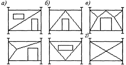
Rice. 4.26. Vertical link schemes:
A- triangular; b- semi-diagonal; V- portal; G- cross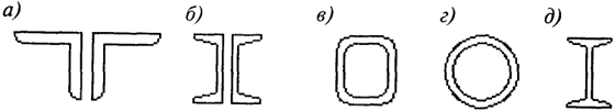
Rice. 4.27. Sections of braces of tie trusses:
A- T-shaped from two corners; b- from two channels; c, g- from closed profiles; d- I-beam
To simplify the installation process, the columns should be delivered to the construction site as long as possible. The place where the individual sections of the columns are connected to each other is called the field joint, and the sections shipped from the factory are called shipping marks. The lengths of shipping marks are limited by transport capabilities and do not exceed general case 20-22 m. The segments of the columns, determined by the length of the rolled elements, in most cases have a length of up to 15 m; for longer lengths, metallurgical plants charge a surcharge. The dimensions of the shipping marks of very strong columns are often limited by the carrying capacity of the transport and assembly mechanisms used.
Often there is a need for joints during the manufacture of columns at the factory, for example due to a change in cross-section or for other reasons.
At the junction, the segments of the column must have flat cuts strictly perpendicular to the axis of the rod. With little effort, these cuts are made with a saw. With great effort, the ends of the columns must be milled. According to current standards, part of the force at the junction can be transmitted directly through the ends. The remainder of the force is transmitted by welding or bolts. In the presence of bending moments, tensile stresses must be fully taken up by the joints.
1 and 2. The simplest welded joint is butt welds (Fig. 1), which can also be used when joining profiles of the same type with different cross-sectional areas (Fig. 2). If such a joint is performed during installation, then to temporarily fix the position before welding, it is necessary to install auxiliary wedges, linings, etc.
3. Bolted butt joint. Efforts are transmitted through pads fastened with bolts. When changing the cross section, the installation of gaskets is required (shaded part). This joint, although it does not require welding at installation, is not always acceptable due to the increase in the size of the column at the joint.
4. In columns, the joint with end plates is most often used. The plates welded to the ends of both columns must fit snugly against each other. Since the end plates warp during welding, it is sometimes necessary to re-gouge their surfaces after welding. This type of joint is also used when making factory joints, if the cross sections of the joined parts of the column differ significantly from each other. In this case, the plates are welded to each other.
5. It is often necessary to skip a run at the junction of columns. The columns have welded end plates according to the type of joint 4. The purlin is reinforced with stiffeners, through which the forces from the upper section of the column are transmitted to the lower section. The stiffening ribs must fit snugly at the top and bottom and, due to the tolerances in the rolled profiles, they must fit. With welded profiles, this adjustment is not required.
Beam connection
At the junction, the reactions of the beams are transferred to the columns. The design of the adjoining beams should:- ensure the transfer of effort; allow some movement during installation;
- be feasible by simple means, if possible without scaffolding and scaffolding.
1. Adjacency, ensuring the transmission of only transverse forces. The transverse forces transmitted from the beams cause only longitudinal forces in the columns. An abutment can be considered as hinged if it is made on bolts, since bolted connections are somewhat pliable.
2. Adjacency of continuous beams that transmit only vertical forces to the columns and do not transmit bending moments. This is achieved by the fact that the column has hinges under the beam and above the beam.
3. Very often, columns are so flexible compared to beams that even with a rigid connection between beams and columns, it can be assumed with sufficient accuracy that the columns do not perceive the bending moment from the beams.
4. In frames, shear forces and bending moments are transferred from the beams to the columns. Beam fastenings in this case are calculated for both forces.
The joints of the columns are factory and assembly. Factory joints are arranged due to the limited length of rolled profiles (see section Range). Mounting joints are arranged due to limited transport capabilities (9 - 13 m when transported on one platform and 19 - 27 mm when transported on a coupler).
Factory joints of elements are usually spaced apart, not concentrating them in one place, since the connection of individual elements can be made before the general assembly of the rod. Examples of welded factory joints of individual elements of the columns are shown in the figure.
Factory welded joints
Factory welded joints: a - welded I-beam belts; b - I-beam branches
solid column; c - branches of a through column on the slats.
The main condition for the formation of a strong joint is to ensure the transfer of force from one element to another. When butt welding, this is ensured by the appropriate length of the welds (see section Welded joints), and when butting with overlays, in addition to the required length of welds, also with the corresponding cross-sectional area of the overlays, which should not be less than the cross-sectional area of the main joined elements.
The simplest and therefore the most recommended is a straight butt weld. The implementation of such a joint is possible in all cases, since in eccentrically compressed columns one can always find a section with reduced tensile stresses.
The mounting joints of the columns are located in places convenient for the installation of structures. For columns of variable section, such a place is a ledge at the level of support of crane beams, where the section of the column changes.
Joints of the upper and lower parts of a single-walled oblique column
The figure shows the types of joints of the upper and lower parts of a single-walled solid column: factory and assembly.
The figure shows the attachment of the upper part of the column to the bottom through using a double-walled and single-walled traverse.
In columns with a lower lattice part, the upper part is attached with a piece called a traverse. The traverse works in bending like a beam on two supports and must be checked for strength; the diagram of the moments in the traverse is shown in the figure. Attaching the traverse to the branches of the column is carried out with continuous seams and is calculated on the support reaction of the traverse. To ensure the overall rigidity of the junction of the upper and lower parts of the column, horizontal diaphragms or stiffeners are placed.
Mounting joint of solid columns

The assembly joint of columns of a solid section, which transmits predominantly compressive forces, can be made using milled ends. This type of joint is used in Moscow high-rise buildings.
It is usually assumed that in columns operating predominantly in compression, it is still possible for tension to appear at any end of the section. Therefore, at the joints, it is required to ensure the perception of a conditional tensile force, which is usually taken equal to 15% of the calculated normal compressive force (of course, if there are no real tensile forces that exceed this value).
Supporting crane beams on the console
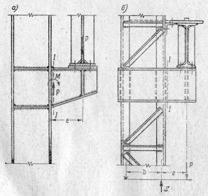
The support of crane beams on columns of constant section (in light workshops) is carried out by arranging a console from a welded I-beam (from sheets) or from two channels.
The console is calculated for the moment from the pressure of two adjacent cranes located on the crane beams: M = Pe, where e is the distance from the axis of the crane beam to the branch of the column.
The seams attaching the single-wall console are calculated for the action of the moment M and the shear force P.
The seams attaching the cantilever, consisting of two channels hugging the column, are calculated for the reaction S, found as in a single cantilever beam:
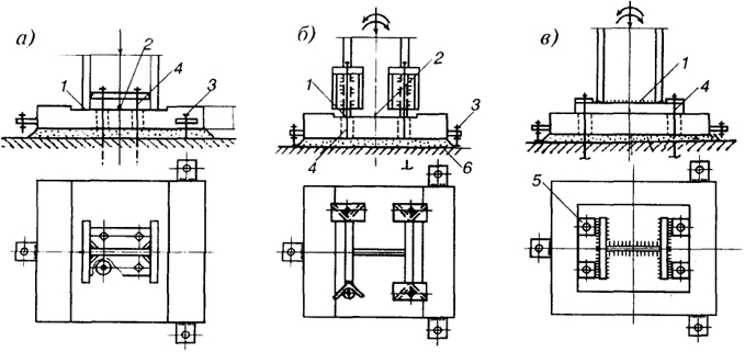
28. Structural solutions and calculation of the base of eccentrically compressed columns.
The base is the supporting part of the column and is designed to transfer forces from the column to the foundation. The base includes a plate, traverses, ribs, anchor bolts and devices for their fastening (tables, anchor plates, etc.). The constructive solution of the base depends on the type of column and the way it is connected to the foundation (rigid or hinged).
Hinged bases are similar to those used for centrally compressed columns. With high efforts, the bases of hinged frame systems are designed using support hinges (tiled, balacated). IN industrial buildings the column in the plane of the frame usually has a rigid connection with the foundation, and from the plane it has a hinged one.
There are two types of bases - shared and separate.
For solid, as well as light through columns, common bases are used (Fig. 1). For better moment transfer to the foundation, the base of an eccentrically compressed column develops in the moment action plane; the center of the slab is usually aligned with the center of gravity of the column.
If the moment of one sign is much greater in absolute value than the moment of the other sign, it is possible to design the base with a plate shifted towards the action of a larger moment.
Under the slab in the concrete of the foundation, normal stresses appear (Fig. 14.17.6), determined by the formulas for eccentric compression
At great importance bending moment, the second term of formula 14.32) may turn out to be more than the first and tensile stresses appear under the plate. Since the slab lies freely on the foundation, anchor bolts are installed to perceive possible tension, which, unlike the base of the centrally compressed column, are design elements.
The width of the slab is assumed to be 100-200 mm wider than the section of the column. Then from the condition of the strength of the foundation concrete in compression from the formula (14.32) it is possible to determine the length of the slab
The calculation is performed on a combination of force N and L(. giving the greatest edge compression of concrete.
To ensure the rigidity of the plate and reduce its thickness, traverses and ribs are installed in the base.
In light columns, bases are used with both a single-walled (see Fig. 14.16.a) and a double-walled traverse of sheets or two channels (see Fig. 14.16, V). For more powerful columns, double-walled traverses from sheets are arranged. Traverses can be common for the columns of the columns (see Fig. 14.16, ") and separate (see Fig. 14.16, *).
Common traverses are welded to the columns of the column with external seams (welding in the internal cavity is difficult). They work like two-cantilever beams under the action of the repulse of the foundation concrete and the force in the anchor bolts. The traverse fastening seams perceive only the shear force. Such traverses are suitable for small column widths (up to 540-700 mm). With a larger column width, separate traverses are more economical and convenient for welding (see Fig. 14.16, d).
Each traverse is welded to the column flange with two seams and acts as a cantilever against concrete repulsion or force in the anchor bolt. The traverse fastening seams perceive the moment and shear force.
Rice. 1. Common bases of eccentrically compressed columns.
a) a light solid column with a single-walled traverse, b) a light lattice column, c) a two-stage base with common traverses, d) a two-stage base with separate traverses. 1 - anchor bolts, 2 - anchor tiles.