How to check the wiring in a car with your own hands
In electrical installation work, one of the most important stages in the work is connecting the equipment. The successful operation of the entire complex of electrical installations at the enterprise depends on the correct execution of all operations at this stage. Before connection, power lines and cables, control circuit wires (secondary switching circuits) are laid. These circuits connect various elements of equipment with a control panel and a protection system. After installation is completed, individual wires and cables are tested before connection. In this article we will tell you why you need to test wires and cables and look at the main methods.
Concept and purpose of calling
The term continuity appeared when identifying the ends of one core in a cable; for a better understanding, we will give an example. When laying a secondary circuit cable with 12 cores, each of which has its own functional purpose, connection errors are not allowed. This could result in expensive equipment breaking down or equipment not performing certain functions.
Basic dialing methods
Detection methods depend on the cable brand and location conditions; with colored insulation of the cores, there are no problems. The cable is connected to the equipment according to the color of the cores on both sides. The difficulty arises when the insulation of all or several cores in the cable is the same color, and the cables are not marked. It is in such cases that a test is carried out, the ends on both sides of the cable are determined to belong to the same core, their integrity is determined, and markings are made.
Basic methods and equipment:
- Continuity tester, can be performed by one person within one distribution cabinet and at distances of up to 100m;
- Digital multimeter, used in similar conditions, the device is set to continuity or resistance measurement mode.
- Homemade device with lamp and batteries;
- Telephone handsets with batteries in the circuit.
- Step-down transformer complete with indicator or measuring instruments.
Sometimes you can use a megometer, but in low-voltage circuits this is not recommended for safety reasons; the device uses voltages up to 500V. This is usually done in high voltage networks over long distances to check insulation. Read also the article: → "".
Wiring continuity tester
Historically, at the initial stage of development of electrical engineering, a tester was called a pointer combined device, which includes:
- Voltmeter;
- Ammeter;
- Ohmmeter.
Then other options were added to modern devices, an electronic thermometer, light and sound indication elements, and controls and application methods were improved. As a result, instead of the old dial tester, it was replaced by its modern analogue, a digital multimeter with a liquid crystal display for displaying readings. One of the functions of the tester is wire continuity testing (checking the integrity of the wire).
Pointer combined device Ts 4342-M1. In order to ring a wire with a pointer tester, you need to carefully study the capabilities of the device, how to connect the measuring probes and in what position to put the switches on the control panel.Familiarize yourself with the discrete division of the scale; the controls and scales are different on devices of different models. Let's consider the wire testing technique using the example of a pointer tester Ts 4342-M1:
- Set the batch switch of measurement modes to the 1 kOhm position, some models have Ohm.
- Turn on the fuse button, protecting the calibrated elements of the device circuit from incorrect connection. If in continuity mode the circuits are energized.
- Press the forward and reverse current measurement mode buttons, two black buttons at the bottom of the control panel;
- Connect the probe wires to the center and right terminals to measure resistance;
- To check the functionality of the device, connect the probes to each other, the arrow on the scale should move from left to right until it stops. Measurements are carried out on a scale marked kOhm, second from the top. If the arrow moves to the right towards zero, the device is working.
The advantages of this tester are reliable protection and measurement accuracy, but in case of continuity, it works as an indicator device. Accurate readings are not required here; the following can be considered disadvantages:
- the difficulty of setting the controls to the desired mode;
- large dimensions;
- Large measurement error when batteries are discharged; supply voltage should be within 3.5 - 4.5 V.
Checking the integrity of the wire in a coiled cable
To test wires in short cords or a coiled cable, just strip the insulation on the wires at both ends and start measuring:
- Connect the probe to a wire of a certain color, the second probe is connected to a similar wire at the other end. If the arrow deviates to the zero position of the scale, the wire is in good condition.
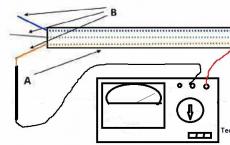
 Testing a cable with colored wires, schematic connection of probes to single-color wires at different ends of the cable. A – cable insulation. B – Individual cable cores with colored insulation.
 - With single-color wires or a laid out cable, where the distance does not allow the tester to work with different ends at the same time, all wires at one end are shorted together.
- On the other side of the cable, connect the probe to one wire and call all the other wires through it, in turn 1,2,3....

The disadvantage of this method is that it is not possible to isolate each core individually and label it. This must be done when the cable is rolled up in one place or using a transformer.
Testing wires with a multimeter
Manufacturers make different types of multimeters, but the measurement principle remains the same, only the location of the controls and measurement limits differ. To check the integrity of the wires, the measurement mode switch is placed in the continuity position; this is marked with a diode or buzzer sign. After which the dialing process is carried out using the methods described above. The integrity of the conductor, in addition to the display of zeros (no resistance), is accompanied by an audible signal or an LED indicator, this depends on the brand of the multimeter. Read also the article: → "".

The probe with the black wire is inserted into the connector with the ground symbol (housing), red above, into the connector for measuring resistance with the Ohm symbol " Ω». The disadvantage of many digital multimeters in dial mode is the delay in the sound indicator signal when touching the contacts. It is necessary to fix the probes on the wire for 2-3 seconds to make sure there is contact. This inertia in operation creates some difficulties in checking the integrity of the wire.
 Multimeters of the UNI-T type have good performance in dialing mode; the sound indicator operates almost instantly when the contacts are closed.
In other parameters, UNI-T is not inferior to other models in measurement accuracy and number of options. Read also the article: → "".
 Comparison table of characteristics of Fluke-179 and UNI-T UN61 multimeters
 Please note that for all instruments it is advisable to use probes with gold-plated rods. Unlike steel ones, they are not subject to oxidation and provide reliable electrical contact.
Continuity using a transformer
This method is effective for testing unrolled laid cables with wires of the same color. In this case, step-down transformers are used with different voltages at the taps of the secondary winding.
- The primary winding of the transformer is connected to a 220V AC source;
- The beginning of the secondary winding to the ground loop, to which the cable shield is closed;
- The remaining secondary winding taps with different voltages to the ends of the wires;
- On the other side of the cable, a multimeter is used to measure the corresponding voltage between the ground loop and the cable wires. Thus, the integrity of the core is checked and marked.
 Diagram for connecting the cable to the transformer for dialing. The multimeter is set to AC voltage measurement mode. It is recommended to use devices from Western manufacturers, since in this case the measurement mode is used, not the indication mode.
 Chinese S-99 type multimeters are very poorly calibrated; inaccurate voltage measurements can lead to errors when marking the cable. Therefore, for tapping a cable using a transformer, where voltage measurements are made, it is better to use a pointer device of the Ts-4342-M1 type.
Characteristics of the combined device Ts 4342 M1:
| Accuracy class | 2,5/4,0 |
| measurement ranges | |
| DC current in mA | 0,05 — 2500 |
| AC current in mA | 0,25 — 2500 |
| Voltage, DC | 0,1 — 1000 |
| Variable voltage in volts | 1,0 — 1000 |
| DC resistance in kOhm | 0,3 — 10000 |
| signal level when measuring voltage in dB(-) | -10 to+15 |
| frequency range in Hz | 45 — 2000 |
| Power supply | autonomous |
| Dimensions in mm | 215*115*90 |
| Weight in kg | 0,9 |
| operating temperature | from -10 to +40°С |
 In most cases, all multimeters have a classic layout of controls with minor differences. When taking measurements, you need to carefully look at the inscriptions with symbols.
 Summary table of main parameters for different models of multimeters:
| Model | LCD screen | U— | V~ | I— | I~ | R | Calling connected |
Diode testing | Transistor testing |
| M830B | 7 segments 3.5 digits |
0.1mV- 1000V |
0.1V- 700V |
0.1mA- 10A | — | 0.1W- 2mW |
— | * | * |
| M830 | 7 segments 3.5 digits |
0.1mV- 1000V |
0.1V- 700V |
0.1mA- 10A | — | 0.1mW- 2mW |
* | * | * |
| M832 | 7 segments 3.5 digits |
0.1mV- 1000V |
0.1V- 700V |
1mA- 10A |
— | 0.1W- 2mW |
* | * | * |
| M838 | 7 segments 3.5 digits |
0.1mV- 1000V |
0.1V- 700V |
1mA- 10A |
— | 0.1W- 2mW |
* | * | * |
To set the multimeter to the AC voltage measurement mode, you need to set the batch mode change switch to the sector with the icon « V~" to the maximum value within which measurements are taken. In our case, this will be any measurement limit greater than 20V; the wires from the probes are installed in the same connectors as when measuring resistance.
Making calls using handsets
The advantage of this method is that it is convenient to ring unrolled cables with wires of the same color. At the same time, electricians can communicate with each other. The disadvantage is that one person cannot do the work this way.
You will need two handsets and one battery, 4.5 volts is enough.
- Connect a 4.5 V battery into the microphone wire coming out of the handset. (Polarity does not matter). The main thing is that the current is constant and stable, without ripples, if not a battery is used, but a rectifier from an industrial network.
 Connecting the power source to the handset, please note that polarity does not matter, the main thing is that the battery is connected to the circuit in front of the microphone.
 - Connect the end of the wire connected to the capsule to the shielding sheath of the cable, the second to one of the cores;
- On the other side of the cable, the second tube is connected with one wire to the shielding sheath. The second wire is connected to different wires in turn until the installer at the other end of the cable responds.
 Connecting tubes to a cable for wire testing; the positive wire can be connected to the shielding sheath on the cable or to the metal pipe in which it is laid. But it must be taken into account that the pipe must be solid or have electrical contact with a common ground loop for both sides of the cable.
 Tip #1. To make the design easier, use a microphone headset from cell phones; in some cases this is very convenient.
 Diagram for connecting micro headphones to a handset instead of a telephone capsule.
 Testing the cable with an indicator device with a light bulb
To do this you will need any power supply, a 1.5 battery; 4.5 or 9 Volts, wires with alligator clips and a lamp for the appropriate voltage.
Assembly of the circuit and procedure for use:
- Wires are soldered to the battery terminals;
- In the break of one of the wires, the polarity does not matter, connect an LED or a lamp;
- The dialing process is carried out using the same method as with a tester or multimeter. In this case, if the conductor is intact, instead of the arrow deflecting or the reading on the liquid crystal display, the light will light.
 Such an indicator device allows you to test cables over distances of several hundred meters, depending on the state of charge of the battery.
  Connection diagram for an indicator device with a light bulb for cable testing.
 Tip No. 2 During installation work, when the lamps are constantly moving, it is recommended to use an LED. It is less susceptible to mechanical stress than a conventional incandescent lamp with a spiral and a glass bulb.
The most common mistakes made when testing cables
- Incorrect setting of measurement modes or connection of probes to the sockets of the multimeter or tester. On old pointer testers, the operating mode switch is set to the 1 kOhm position, on modern devices in the dialing mode, with a diode or buzzer sign;
- When testing wires using a step-down transformer, use a pointer tester to check the power source. The voltage should be from 3.5 to 4.5 volts, otherwise the voltage will be measured with a large error;
- Before testing, thoroughly clean the contacts on the cable wires and test leads. Gold-plated contacts do not need to be cleaned; you can wipe them with cotton wool and industrial alcohol.
It is often necessary to ring or determine the integrity of a circuit at home in order to determine the location of damage to electrical wiring or the serviceability of electrical devices: switches, lamps, transformers, fuses, electric motors, LEDs, heating elements, etc.
Unlike measuring current and voltage, continuity and any resistance measurements - Always only carried out when the circuit power is turned off.
Remember that even low voltage from a simple battery can damage the device or cause incorrect measurement results.
Continuity testing is carried out using a tester or multimeter. Before starting the process, these devices must be correctly switched to ohmmeter mode and set the measurement limit, or better, if available, in a special dialing mode with a sound signal. You will learn how to do this from our article: “How to use a multimeter” or from the instructions for the device.
If there is continuity in the circuit, the multimeter gives a signal and numbers indicating the resistance are displayed. If the circuit is broken, then too much resistance or one digit 1 in the most significant digit, or the letters “O.L.” is displayed on the screen.
With a pointer tester, if the circuit is intact, the needle should deviate to the last division.
Always short-circuit the probes before starting the test to ensure the functionality of the measuring device.
In my daily work as an electrician, I use the “Contact+” universal electrician tester (in the picture on the right), which allows you to determine the presence of voltage of 12, 220 and 380 Volts, and of course test the circuit with sound and light indication. It is compact and easy to use.
I do not recommend using multifunctional indicator screwdrivers for dialing, which I talked about in this article, because they often, due to interference, show the integrity of the circuit, which in reality is broken.
Before ringing any device, familiarize yourself with its structure, because very often their circuit contains capacitors that continue to store electrical charge and after stress is relieved.
How to ring electrical wires or cables.

How to ring a diode.
The essence of the diode's operation is that it passes electric current only in one direction - the resistance is close to zero, and in the other - it is very high, i.e. it does not pass. To check, we apply test leads, and then swap them to change the polarity. If the diode only passes in one direction, it means it is working.
How to ring an LED.
An LED is not a simple diode, it can only operate within a certain voltage range. If the voltage at its contacts is low, then its “resistance” will tend to infinity.
If you call with an inexpensive multimeter, then with the correct polarity the diode may glow dimly, but with expensive ones  There is no reaction from the models at all.
If you want to make sure the integrity of the LED, connect it, observing safety precautions and polarity, to a direct current source with the appropriate voltage but low current.
If the LED is not soldered it can be checked with a multimeter by setting it to transistor test mode (hFE, as shown in the picture on the right). After this, we take any LED and insert its anode terminal into connector E (emitter), and the other contact leg into connector C (collector), as shown in the figure. If the LED is working properly, it will light up.
How to dial a transformer.
With a transformer, you can only test the integrity of both windings, but interturn short circuits will not be possible.
It is verified correctly and reliably as follows. We select a fuse based on the power of the transformer and connect it through the fuse to the socket without connecting the load on the secondary winding. If it gets very hot or the fuse blows, then it has an interturn short circuit in one of the windings.
How to ring ten.

- We connect the measuring probes to two contact legs of one heating element or heating element. Be careful, there may be two of them in one building.
- If readings with a slight resistance appear on the screen of the multimeter or tester (as in the left picture), then it is working. If a one appears on the left or very high resistance - this means a break inside the heating element and it will have to be replaced.
- Besides it is necessary to ring the contacts of the heating element on the body. If they ring (as in the right picture), it means there has been a breakdown of the insulation on the housing. The heating element will have to be replaced, otherwise there will be a current leak to the housing, which can lead to electrical injury.
How to ring a lamp.
For incandescent lamp We put one probe on the central contact, and the other on the side; if you hear a sound signal and see a resistance from 3.5 to 200 Ohms on the display, then the lamp is intact. If there is no signal, it's time to throw it away.
For tubular fluorescent lamps there is one spiral on both sides, so both must ring.
LED and compact fluorescent You can't check the lamps with a tester. This can only be done by applying voltage.
How to ring a fuse.
 Any fuse inside has a current-carrying wire of a certain thickness, which is designed for a certain current strength; if this limit is exceeded, it will burn out. A good fuse shows a resistance of 0 ohms on the display and gives an audible signal.
The automatic plug is checked in the same way, only the wire in it does not burn out, but knocks out the bimetallic plate, so before checking, make sure that it is turned on.
How to dial an electric motor.
A tester or multimeter can only check the integrity of the armature or stator windings, but it is only possible to fully measure the insulation resistance with a rather expensive device called megohmmeter, which produces several times higher voltage during testing (500 or 1000 volts).
A full check, as well as the continuity of the electrical wiring, is a mandatory stage in the renovation of any apartment. In addition, it is also necessary to ring the wiring if there are doubts about its serviceability. Naturally, the easiest way to check the serviceability of the electrical wiring of the apartment is to contact a specialist, i.e. to an electrician. But municipal services do not work promptly in this regard, and private specialists charge a lot for such services.
Therefore, today experts in electrical matters strongly recommend that everyone independently master the most basic and primary skills of working with. Sooner or later, they will absolutely come in handy in your life!
First of all, you need to know that during absolutely any manipulations related to electrical wiring, you must strictly observe all the rules and requirements dictated by safety precautions for electrical work.
Checking the electrical wiring
Checking the electrical wiring at the installation stage
First of all, at this stage of the inspection, it is necessary to pay attention and determine those potential problems that there is a real possibility of encountering in the process of laying new electrical wiring. Typically, wiring is laid along bare walls. After this, they are covered with plaster, and the walls in the room are finished.
It is necessary to check all electrical wiring for the first time before starting all plastering work; this process applies to any type of building, be it in an apartment! If this is not done, then you may be in for an unpleasant surprise in the future, in which, in order to eliminate various types of problems with electrical wires, you will need to open the plaster, and after finishing the work, plaster everything again.
Electrical wiring diagram
At this stage, the sources of possible problems that may arise in hidden electrical wiring are conditionally divided into two main groups.
- The first of them is the mistakes of craftsmen, such as plasterers, concrete workers, builders, finishers, etc.).
- The second is the electrician’s mistakes.
The first group of problems can be dealt with only by vigilant supervision. But electrician mistakes can be avoided in advance. To do this, you must carefully follow the drawn electrical wiring diagram during its installation, and also carefully check it before starting the finishing work stage.
Easy testing of new electrical wiring
There are several tips you can use to make sure it's working properly. You need to check it to see if there is a short circuit. That is, there should be no contact between ground and zero, phase.
The level of quality of insulation of electrical wires at high voltage depends directly on the quality of the cable. That is, you need not to skimp and purchase a not very cheap version of the materials, and then problems, most likely, will not arise.
If you are not sure about the quality of the insulation, then it can be checked using a megohmmeter. Often, in most hardware stores, such a service is provided on site upon purchase.
The next stage of inspection is visual inspection of the condition and quality of the cable insulation. All mechanical damage must be eliminated before the cable is covered with plaster or finishing material.
Checking the outlet
In the case when everything is fine at the previous stage, it is possible to move on to the next stage of testing - you need to check the wiring (this stage is also very important when). Each owner of the premises does not care to familiarize himself with the description of the dialing procedure in as much detail as possible. Using a certain algorithm, it is possible to check not only new wiring, but also those located in a residential apartment or house.

Calling the wiring
Dialing tools
Wiring testing is usually done with a special device - a multimeter, which is designed to record all kinds of electrical connection parameters (voltage, current, resistance, etc.). Today, multimeters come in analog and digital forms, but the operating principle of these devices always remains the same.
- Testing wiring using a multimeter
- Checking connections
First of all, you need to set the dial mode on the multimeter - this is often indicated by an LED.
Then you should go to the place where the electrical wiring is ringing, i.e. to the junction box. As a rule, there appears before your eyes a bunch of unmarked wires.
You need to find the phase - turn on the machine, check all the wires using an indicator screwdriver. In this case, the found wire should be marked using insulating tape, as well as tape that is intended for covering windows.
Next you need to find zero. Turn on the device to measure voltage (then when we need to find 220V, we should set it more - 600V for a number of models). Then you need to touch the phase with one probe of the multimeter, and with the other end of the device you should test the electrical wires one by one. As soon as 220V appears on the device, it means that the wire that was needed has been found. It must be marked.
Then you need to check other pairs of electrical wires according to this principle and label them.

Conductor integrity check
In order to check the integrity of the electrical wiring, we need to perform the following steps:
- The conductor should be disconnected from the current source itself. If the conductor is a multi-core cable, you need to do this for all the wires that go into it.
- Then you need to turn on the device either in the dialing mode, or in the resistance measurement mode, but always at the roughest possible limit.
- After this, you need to connect the multimeter probes. In this case, zeros should appear on the device display. At the same time, in the ringing mode, which has sound accompaniment, the multimeter will make a squeak.
- Next you need to connect the open probes of the device to the conductor. You need to know that the whole conductor, at the same time, shows zero resistance.
Testing electrical wires in an apartment, as well as searching for cable breaks or short circuits, can be done efficiently independently - without the involvement of an expensive specialist, and if you have one, there is no need to call a specialist at all.
The main thing is to approach this issue consistently and strictly adhering to the above recommendations of professional electricians. And of course, be sure to remember that even if it seems to you that you are already a fully experienced electrician, you should not forget about following safety rules!
Video: How to use a multimeter
Preparing the Multimeter
In order to test wires and cables, an inexpensive multimeter with a resistance measurement mode is suitable. Let's take the DT-838 multimeter as an example.
How to test wires with a multimeter
To test wires and cables, two measurement modes are used - “200 Ω” and sound image. The difference between these modes is that in the “200 Ω” mode, when dialing, the display shows a resistance value close to zero if the wire is intact, and 1 if it is broken.
In the audible alarm mode, the display shows the resistance value when dialing and adds an audible alarm. The appearance of a sound signal means the wire resistance is close to zero. And its absence means high resistance or a broken wire.
This sound alarm is convenient for dialing in hard-to-reach places where it is not possible to observe the multimeter display. However, before testing high-voltage wires with a multimeter in a car, the measurement limit is set to “20 K,” since the resistance of an entire high-voltage wire ranges from 3.5 to 10 K.

Before testing the wire with a multimeter, a probe with a black wire is inserted into the “COM” socket, and a red probe into the “ΩVmA” socket. The mode switch must be set to the measurement limit of “200 Ω” or sound alarm. Before testing wires and cables, the probes are connected to each other to check the functionality of the device.
How to connect wires
Before measurements, it is important to strip the ends of the wires from insulation and remove oxide from the cable cores. The oxide on the wires may have high resistance, which will be higher than the limit of the selected resistance mode of the device, which will give incorrect readings.
Before making the call, you need to remove the mains voltage from the electrical wiring and remove the terminals from the battery in the car. If there are capacitors in the wire continuity circuit, then they need to be discharged by short-circuiting the terminals. All these precautions will help avoid damage to the multimeter and give more reliable results.
For convenience, when making calls, use special wire clips - “crocodiles”. The “crocodile” is put on the probe and clamped onto a section of the wire. The use of such clamps increases the convenience of working with wires, as your hands are freed.
Short cables and wires can be tapped at one end, while long wires must be thoroughly cleaned of oxides and twisted together on one side. Then the dialing process is carried out only on one side. You can ring the wires without a multimeter. For such purposes, electricians use a specially made “dialer” consisting of a battery and a light bulb. A sound generator and headphones are also used to check cables and wires.

Determining a fault in electrical wiring
Let's look at the finding using standard electrical wiring as an example. Before electrical work, you need to remove the voltage from the input circuit breaker in the electrical panel. If the machine in the switchboard knocks out, then the procedure for finding a short circuit is as follows:
- Remove the voltage from the knocked-out input circuit breaker, unscrew the wires from the lower terminals of the circuit breaker, the cable should go to the load from the lower terminals of the circuit breaker.
- The disconnected phase and neutral wires on the switchboard ring. If there is a short circuit, unwind all the wires in the first junction box from the electrical panel and ring them. Each wire in the box is marked before unwinding, one twist under one number. Find the direction (room) of the electrical wiring with a short circuit.
- Before dialing, all lighting fixtures in all rooms must be turned off and plugs removed from sockets. If everything is turned off, and a short circuit is present in the distribution box of this room, unwind the wires in the box and use a multimeter to look for a short circuit, separately for each outlet and lighting. If a short circuit occurs when the lighting is on, the fault is looked for in the lamp socket or chandelier.
- Any section of electrical wiring that is found to have a short circuit needs to be replaced. If the electrical wiring is hidden, then you need to open it (which is expensive) or run a cable channel along the top of the wall. The cable duct spoils the view a little, but the costs are minimal.
- If the wiring fault is a break, then the break location is found with the input circuit breaker turned on to check for the absence of voltage. The multimeter mode is set to “~750V”, do not confuse it with the resistance measurement mode, otherwise the multimeter will burn out. The exact location of the break can be found by applying voltage to this section of the circuit and using special devices (domestic “Woodpecker”).
If you find a break or
When carrying out electrical installation work, it may be necessary to test the cable, for example, when marking cores and wires, checking the insulation and integrity of the wiring, as well as searching for a broken electrical cable. Let's consider the ways in which testing can be carried out, as well as the equipment necessary for this purpose.
Methods
Testing methods depend on the purpose for which it is performed. To check the integrity of the cable for a break or electrical connection between its wires (short circuit), the continuity test can be done with a tester based on a battery and a light bulb, or you can use a multimeter for this purpose. The latter is preferable.
Despite the fact that the price of a multimeter is higher than a primitive device, we recommend buying it; this device will always be useful in the household.
To check the cable, the multimeter must be turned on in the appropriate mode (diode or buzzer image).

The testing methodology is as follows:
When checking a wire for a break, the tester is connected to its ends as shown in the figure. If the cable is intact, the light will glow (when testing with a multimeter, a characteristic sound signal will be heard).

Explanations for the picture:
- A – electrical cable;
- B – cable cores;
- C – power source (battery);
- D – light bulb.
If the cable has already been laid, then on one side it is necessary to connect the wires together and ring the wires at the other end;

when checking the presence of an electrical connection between the cable cores, the tester probes are connected to different wires. Unlike the previous example, there is no need to twist the wires on the other side. If there is no short circuit between the wires, the light will not light (when testing with a multimeter, no beep will sound).
Testing multi-core cables for the purpose of marking them
When marking multi-core cables, you can use the methods described above, but there are ways to significantly simplify this process.
Method 1: the use of special transformers that have several secondary winding taps. The connection diagram for such a device is shown in the figure.
As can be seen from the figure, the primary winding of such a transformer is connected to the power supply network, one end of the secondary winding is connected to the protective shield of the cable, and the remaining terminals are connected to its conductors. To mark the wires, it is necessary to measure the voltage between the screen and each wire.
Method 2: Using a block of resistors with different values connected to the cable wires on one side, as shown in the figure.

To identify the cable, it is enough to measure the resistance between it and the screen. If you want to make such a device with your own hands, then you should select resistors in increments of at least 1 kOhm to reduce the influence of wire resistance. Also, do not forget that the value of the resistors has a certain error, so first measure them with an ohmmeter.
When checking a multi-core telephone cable, installers often use a dialing headset, for example TMG 1. Actually, these are two telephone handsets, one of which is connected to a 4.5 V battery. Such a simple device allows you not only to check the cable, but also to coordinate your actions during installation and testing.

Insulation check
To test insulation with a megohmmeter or multimeter, the principle of continuity is the same as when searching for an electrical connection between the cable cores.
The testing algorithm is as follows:
- set the maximum range on the device – 2000 kOhm;
- connect the probes to the wires and see what the device display shows. Considering that the wires have a certain capacitance until it is charged, the readings may vary. After a few seconds, the device display can display the following values:
- one, this indicates that the insulation between the wires is normal;
- zero – there is a short circuit between the cores;
- some average readings, this can be caused either by a “leak” in the insulation or by electromagnetic interference. To determine the cause, switch the device to the maximum range of 200 kOhm. If the insulation is faulty, the display will display stable readings; if they change, then we can confidently talk about electromagnetic interference.
Attention! Before checking the insulation of the electrical wiring, it must be de-energized. The second important point is that when taking measurements, do not touch the probes with your hands, this can introduce errors.
Video: Wire continuity check - integrity check.
Finding the break point
After a break in the electrical wiring has been discovered, it is necessary to localize the place where it happened. For dialing in this case, you can use a tone generator, for example, the Cable Tracker MS6812R or TGP 42. Such devices allow you to determine the location of the break with centimeter accuracy, as well as determine the route of hidden wiring; in addition, the devices have other useful functions.

Devices of this type include an audio signal generator and a sensor attached to an earphone or speaker. When the sensor approaches the place where the UTP cable pairs or electrical wiring wires are broken, the tone of the sound signal changes. When a tone test is performed, the wiring must be de-energized before connecting the sound generator, otherwise the device will be damaged.
Note that with the help of this device you can test both power and low-current cables, for example, check the integrity of twisted pair cables, radio wiring or communication lines. Unfortunately, such devices will not allow you to determine the correct connection; special equipment is used for this purpose - cable testers.
Cable testers
This class of devices allows you to check both the integrity of the cable and the correctness of its connection, which is very important for Internet provider networks. These can be simple devices that check crossover or complex devices on a PIC controller that have an ADC and a built-in multiplexer.
 Multipurpose cable tester Pro’sKit MT-7051N on a microcontroller
 Naturally, the cost of such devices does not encourage their household use.
Homemade contactless dialing
Below is a diagram of a simple non-contact break detector; it can be assembled within one evening. Considering the small number of parts, you don’t have to bother making a printed circuit board, but use wall mounting.

List of required radio components:
- variable resistance R1 – 100 kOhm;
- resistor R2 – from 4 to 8 MOhm;
- electrolytic type capacitors: C1 and C3 – 220 µF, C2 – 33 µF;
- ceramic capacitor with a capacity of 0.1 μF;
- D1 – LAG 665 chip (preferably in a DIP package);
- SP is a regular earphone from a telephone headset.
The circuit can be powered from a source with a voltage of 2 to 5 volts.
The dipstick (P) is made on the basis of a regular spoke from a bicycle wheel.
Properly assembled contactless cable testing does not require adjustment.
Video: Do-it-yourself cable testing. How to test wires using a light bulb and battery