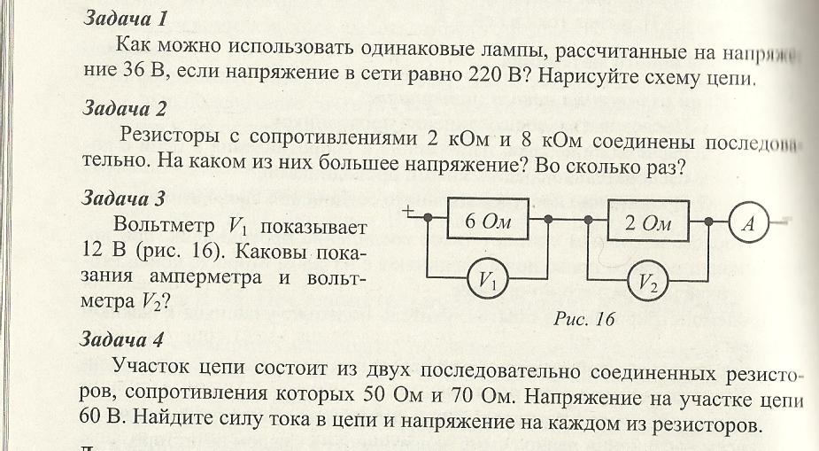
Lesson summary “Solving problems for serial and parallel connection of conductors. Series and parallel connection of conductors
Fundamentals > Tasks and Answers > Direct Electric Current
Series and parallel connection of conductors
Additional resistors and shunts
1
What R should be taken so that a lamp rated for voltage can be connected to a network with a voltage of V \u003d 220 V V o \u003d 120 V and current I o \u003d 4 A?
Solution:
2 Two arc lamps and resistance R are connected in series and connected to a network with voltage V =110V. Find the resistance R if each lamp is rated for voltage V o \u003d 40 V, and the current in the circuit I \u003d 12 A.
Solution:
Resistance voltage ![]()
Ohm's law
from here
3
To measure the voltage in a section of the circuit, two voltmeters are connected in series (Fig. 88). The first voltmeter read V 1 = 20 V, the second is V2 = 80 V. Find the resistance of the second voltmeter R 2
if the resistance of the first voltmeter R 1 = 5 kOhm. 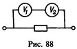
Solution:
The same current I flows through voltmeters. Since the voltmeter shows the voltage across its own resistance, then
and the resistance of the second voltmeter
4 An iron wire rheostat, a milliammeter and a current source are connected in series. At a temperature to = 0 ° C, the resistance of the rheostat Ro = 200 Ohm. The resistance of the milliammeter R \u003d 20 Ohm, its indication I o = 30 mA. What current I t will show a milliammeter if the rheostat heats up to a temperature of t \u003d 50 ° C? Temperature coefficient of resistance of iron.
Solution:
5 A conductor with a resistance R = 2000 Ohm consists of two parts connected in series: a carbon rod and a wire having temperature coefficients of resistance. How should the resistances of these parts be chosen so that the total resistance of the conductor R does not depend on temperature?
Solution:
At a temperature t, the total resistance of the series-connected parts of the conductor with resistances R1 and R2 will be
where R 10 and R 20 - resistance of the carbon rod and wire at t 0
\u003d 0 ° C. The total resistance of the conductor does not depend on temperature if ![]()
In this case, at any temperature ![]()
From the last two equations we find
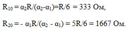
6 Draw up such a wiring diagram for lighting a corridor with one bulb, which allows you to turn the light on and off independently at any end of the corridor.
Solution:
Wiring diagrams that allow you to turn on and off the light bulb at any end of the corridor are shown in fig. 347. At the ends of the corridor, two switches P1 and P2 are installed, each of which has two positions. Depending on the location of the outlets from the network, it may be more profitable in terms of saving wires option a) or b). 
7
Two light bulbs with the same resistance are connected to a network with a voltage of V \u003d 120 V R = 200 Ohm. What current will go through each light bulb when they are connected in parallel and in series?
Solution:
I 1 \u003d V / R \u003d 0.6 A at parallel connection; I 2
\u003d V / 2R \u003d 0.3 A with a serial connection.
8
A sliding contact rheostat connected according to the circuit shown in fig. 89 is a potentiometer (voltage divider). When moving the potentiometer slider, the voltage removed from itVx changes from zero to the voltage at the terminals of the current source V. Find the dependence of the voltage Vx on the position of the slider. Construct a graph of this dependence for the case when the impedance of the potentiometer Ro is many times less than the resistance of the voltmeter r . 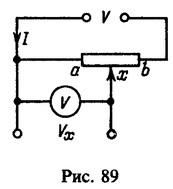
Solution: 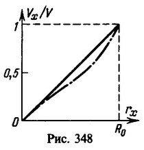 Let, at a given position of the slider, the resistance of the section ax of the potentiometer is equal to r X (Fig. 89). Then the total resistance of this section and the voltmeter (they are connected in parallel)
![]() and the resistance of the rest of the potentiometer xb isThus, the impedance between points a and b will be
and the resistance of the rest of the potentiometer xb isThus, the impedance between points a and b will be
Current in the circuit I= V/R. Voltage on section ah
Since by condition R 0
<
those. voltage V X proportional to the resistance r X . In turn, the resistance r X proportional to the length of the section ax.
On fig. 348 the solid line shows the dependence of V x from r x , dash-dotted line - dependence V x from r x when R 0 ~r, i.e. when in the expression for V X the first term in the denominator cannot be neglected. This dependence is not linear, however, in this case V x varies from zero to the voltage at the source terminals V.
9
Find the resistance R of a bimetallic (iron-copper) wire of length l =100m. The diameter of the inner (iron) part of the wire is d=2 mm, the total diameter of the wire is D=5 mm. Resistivity of iron and copper. For comparison, find the resistance of iron and copper wires Rzh and Rm of diameter D and length l
Solution:
Sectional areas of the iron and copper parts of the wire
(Fig. 349). Their resistance
The resistance R of a bimetallic wire is found by the formula for parallel connection of conductors:
Resistance of iron and copper wires of diameter D and length l
10
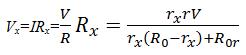
Find the total resistance of the conductors included in the circuit according to the circuit shown in fig. 90,if resistance R 1 = = R 2 = R 5 = I 6 = 1 ohm, R3 = 10 ohm, R4 = 8 ohm. 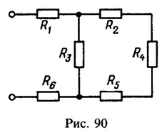
Solution:
11 Total resistance of two series-connected conductors R \u003d 5 Ohm, and parallel connected R o \u003d 1 .2 ohm. Find the resistance of each conductor.
Solution:
When two conductors with resistances R1 and R2 are connected in series, their total resistance is
and in parallel connection
from here ![]()
According to the well-known property of the reduced quadratic equation (Vieta's theorem), the sum of the roots of this equation is equal to its second coefficient with the opposite sign, and the product of the roots is a free term, i.e. R1 and R2 must be the roots of the quadratic equation
from here
Substituting the values of Ro and R, we find R1 = 3 ohms and R2 = 2 0m (or R1 = 2 ohms and R2 = 3 ohms).
12 Leading wires are connected to the wire ring at two points. In what ratio do the attachment points divide the circumference of the ring if the total resistance of the resulting circuit is n \u003d 4.5 times less than the resistance of the wire from which the ring is made?
Solution:
The connection points of the supply wires divide the circumference of the ring in a ratio of 1:2, i.e., they are 120 degrees apart from each other in an arc.
13
In the circuit shown in Fig. 91, ammeter shows current I \u003d 0.04 A, and the voltmeter - voltage V \u003d 20 V. Find the resistance of the voltmeter R 2
if the conductor resistance R 1 = 1 kOhm. 
Solution:
14
Find resistance R 1
light bulbs according to the readings of a voltmeter (V \u003d 50 V) and an ammeter ( I \u003d 0.5 A), connected according to the circuit shown in fig. 92 if the resistance of the voltmeter R 2 = 40 kOhm. 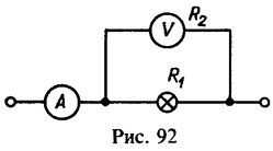
Solution:
Current in the common circuit I=I 1 +I 2 , where I 1 and I 2 - currents flowing through a light bulb and a voltmeter. Because
Neglecting the current I2 = 1.25 mA compared to I = 0.5 A, we obtain by the approximate formula
the same light bulb resistance value: R1 = 100 ohms.
15
Find the conductor resistance R 1
according to the readings of the ammeter ( I \u003d 5 A) and a voltmeter ( V \u003d 100V), connected according to the circuit shown in fig. 93 if the resistance of the voltmeter R 2
= 2.5 kOhm. What would be the error in defining R 1
if, assuming that, in the calculations to neglect the current flowing through the voltmeter? 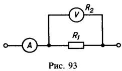
Solution:
Voltmeter reading ![]()
where I1 and I 2-currents flowing through the resistance and the voltmeter. Total current
from here
If we neglect the current I2 compared to I, then the desired resistance ![]()
Error in definition of R` 1 will
Given that
find relative error:
16
Two conductors with the same resistances R are connected in series to a current source with a voltage V. What will be the difference in the readings of voltmeters with resistances R and 10R,if they are alternately connected to the ends of one of the conductors?
Solution:
Voltmeters with resistances R and 10R show voltages
so the difference in voltmeter readings
17
Two light bulbs are connected to a current source with a voltage of V = 12 V (Fig. 94). Circuit section resistance r1=r2=r3=r4=r = 1.5 ohm. Bulb resistance R 1=R2 = R = 36 Ohm. Find the voltage at each light bulb.
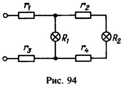
Solution: 
18
In the diagram shown in fig. 95, the voltage of the current source is V=200 V, and the resistance of the conductors R 1 \u003d 60 Ohm, R 2 \u003d R3 \u003d 30 Ohm. Find the voltage across the resistance R 1
.
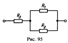
Solution: 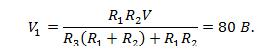
19
An electrical circuit consists of a current source with a voltage V =180V and a potentiometer with an impedance R = 5 kOhm. Find the readings of the voltmeters connected to the potentiometer according to the circuit shown in fig. 96. Voltmeter resistance R 1 \u003d 6 kOhm and R 2 \u003d 4 kOhm. Engine x stands in the middle of the potentiometer.
Solution: 
20
Three resistors are connected according to the circuit shown in fig. 97. If the resistors are included in the circuit at points a and b , then the resistance of the circuit will be R = 2 0
Ohm, and if at points a and c, then the resistance of the circuit will be R o \u003d 15 O m. Find the resistance of the resistors R 1 , R 2 , R 3 if R 1 =2R 2 . 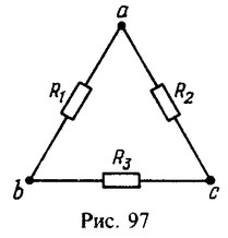
Solution: 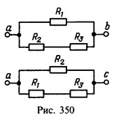 Equivalent switching circuits are shown in fig. 350. Resistance of rheostats
![]()
21 Into how many equal parts should a conductor with a resistance of R = 36 Ohm be cut, the resistance of its parts connected in parallel was Ro - 1 Ohm?
Solution:
The entire conductor has a resistance R = nr, where r is the resistance of each of the n equal parts of the conductor. With a parallel connection of n identical conductors, their total resistance is R0 = r/n. Eliminating r, we get
n can only be a positive integer greater than one. Therefore, solutions are possible only in cases where R/Rо = 4, 9, 16, 25, 36,... In our case ![]()
22
A cube-shaped frame is made of wire (Fig. 98), each edge of which has resistance r . Find the resistance R of this frame if the current I in a common chain goes from vertex A to vertex B.
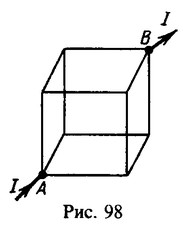
Solution: 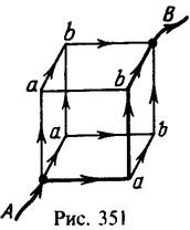 In sections Aa and bB (Fig. 351), due to the equality of the resistances of the edges of the cube and their identical inclusion, the current I evenly branches into three branches and therefore in each of them is equal to I / 3. In sections ab, the current is equal to I / 6, since at each point a the current again branches along two ribs with equal resistances, and all these ribs are connected in the same way.
Voltage between points A and B is the sum of the voltagein section Aa, voltageon section ab and voltage in section bB:
23
From wire, the unit of length of whichhas resistance R l , a frame is made in the formcircle radius r , crossed by two mutuallyperpendicular diameters (Fig. 99). Find the resistance Rx of the frame if the current source is connected to points c and d. 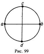
Solution:
If the current source is connected to points c and d, then the voltages in sections da and ab are equal, since the wire
homogeneous. Therefore, the potential difference between points a and b is zero. There is no current in this section. Therefore, the presence or absence of contact at the point of intersection of the conductors ab and cd is indifferent. resistance R x , thus, is the resistance of three conductors connected in parallel: cd with a resistance of 2rR 1
, cad and cbd with the same resistance p rr 1 . From the relation
24 Wire length L= 1 m gossip of three cores,each of which is a piece of uninsulated wire with unit length resistance R l = 0.02 Ohm/m. Voltage is applied to the ends of the wire V \u003d 0.01 V. How much D I the current in this wire will change if a piece of length is removed from one core l \u003d 20 cm?
Solution:
25
The current source is initially connected to two adjacent vertices of the wire frame in the form of a regular convex n -gon. Then the current source is connected to the vertices located through one. In this case, the current decreases by 1.5 times. Find the number of sides n-gon.
Solution:
n=5.
26
How to connect four conductors with resistances R 1 \u003d 10m, R 2 \u003d 2 0m, R3 \u003d 3 ohms and R 4 = 4 0m to get resistance R = 2.5 ohm?
Solution: 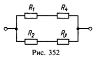 Resistance R \u003d 2.5 ohms is achieved when the conductors are connected according to the sour cream connection scheme (Fig. 352).
27
Find conductivity k a circuit consisting of two consecutive groups of conductors connected in parallel. The conductivities of each conductor of the first and second groups are equal k1 =0.5Cm and k2 \u003d 0.25 See. The first group consists of four conductors, the second of two.
Solution:
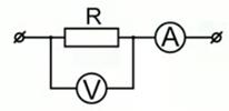
28 The voltmeter is designed to measure voltages up to the maximum value V o \u003d 30 V. In this case, a current flows through the voltmeter I =10 mA. What additional resistance Rd needs to be connected to a voltmeter so that they can measure voltages up to V=150V?
Solution: 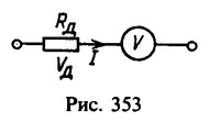 To measure higher voltages with a voltmeter than those for which the scale is designed, it is necessary to connect an additional resistance Rd in series with the voltmeter (Fig. 353). The voltage on this resistance Vd = V-Vo; therefore, the resistance Rd \u003d (V-Vo) / I \u003d 12 kOhm.
29 The arrow of the milliammeter deviates to the end of the scale if current flows through the milliammeter I \u003d 0.01 A. Instrument resistance R = 5 0m. What additional resistance Rd needs to be connected to the device so that it can be used as a voltmeter with a voltage measurement limit V = 300 V?
Solution:
To measure voltages not exceeding V by the device, it is necessary to include in series with it such an additional resistance Rd so that V = I (R + Rd), where I is the maximum current through the device; hence Rd \u003d V / I-R 30 kOhm.
30 Voltmeter connected in series with resistance R 1 \u003d 10 kOhm, when connected to a network with voltage V =220V indicates voltage V 1 = 70 V, and connected in series with the resistance R 2 , shows voltage V2 = 20 V. Find the resistance R 2.
Solution:
31 Voltmeter with resistance R = 3 kOhm, included in the city lighting network, showed voltage V =125V. When the voltmeter is connected to the network through the resistance Ro, its reading decreases to V o \u003d 115 V. Find this resistance.
Solution:
The city lighting network is a current source with an internal resistance much lower than the resistance of the voltmeter R. Therefore, the voltage V = 125 V, which the voltmeter showed when connected directly to the network, is equal to the voltage of the current source. This means that it does not change even when the voltmeter is connected to the network through the resistance Ro. Therefore, V \u003d I (R + Ro), where I \u003d Vo / R is the current flowing through the voltmeter; hence Rо = (V-Vо) R/Vо = 261 Ohm.
32
A voltmeter with a resistance R = 50 kOhm, connected to a current source together with an additional resistance Rd = 120 kOhm, shows the voltage V o \u003d 100 V. Find the voltage V current source.
Solution:
The current flowing through the voltmeter and additional resistance, I=Vo/R. Current source voltage V = I (R + Rd) \u003d (R + Rd) Vo / R = 340 V.
33
Find the reading of the voltmeter V with resistance R in the circuit shown in fig. 100. The current before branching is I , conductor resistance R 1 and R 2 are known. 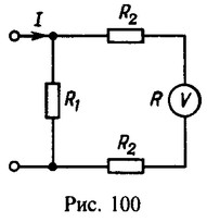
Solution:
34 There is a device with a division price i 0 \u003d 1 μA / div and the number of divisions of the scale N = 100. Device resistance R = 50 Ohm. How can this device be used to measurecurrents up to I \u003d 10 mA or voltages up to V \u003d 1 V?
Solution:
To measure higher currents than those for which the scale is designed, a shunt with resistance is connected in parallel with the device
to measure voltages, an additional resistance is connected in series with the device- the current flowing through the device at the maximum deflection of the needle,
- the voltage at its terminals in this case.
35 milliammeter with limit measurement of currents I 0 = 25 mA must be used as an ammeterwith current measurement limit I \u003d 5 A. What resistance Rsh should the shunt have? By how much does the sensitivity of the device decrease?Instrument resistance R= 1 0 Ohm.
Solution: 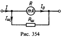 When a shunt is connected in parallel to the device (Fig. 354), the current I must be divided so that a current Io flows through the milliammeter. In this case, current Ish flows through the shunt, i.e. I \u003d Io + Ish. The voltages on the shunt and on the milliammeter are equal: IоR = IshRsh; from here
Rsh \u003d IoR / (I-Io)0.05 ohm. The sensitivity of the device decreases, and the division value of the device increases by n=I/Io=200 times.
36 Ammeter with resistance R = 0.2 Ω, short-circuited to a current source with voltage V= 1 ,5V, indicates current I \u003d 5A. What current I 0 will show the ammeter if it is shunted with resistance R w \u003d 0.1 Ohm?
Solution:
37
When shunting the galvanometer with resistances R 1
, R2 and R3 they branch off 90%, 99% and 99.9% of the current I common chain. Find these resistances if the resistance of the galvanometer R = 27 Ohm.
Solution:
Since the shunts are connected to the galvanometer in parallel, the condition of equality of voltages on the galvanometer and on the shunts gives
from here
38 A milliammeter with a number of divisions of the scale N = 50 has a division value i 0 = 0.5 mA/div and resistance R = 200 Ohm. How can this device be adapted to measure currents up to a value I = 1 A?
Solution:
The highest current flowing through the device, Iо = iоN. To measure currents that significantly exceed the current Iо, it is necessary to connect a shunt in parallel with the device, the resistance of which Rsh is much less than the resistance of the milliammeter R:
39 To an ammeter with resistance R = 0.1 ohm connected shunt with resistance R w = 11.1 mΩ. Find the current flowing through the ammeter if the current in the common circuit I \u003d 27 A.
Solution:
The current flowing through the shunt, Ish \u003d I-Io. The voltage drops on the shunt and the ammeter are equal: IshRsh = IoR; hence Io \u003d IRsh / (R + Rsh) \u003d 2.7 A.
40
Parallel to ammeter with resistance R = 0.03 ohm included copper conductor length l =10 cm and diameter D =1.5mm. Find the current in the circuit I if the ammeter shows current I o \u003d 0.4A. Resistivity of copper.
Solution:
Pestrechinsky municipal district of the Republic of Tatarstan
Solving problems for serial and parallel connection of conductors.
Compiled by:
Latypova Gulnazira Khilalutdinovna,
physics teacher of the highest qualification category MBOU "Pestrechinskaya secondary school No. 1
with in-depth study of individual subjects "
Pestretsy 2013
The purpose of the lesson:
1) educational - to ensure the assimilation of the laws of series and parallel connection of conductors,
2) developing - continue to form the skills of working with physical devices and generalize the results of experiments,
3) educational - to develop cognitive interest in the subject, to train the memorization of formulas.
Lesson objectives:
Learn that the current strength is directly proportional to the voltage at the ends of the conductor and inversely proportional to the resistance,
Know Ohm's law for a chain section when solving problems,
Practice dimensional checking skills,
To work out the skills to correlate the results obtained with the real values of the quantities.
Equipment:
Multimedia projector, presentation (see disk), table, laboratory ammeters and voltmeters, connecting wires, resistors, current source.
During the classes.
Organizing time.
Teacher. You already know the basic quantities that characterize the flow of electric current in a circuit. Now we will consider them in relation. (The topic, goals and objectives of the lesson are spoken out, slides No.).
2. Preparation for the perception of the lesson - verification of theoretical knowledge.
Repetition of the main points to test knowledge and assess students' knowledge of the laws on the topic. A):
What is electric current?
What quantities characterize the current?
What is the relationship between the quantities characterizing the electric current - Ohm's law.
What are devices used to measure current and voltage called?
On what quantities does resistance depend?
What types of conductor connections do you know?
What electrical quantity is the same for all conductors connected in series, in parallel?
B) Slideshow, simulator - disk KIM grade 8.
B) test
3. Work in groups.
Card - task number 1. "Physical Devices".
Instrument name
What is it used for
As indicated on the diagrams
Value of division
Current source
Ammeter
Voltmeter
Rheostat
Key
Bulb
Card - task number 2 "Laws and formulas."
Name of formula or law
Formula
Unit
Verbal wording
Ohm's law for a circuit section
Dependence of resistance on geometric dimensions
Current strength
Voltage
Calculation of resistance depending on the connection of conductors

Card - task number 3 "Assemble an electrical circuit."
The circuit diagram is given. It is necessary to assemble this circuit, take instrument readings, calculate the resistance of the lamp, resistors.
Card - task number 4. Fill in the table.
Connection type
Current strength
Voltage
Resistance
Sequential
Parallel


4. Solving problems with access to the board of students with an explanation
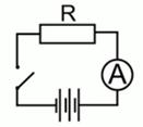
A) For the calculation of the series connection of conductors of task No. 3,4:
B) On the calculation of the parallel connection of conductors of task No. 3
5. Verification work on cards from three options. Solving problems in workbooks. After solving the notebooks, they are submitted for verification to assess knowledge.
6. The result of the lesson. Lesson conclusions. Evaluation of oral responses of students. Homework. P.48,49, questions and assignments for paragraphs.
Exercise 23.
Literature:
textbook grade 8 A. Peryshkin,
The connection of conductors means the connection of resistors - devices made on the basis of the resistance of conductors. In the previous lessons, parallel and serial connections were considered. In this lesson, tasks for a mixed connection of conductors will be considered, that is, when both a serial and a parallel connection are present in the circuit.
To solve problems, first consider the formulas for the relationship of various quantities in parallel and series connections:
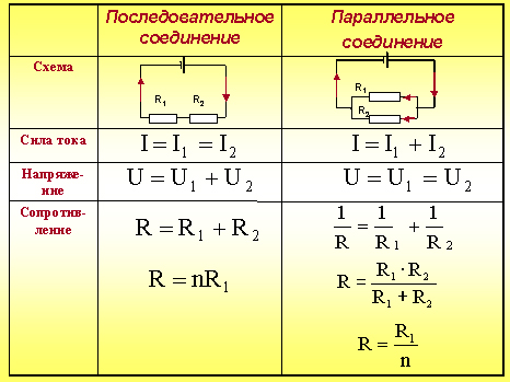
If conductors are connected in series , then the current strength in them is the same and equal to the current strength in the circuit. In this case, the total voltage in the circuit will consist of the sum of the voltages on each conductor. And if we talk about the resistance of this section of the circuit, in which the conductors are connected in series, then it is equal to the sum of the resistances of the conductors.
In a parallel connection, things are different. The current in each branch of this circuit will be different, while the total current in the circuit will be calculated as the sum of the currents in the conductors. The voltage across conductors connected in series will be the same. The total resistance of this section of the circuit, the so-called "equivalent resistance" R, will be calculated using the following formula:.
It is also worth noting that a parallel connection is usually used when turning on household appliances, and a series connection is used in order to create a long unbranched circuit.
Consider the following problem. The circuit section consists of two series-connected resistances, each of which is equal to 1 ohm. To these two resistors, another resistance is connected in parallel, the value of which is 2 ohms. This entire circuit is connected to a current source, which creates a voltage of 2.4 V at the ends of this connection. It is necessary to determine the current strength in the entire electrical circuit (Fig. 1).
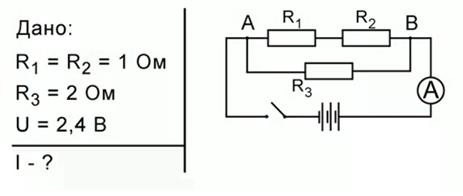
Rice. 1. Conditions and drawing of problem No. 1
As you can see, the resistors R1 and R2 are connected in series, the resistor R3 is connected in parallel to them. The source gives a voltage of 2.4 V, respectively, in section AB, the voltage will also be 2.4 V. The current strength that you want to find is the current flowing through the ammeter A.
Such a connection of conductors is called unbranched. The industry usually makes a set of resistors with well-defined resistances, but any number of different resistances may be needed for experimentation. Then, using such circuits, you can create the desired resistance for the experiment or device.
Next, you need to determine the equivalent resistance of the unbranched part. First, let's see what the resistance R' of the section of the circuit AB, which contains only resistors R1 and R2, is equal to. They are connected in series, then R′=R1+R2=2 [Ohm]. Now you can redraw the electrical circuit by replacing the resistances R1 and R2 with their equivalent resistance R' (Fig. 2).
Rice. 2. First replacement with equivalent resistance
Now we can say that the section AB includes not three, but two resistances: R3 and R '. These two resistances are connected in parallel, respectively, you can find the total resistance of the electrical circuit by the formula. Expressing R and substituting the values, we get:
![]()
It is worth noting that the resistances were connected, but the total resistance was still equal to 1 ohm. Now the electrical circuit can be replaced by the following (Fig. 3):
Rice. 3. Second replacement with equivalent resistance
On fig. 3 resistance R = 1 ohm is called the equivalent resistance, since three resistances have been replaced by one. To calculate the current strength in the circuit, you must use Ohm's law for the circuit section:. The voltage on the resistance R is the voltage on the section AB (Fig. 1), which, in turn, is 2.4. Then. This will be the value of the current in the electrical circuit, which will show the ammeter.
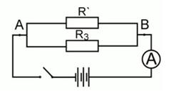
Now consider a problem in which there will also be three resistances, but they will be connected in a different way (Fig. 4):
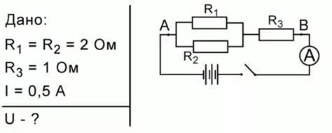
Rice. 4. Condition of problem No. 2
Two resistances R1 and R2 are connected in parallel (R1=R2=2 ohms), they are also connected in series with resistance R3=1 ohm. The ammeter shows the current strength in the circuit, equal to I \u003d 0.5 A. It is required to determine the voltage at the ends of the section of this circuit, that is, in section AB.
First, let's determine the resistance of the circuit section containing the resistances R1 and R2. These two resistances are connected in parallel, which means that their equivalent resistance R' can be found from the formula. Substituting the values, we get:
![]()
Now we can say that the circuit includes only two resistances: R'and R3, which are connected in series.
![]()
Rice. 5. Replacing a Parallel Connection with an Equivalent Resistance
The task is to determine the voltage. For this, a device called a voltmeter is used. It is connected in parallel to the circuit. And consider a section of the circuit in which all three resistances have already been replaced by an equivalent one.
Rice. 6. Inclusion of a voltmeter in the circuit
The voltmeter is included in the place corresponding to section AB in fig. 4. Accordingly, it measures the voltage in this section of the circuit. To find the values of this voltage, you must first find the equivalent resistance. The resistances R’ and R3 are connected in series (Fig. 5), which means that the equivalent resistance is determined by the formula:
Now, from Ohm's law for a section of the circuit, you can find the voltage:
![]()
This means that the voltmeter will have to show a voltage value of 1 V.
The lesson examined the connections of only three resistances, when they were in series, a third is connected in parallel to them, or when two are connected in parallel, and a third resistance is connected in series to them. But real schemes are much more complicated. They contain a huge number of different elements, resistances, so there are quite complex methods for calculating electrical circuits.
For the first time, scientists were puzzled by the calculations of such complex electrical circuits around the 19th century, and new rules appeared that are still used today. The German scientist Kirchhoff developed the ability to calculate electrical complex circuits, so the rules that are used for complex circuits are called "Kirchhoff's rules".
In the following lessons, the concept of power and work of current strength will be considered.
Bibliography
- Gendenstein L.E., Kaidalov A.B., Kozhevnikov V.B. / Ed. Orlova V.A., Roizena I.I. Physics 8. - M.: Mnemosyne.
- Peryshkin A.V. Physics 8. - M.: Bustard, 2010.
- Fadeeva A.A., Zasov A.V., Kiselev D.F. Physics 8. - M.: Enlightenment.
- Festival.1september.ru ().
- Electroandi.ru ().
- Bocharova.ucoz.ru ().
Homework
- Page 117: Problems No. 4, 5. Peryshkin A.V. Physics 8. - M.: Bustard, 2010.
- In which case will the equivalent resistance be greater: if three conductors with resistances of 1 ohm each are connected in parallel or in series?
- Two resistances R1=1 ohm and R2= 2 ohms are connected in series, a 3 ohm resistance is connected to them in parallel. What is the equivalent resistance?
- How many different circuits can be made from three 1 ohm resistors so that their equivalent resistances are different?
« Physics - Grade 10 "
When solving problems on the application of Ohm's law, it must be taken into account that when the conductors are connected in series, the current strength in all conductors is the same, and when they are connected in parallel, the voltage is the same on all conductors.
Task 1.
Parallel to the ammeter, which has a resistance R a \u003d 0.5 Ohm, a copper wire with a length of l \u003d 0.4 m and a diameter of d \u003d 0.001 m is connected. The specific resistance of copper is ρ \u003d 1.7 10 -8 Ohm m. Determine the total current in the circuit if the ammeter shows the current strength I a \u003d 0.2 A.
Solution.
Since the ammeter and wire are connected in parallel, the voltage across the ammeter is equal to the voltage across the wire:
I a R a \u003d I n R n.
Determine the resistance of the wire:
Then ![]()
Total current in the circuit
Task 2.
In figure 15.7, all the resistances of the resistors are equal to R. Determine the equivalent resistance of the circuit.
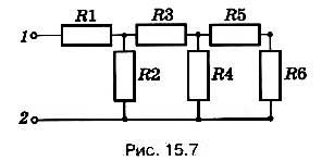
What is the total current in the circuit if voltage U is applied to terminals 1, 2?
It is difficult to determine whether resistors R1 and R3 are connected in series or in parallel. In such circuits, you should always look for resistors whose connections are obvious. So, it is obvious that the resistors 7?5 and R6 are connected in series. So R 5,6 = R 5 + R 6 = 2R. An equivalent resistor with a resistance of R 5.6 is connected in parallel with a resistor R 4. Hence,
An equivalent resistor with a resistance R 4-6, in turn, is connected in series with a resistor R 3:
R 3-6 \u003d R 3 + R 4-6 \u003d R + (2/3) R \u003d (5/3) R,
and an equivalent resistor with a resistance R 3-6 - in parallel with the resistor R 2:
Finally, the equivalent resistor R 2-6 is connected in series with resistor R 1 , so that
R equiv \u003d R 2-b + R \u003d (5/8) R + R \u003d (13/8) R.
It follows from Ohm's law that the current
Task 3.
Ten light bulbs with the same resistance r are connected in parallel to a section of the circuit with a voltage U through a resistor with a resistance R.
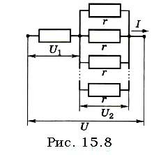
Determine the voltage at each light bulb.
Solution.
Let's draw a circuit diagram (Fig. 15.8). Obviously, the voltage on each light bulb will be the same, since they are connected in parallel.
A resistor with resistance R and a circuit section with light bulbs are connected in series,
therefore U \u003d U 1 + U 2 \u003d IR + IR equiv.
Let's write Ohm's law for each section of the circuit:
from where or
Solving this equation for U 2,
we get ![]()
Let's find the equivalent resistance of the circuit section with light bulbs from the ratio