A detailed description of how to use the multimeter correctly. How to use a multimeter: we take measurements.
Any electrician, whether beginner or professional, should be able to use this kind of tester as a multimeter. This device is used for a wide range of electrical measurements, because thanks to one small box, you can detect a malfunction regarding electrical conductors on any device, as well as detect a break in closed wiring. How to use a multimeter correctly, you will learn from this article.
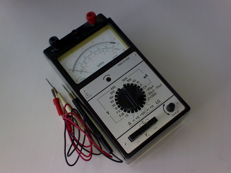
The development of measuring instruments began immediately after the advent of electricity, but all models were very large and could only measure one indicator. The first tester that could accommodate several indicators for measuring current, resistance and voltage was created by Soviet scientists in 1952. It was named TT-1 and since then has experienced numerous improvements (TT-2, TT-3, TL-4, TTs, etc.).
How a multimeter works
Each device is equipped with two leads with a black wire and a red one, respectively. Additionally, there are from 2 to 4 nests. The red wire is potential and serves for measurement, and the black one is responsible for the total mass. The mass wire at the end has a clip (crocodile) for easy connection to the mass of the measured device. The red output is inserted into the connectors marked with such symbols as: ft, +, V, ampere (A), milliamp (mA), 10A, 20A.
If you look at the switches, you can configure the following options:
- 10V, 50V, 250V, 1000V is the choice of AC voltage and direct current(ACV and DCV);
- 5mA, 50mA, 500mA - current strength;
- X1K, X10, X100 in analog and 200Ohm, 2kOhm, 20kOhm, 200kOhm, 2mOhm for digital - this is the multiplication of resistance by a given number of times;
Digital multimeters have additional features: sound continuity of diodes, temperature sensor, frequency meter, measurement of capacitor capacitance, checking transistor tracks.
Important! When you want to measure some indicators, but do not know the exact power of the device, set the maximum values, lowering them by one division to adequate measurement figures. Thus, you will never burn the tester.
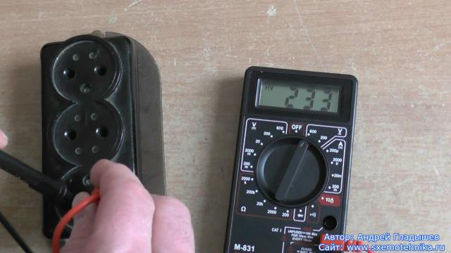
First you need to insert the probes into the appropriate sockets, black into the socket marked COM, and red into the socket marked V, mA. The third socket says 10ADC, but this is for measuring high currents up to 10A. Next, set the regulator to ACV or DCV. How to measure voltage with a multimeter in an outlet? You need to set ACV 750, because it has alternating current.
For more complex measurements, examples are given below.
How to check resistance with a multimeter
The fixed resistor is an essential element electrical circuit which has constant resistance. Designed for linear processing of current into voltage and vice versa. The method for testing a fixed resistor is described below.
First you need to set the regulator to the resistance multiplier (Ohm). If you are not aware of the desired values of the experimental device, then during the measurement, switch the multiplier until the unit changes to a different number on the screen.
Now you need to take any fixed resistor in order to use it to find out how to measure the resistance with a multimeter.
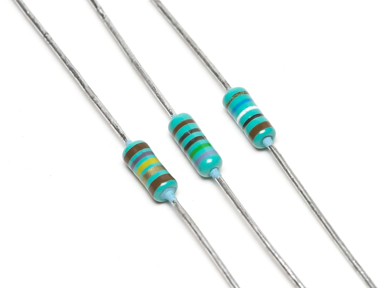
Attach probes to its contacts and you can check the resistance, which should show 82 ohms as indicated on the resistor itself. If the reading is less than 10 percent, then the resistor can be thrown out.
And now take a variable resistor, which is indicated, for example, 47 kOhm.
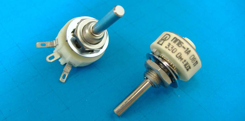
After checking the resistance at the extreme contacts, the indicator should correspond to the marking on the resistor case, if it is less, then it is not a fact that it is a non-working part. Turn the knob on the resistor to the left and check the left with the middle pins. Turn right and check the middle terminal on the right. Add the two results together and if the indicator converges with the first, then such a variable is still useful in the household.
Related article:
The article describes in detail which device is better to choose for the home, taking into account the requirements of the consumer, the characteristics of future tasks and an overview of the measuring instruments market.
How to measure current with a multimeter
The current strength is measured only in the electrical circuit. Sockets cannot be tested for current because you will simply create a short circuit. Force is measured in any AC or DC electrical circuit. The variable power supplies all household appliances, and the constant comes from the batteries.
Having set all the modes suitable for the circuit under test, lean the probes against the initial node, ringing the rest in turn, find out which node is supplied with a current greater than this node, if any, is designed for.
Important! For current measurements with a multimeter, do not forget to use rubber gloves at the time of testing, as the probability of electric shock is very high. Also, do not take measurements in circuits with high humidity.
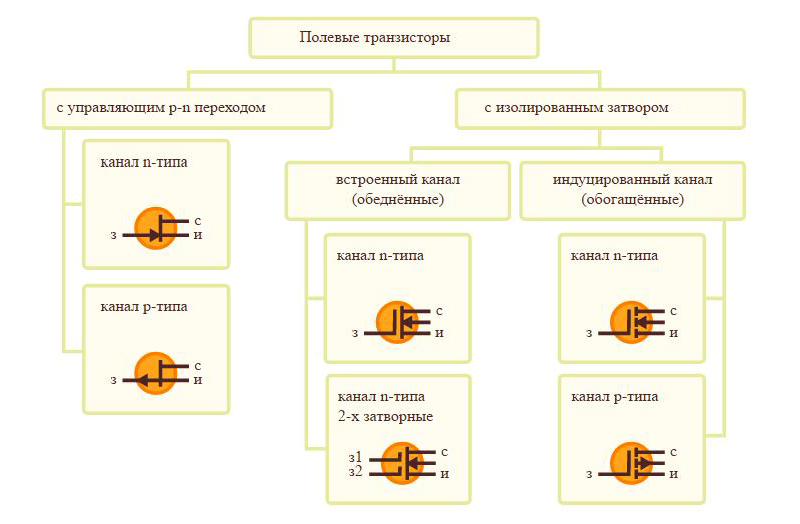
How to test a field effect transistor with a multimeter
Such transistors are divided into n and p types of channels. Since n-types are more common, their verification will be described below.
- How to ring a transistor with a multimeter to the resistance level? Turn on the resistance measurement on the device and set the limit to 2kΩ. The probes must be leaned against the source and drain (in the diagram they are indicated by the corresponding letters and, c)
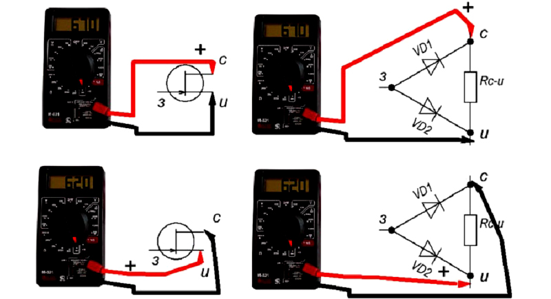
When changing the polarity, the indicators should have almost equal numbers.
- Removal of measurements source - shutter. The multimeter must be switched to the diode continuity mode. The red wire is connected to the gate (marked with the letter h in the figure), and the black wire to the source. There should be a drop in indicators at the open transition to a figure of 650 mV (+/-).
When changing the polarity, the value must be infinite, that is, equal to 1.
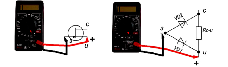
- Now check the stock - shutter indicators. All manipulations are carried out as in paragraph 2, only the black probe is connected to the drain. The scores should be the same.
Polarity reversal is similar to point 2.
When you complete all the points and the indicators are similar to those in the diagrams above, the transistor can be considered serviceable.
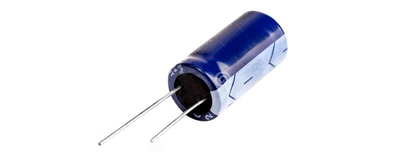
Method for testing capacitors with a multimeter
All capacitors are divided into polar and non-polar. Polar capacitors are electrolytic, all other modifications are non-polar devices.
A feature of polar models is the way they are soldered to the board. The positive contact is soldered to the plus of the board, and the negative to the minus. Non-polar can be soldered as you like.
As for safety in working with polar capacitors, if the contacts are incorrectly soldered, it can explode (applies to Soviet models), imported ones have special creases on the top of the case, which, in the event of an explosion, will simply open and suppress the accident.
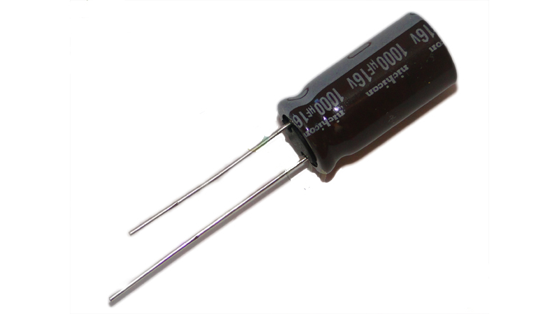
Speaking about the properties of the capacitor, it should be noted that it constantly passes only alternating current through itself, the direct current passes only for a few seconds (until it is charged), and then it does not pass. To measure the capacitances of capacitors with a multimeter, they must have a capacitance of 0.25 microfarads. Otherwise, you will need an instrument such as an LC meter.
To start measuring, you need to find out where the negative contact of the capacitor is. This is done simply. Manufacturers put a black check mark on the case, which indicates that there is a minus under it.
Take the object to be tested, and with the help of any metal conductor, close the contacts between each other. That's it, the capacitor is discharged. Now take a multimeter and set the dialing mode. Attach the probes to the contacts. The first thing that the device will show is the minimum value, but the tester has a battery that produces a constant current. It turns out that if you continue to hold the probes on the contacts, then the capacitor will be charged and the indicators will continue to grow indefinitely (1 on the display).
If, when you first connect the multimeter to the device, the resistance is zero or immediately shows one, then this capacitor is not working.
Note! There is another way to check. It is necessary to charge the capacitor from an energy source that corresponds to its power, and then, with the help of metal, close its contacts. If a spark appears at the moment of contact, then the capacitor is in working condition.
Calling methods
There are many examples of power failures, to identify which, you need to use dialing. A break in the line can be both in the wire that feeds the household appliance, and in hidden wiring. You can identify the gap using a multimeter by doing simple steps.
- As an example, a cable from a computer monitor, which has three cores, will be checked.
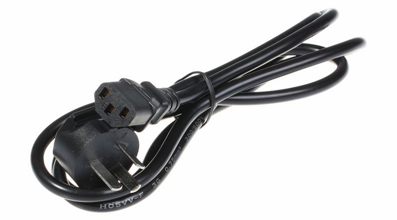
Set the resistance measurement mode on the multimeter. Then you lean the first probe against one of the contacts of the plug, and put the second one in turn into each slot of the connector on the other end of the wire. The multimeter display should show a figure of about 2.5 ohms, if the value reaches 10 ohms, then this core contains a break. The connector that shows zero does not belong to the powered contact on the plug.
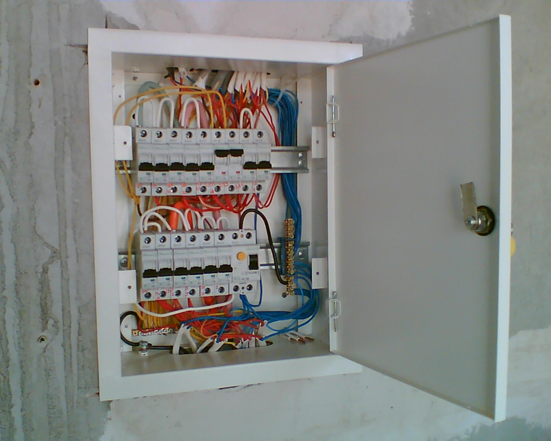
- Method for checking hidden wiring. Set the multimeter to the diode continuity function. Now you need to go to the switchboard with machine guns. Using an indicator screwdriver, you need to find the phase by first turning on all the machines. Mark the found phase with electrical tape.
Next, you need to define zero. Set the device to check the voltage, and the regulator to 750V. Lean one probe to the phase, and with the second, ring all the remaining cables until one of them gives out an indicator of 220. Also mark the found wire. In this way, you should find all the remaining pairs.
To ring each conductor, it must be disconnected from the power supply (disconnected from the machine). Set the multimeter to dial and connect the probes together. You will see zeros on the display. Having opened the probes, touch them to a pair of conductor. A whole wire will show zero resistance. By ringing the remaining pairs of wires, you can determine on which line the break occurred.
Note! For a full-fledged reading of indicators, you need to press the probe tips well against the contacts being checked.
Tips & Tricks
- When using an analog (pointer) multimeter, it must be placed on a flat surface and any vibrations in the vicinity of the instrument should be avoided. Otherwise, its indicators will give an error.
- Never leave the measuring device switched on, its battery will quickly run out. If the multimeter does not have an OFF button, then you need to set the position for measuring voltage.
- Try not to touch the ends of the probes with your hands, if they become dirty, then there will be an error in the indicators.
- Before performing any actions with the multimeter, calculate each step without haste. If you make a mistake, your measurements may remain incomplete due to a breakdown of the device.
General conclusion
Now you know how to use the multimeter correctly, but never neglect its settings, in accordance with setting it to the desired indicators. With the help of such devices, you can easily make friends with electricity. Good luck with your electrical troubleshooting.
Modern cars are not complete without electronics; moreover, they are simply crammed with electrical circuits and devices. In order to quickly diagnose malfunctions in the electrical circuits of a car, you will at least need a device such as a multimeter.
In this article, we will consider the most common modifications and analyze in detail how to use a multimeter for dummies, i.e. for those who have never held this device in their hands, but would like to learn.
Main connectors and functions of the multimeter
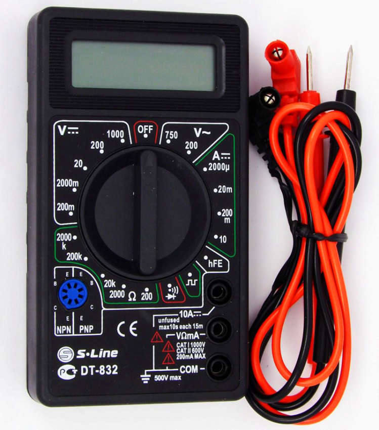
In order to better understand what is at stake, we will give a visual photo of the multimeter and analyze the modes and connectors.
Let's start with the connectors where to connect the wires. The black wire is connected to a connector called COM (COMMON, which means common in translation). The black wire is always connected only to this connector, unlike the red one, which in most cases has 2 connectors for connection:
- VRmA connector - used to measure voltage, resistance and currents above 10 A (Amps);
- 10A connector - used to measure currents up to 10 A.
Functions and ranges of the multimeter
Around the central pointer you can see the ranges separated by white outlines, let's analyze each of them:
- DCV - (DC - direct current, V - voltage) using this range, DC voltage is measured. Volts and millivolts are indicated on the scales;
- ACV - (AC - alternating current, V - voltage) voltage is measured accordingly alternating current;
- DCA - (DC - direct current, A - Amps) measurement of direct current (the range from 200 microamps to 200 milliamps is indicated on the device);
- 10A - a separate measurement range for a larger direct current, for this you need to rearrange the red wire to the top connector;
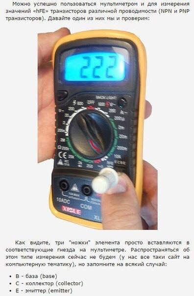
- hFE - transistor test mode;
- Omega - resistance measurement range.
Battery DC voltage measurement
Let's give a good example of how to use a multimeter, namely, we will measure the DC voltage of a conventional battery.
Since we initially know that the DC voltage in the battery is about 1.5 V, we can immediately set the switch to 20 V.
Important! In case you do not know the DC voltage in the measured instrument or device, it is always necessary to set the switch to the maximum value of the desired range and, as necessary, reduce it to reduce the error.
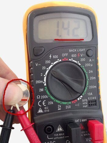
We turned on the desired mode, go directly to the measurement, apply the red probe to the positive side of the battery, and the black probe to the negative side - we look at the result on the screen (should show a result of 1.4-1.6 V, depending on the state of the battery).
Features of measuring AC voltage
Let's analyze in detail what you need to pay attention to if you measure AC voltage.
Before work, be sure to check which connectors the wires are inserted into, because if, when measuring alternating current, the red wire is inserted into the current measurement connector (10 A connector), a short circuit will occur, which is highly undesirable.
Again, in case you don't know the AC voltage range, then set the switch to the maximum position.
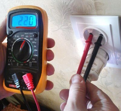
For example, in domestic conditions, we know that the voltage in sockets and electrical appliances is approximately 220 V, respectively, 500 V from the ACV range can be safely set on the device.
How to measure current leakage in a car with a multimeter
Consider how to measure the leakage current in a car using a multimeter. First turn off all electronics and remove the key from the ignition. Next, you need to throw off the negative terminal from the battery (leave the positive terminal unchanged). We set the multimeter to the mode of measuring direct current 10 A. Do not forget to rearrange the red wire to the appropriate connector (upper, corresponding to 10 A). We connect one probe to the terminal on the disconnected wire, and the second directly to the minus of the battery.
After waiting a bit until the values stop jumping, you will see the required leakage current value in your car.
What leakage value is acceptable
- The minimum allowable value is 15 mA;
- The maximum value of current leakage in a car is 70 mA.
If your maximum value is exceeded, then you need to proceed to the search for a leak. Leaks can be created by any electrical device in the vehicle.
The basic principle of the search is to alternately pull out the fuses and verify the leakage values. If you removed the fuse and the leakage value on the device has not changed, then everything is fine with the device for which this fuse is responsible. And if, after removal, the value began to jump, then something is wrong with the corresponding device.
› How to use a multimeter.A multimeter is also often referred to as a "multi-tester" because it is designed to take a fairly wide range of indicators: measuring constant and AC voltage, resistance and current strength. Many multimeters also have the ability to measure the gain of transistors and have a special mode for testing diodes, continuity for a short circuit, etc. In a word - "multi" (for many) "tester".
Expensive models like measuring devices include additional functions: temperature measurement (using a thermocouple probe), coil inductance, capacitor capacitance.
We will learn how to use a multimeter using the example of a Chinese-made budget device worth $ 10-15 "XL830L"
Its delivery set includes a set of simple "probes", with the help of which measurements are made. They, if necessary, can be replaced with better or more comfortable ones.
👉 Note: be ready to immediately fix the entry points of both wires into the hollow plastic holder tubes with something (adhesive tape, electrical tape). The fact is that the conductors in the tubes are not rigidly fixed and when turning and bending the "probe" they can easily come off (due to the extremely flimsy solder) near the base of the measuring tip.
Before you start using the multimeter in full, let's take a closer look at our digital tester.
In its upper part we see a seven-segment digital display that can display up to four digits (9999 is the maximum value). When the battery is discharged, a corresponding inscription appears on it: “bat”.
There are two buttons below the board. On the left is the “Hold” button - holding the readings of the last value (so as not to keep it in memory when copying to a notepad). And on the right - "Back Light" - the backlight of the screen in blue (when measured in poor lighting conditions). On the back of the multimeter case there is a folding leg-stand (for convenient placement of the tester on the table).
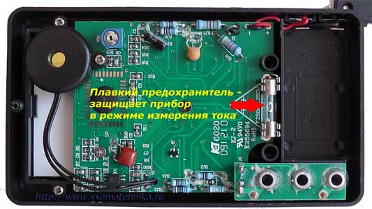
The digital multimeter is powered by a 9-volt Krona battery. True, to get to it we will have to remove the rubber protective cover and the back cover of the tester.
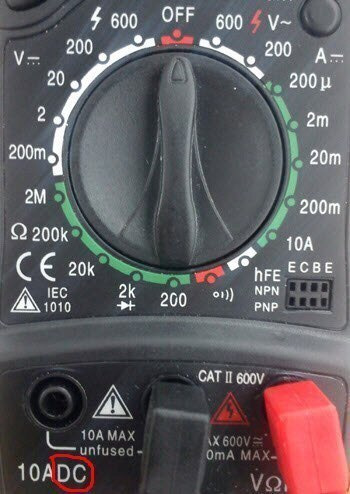
Circled in red at the bottom is our battery, and at the top is a fuse, which (I hope) will protect our meter from failure in the event of an overload.
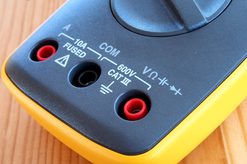
So, before you start using the multimeter, you must correctly connect the measuring "probes" to it. General principle here is the next one:
The black wire (it is called differently: common, com, common, ground) is a minus. We connect it to the corresponding socket of the multitester labeled "COM". Red - in the nest to the right of him, this is our "plus".
The remaining free socket on the left is for measuring direct current with a limit of up to 10 amperes (high currents) and - without a fuse, as evidenced by the warning inscription "unfused". So be careful - do not burn the device.
Also note the warning sign (red triangle). Under it is written: MAX 600V. This is the maximum allowable voltage measurement limit for this multimeter (600 Volts).
🚨 Warning! Remember the following rule: if the measured values of voltage (Volts) or current strength (Amperes) are not known in advance, then to prevent the multitester from failing, set its switch to the maximum possible measurement limit. And only after that (if the readings are too small or not accurate), switch the device to a limit below the current one.

Now, in fact, - how to use a multimeter and how to switch these very "limits"?
It is necessary to work with a multimeter using a circular switch with a pointing arrow. By default, it is set to the “OFF” position (the device is turned off). We can rotate the arrow in any direction and thus "tell" the multitester what exactly we want to measure or - with what maximum limit we will work.
There is one very important point here! Working with a digital multimeter, we are able to measure the values of both AC and DC current and voltage. Now in industry and everyday life, the vast majority uses alternating current. It is he who "flows" through high-voltage lines of wires from generators of power plants to our homes, "lights" our lighting lamps and "feeds" various household electrical appliances.
Alternating current, compared to direct current, is much easier to convert (using transformers) into a current of a different (we need) voltage. For example: 10,000 volts can be easily converted into 220 and completely calmly directed to the needs of a residential building. Alternating current (compared to direct current) is also much easier to "extract" on an industrial scale and transmit it (with less loss) over long distances.
It is necessary to use a multimeter, given all of the above. Therefore, memorize the following abbreviations:
DCV = DC Voltage - (eng. Direct Current Voltage) - constant voltage
ACV \u003d AC Voltage - (eng. Alternating Current Voltage) - alternating voltage
DCA - (eng. Direct Current Amperage) - current strength of direct voltage (in amperes)
ACA - (eng. Alternating Current Amperage) - current strength of alternating voltage (in amperes)
Now, - we can learn to use the multimeter further. Take a closer look at the dial of your meter and you will definitely see that it is divided strictly into two parts: one for measuring DC and the second for AC voltages.
See the two letters "DC" in the lower left corner in the photo above? This means that to the left (relative to the “OFF” position) we will work with a multimeter, measuring constant values of voltage and current. Accordingly, the right side of the multitester is responsible for measuring AC current.
Now I suggest you immediately consolidate the acquired knowledge in practice. Let's show an example of using a multimeter to measure the capacity of a conventional CR 2032 bios battery with a nominal value of 3.3 Volts. Remember our red warning? Always set the limit higher than the measured values. We know that the battery has 3.3V and this is a direct current. Accordingly, we set the "limit" of measurements on the DC scale to 20 Volts on the circular switch.
Pay attention to the red marked “+” sign on the battery. We apply a "plus" (red probe) to this side of it, and a "ground" (black) to the reverse side.
Note: if you mix up the polarity (to the plus - minus, and to the minus - plus), i.e. - swap "probes" in places - nothing bad will happen, just before the result on the digital display you will see a "minus" sign. The measurement values themselves will remain correct.
So, we used a multimeter and what is the result? Look (photo above) at the digital display of the tester. The numbers "1.42" are displayed there. So our battery now has 1.42 Volts (instead of the prescribed three). With a swing of it - into the trash can! The computer will automatically reset the BIOS settings with such a battery each time it is turned on.
In order to learn how to use a multimeter and work effectively with it, we need to know (remember, write down, memorize, tattoo) the following designations, which we will surely meet on similar meters, regardless of their model.
More advanced samples of multimeters also show the capacitance of the elements - "F" (it is measured in Farads) and the inductance - "L" (calculated in Henry - "H").

The next switch position is 600 volts on the AC scale. It is the best suited for measuring voltage in a household electrical network (current is alternating and the scale value is several times higher than necessary - 220 V.).
The order of the "probes" in the outlet does not matter.
The next position is 200 Volts (you don’t need to measure the voltage in the outlet on it - the multimeter will burn out!). To the right we have the number "200" with the sign "µ" (microampere - one millionth of an ampere). Similar values of quantities can be used in various kinds electrical diagrams.
The next on the scale is "2m" (two milliamps - two thousandths of an ampere). The indicator is found mainly in transistors. Further - "200m" - similarly, but the countdown starts from two hundred milliamps. The next switch position is "10A" ( maximum strength current - ten amperes). This is a territory of high currents, be careful! Here we will need to include the red "probe" into a special socket, indicated in the photo as "10ADC".
Acoustic wave (continuity) line icon for a short circuit. What use is this to us? Let's take a look at an example.
Imagine such a situation (as it turned out - very real) that some of the cables were forgotten to be signed. It turns out the following: on the other wing of the building (at the user's computer socket), we cannot say which cable out of a hundred this particular ending belongs to, and the search for a “happy ending” automatically turns into a separate task
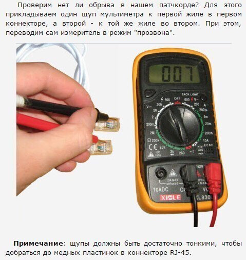
This is where the mode of using the multitester as a "dialer" of the cable for a short circuit will come to our rescue. Since there is a hint in the name itself, we are left with the following - to organize this very short circuit (short circuit).
Share: Follow authorIf you were wondering " How to use a multimeter?”, then at least you already know what electricity and tension. If not, then I suggest that you familiarize yourself with the first chapters of my electronics textbook.
So what is a multimeter?
Multimeter - it is a universal combined measuring device that combines the functions of several measuring devices, that is, it can measure a whole range of electrical quantities.
The smallest set of multimeter functions is the measurement of voltage, current and resistance. However, modern manufacturers do not stop there, but add to the set of functions, such as measuring the capacitance of capacitors, current frequency, diode continuity (measuring the voltage drop across p-n junction), sound probe, temperature measurement, measurement of some parameters of transistors, built-in low-frequency generator and much more. With such a set of functions of a modern multimeter, the question really arises how to use it after all?
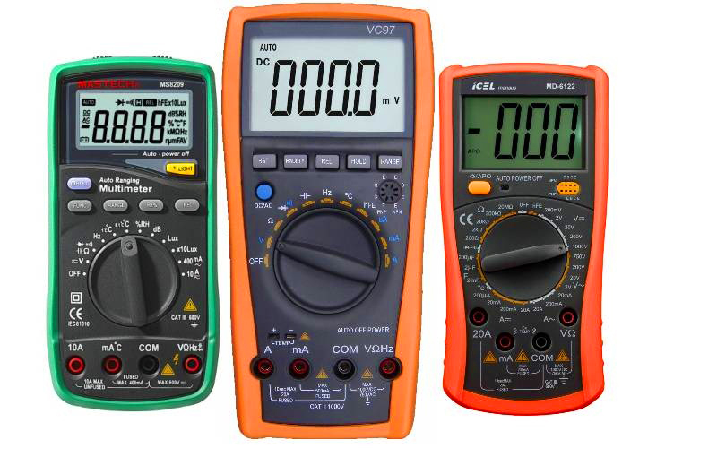
In addition, multimeters are digital and analog . We will not delve into the jungle, I will only say that they outwardly differ in instruments for displaying the measured values. In an analog multimeter, it is an arrow, in a digital one, in the form of a seven-segment indicator. However, we are used to understanding the word multimeter as a digital multimeter. Therefore, in this article I will tell you how to use a digital multimeter.
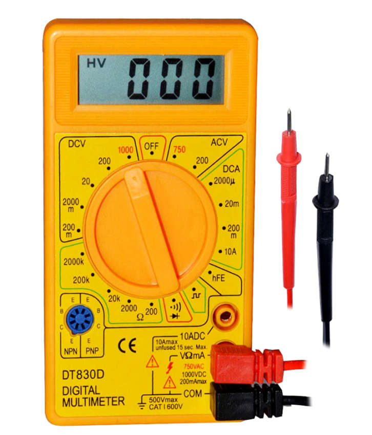
For example, take the widely used multimeters of the series M-830 or DT-830. There are several modifications in this series, their marking differs by the last digit, as well as by the set of functions embedded in this device.
I plan to review the multimeters of this line in one of the next issues of the magazine, so do not forget to subscribe to new issues of the magazine at the end of the article. I will describe how to work with a multimeter using an example device M-831.
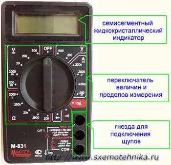
The main functions of the M-831 digital multimeter and the purpose of the instrument controls
Consider carefully outer panel multimeter. Here we see a seven-segment liquid crystal display in the upper part, on which the values we measure will be displayed.
Let us consider in more detail all the designations that are applied in a circle, thereby analyzing the operating modes of the multimeter.
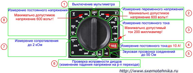
1- turn off the multimeter.
2 - mode for measuring alternating voltage values, has two measurement ranges of 200 and 600 volts.
ACV-AC Voltage- (eng. Alternating Current Voltage) - AC voltage
3 - mode for measuring direct current values in the following ranges: 200 μA, 2000 μA, 20 mA, 200 mA.
Other models of multimeters may use the designation DCA- (eng. Direct Current Amperage) - direct current.
4 - mode for measuring large values of direct current up to 10 amperes.
5 - sound continuity of wires, the sound signal turns on when the resistance of the called section is less than 50 ohms.
6 - checking the health of the diodes, shows the voltage drop at the p-n junction of the diode.
7 - resistance value measurement mode, has five ranges: 200 Ohm, 2000 Ohm, 20 kOhm, 200 kOhm, 2000 kOhm.
8 - DC voltage measurement mode, has five ranges of 200 mV, 2000 mV, 20 V, 200 V and 600 V.
Other models of multimeters may use the designation DCV-DC Voltage- (eng. Direct Current Voltage) - constant pressure.
In the lower right corner of the front panel of the multimeter there are three sockets for connecting the supplied cords with probes.
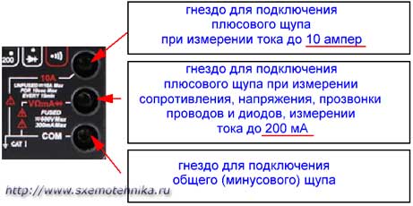
Everything is simple here:
- lower socket for a common (negative) wire in all modes and on all ranges;
- an average socket for a positive wire in all modes and on all ranges except for current measurement mode up to 10 A;
- upper socket for positive wire in current measurement mode up to 10 A.
Be careful, when measuring current more than 200 mA, connect the positive wire only to the top socket!
The multimeter is powered by a 9-volt battery type "Krona" or according to the standard size - 6F22.
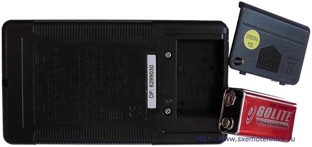
Inside, under the back cover of the multimeter, there is a fuse, usually 250 mA, which protects the device in current measurement mode up to 200 mA.
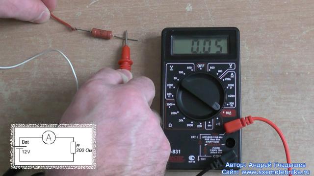
Measurement of electrical quantities with a multimeter
So, it's time to learn how to use a multimeter. We will learn how to measure electrical quantities using the example of the same M-831 multimeter. Let me remind you once again that with this multimeter you can measure direct and alternating voltages up to 600 volts, only direct current values up to 10 amperes and electrical (active) resistance values \u200b\u200bup to 2 megaohms.
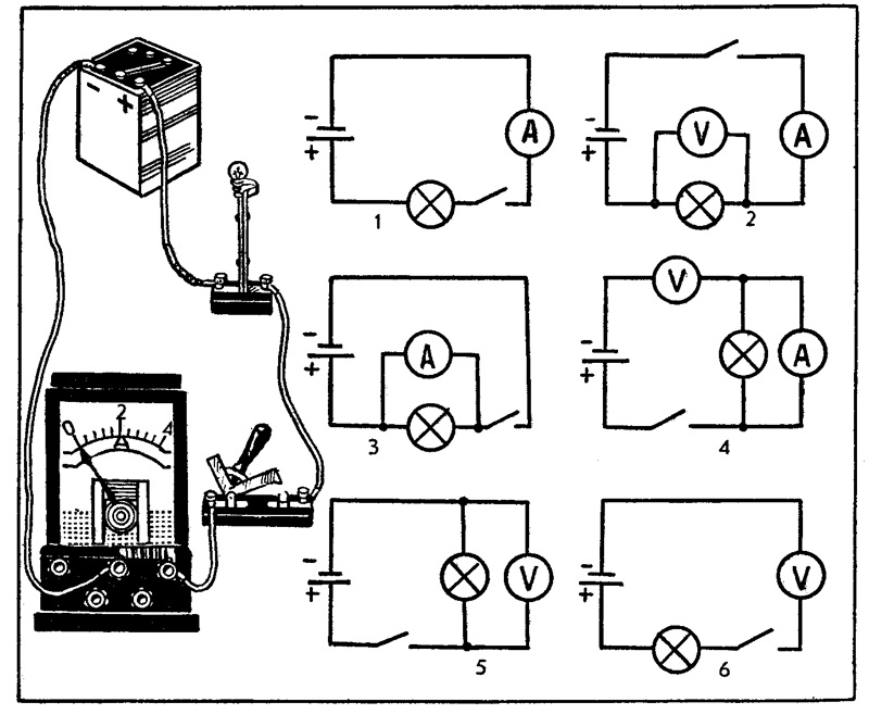
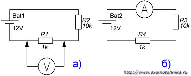
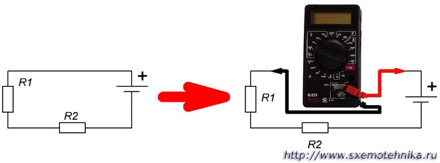
Let me remind you that to measure the voltage on an element (section) of an electrical circuit, the device is switched on in parallel with this element (or section of the circuit).
To measure the current in the circuit, the device is included in the break of the measured circuit (that is, in series with the circuit elements).
How to use a multimeter to measure DC voltage.
Now let me tell you in detail, step by step, how to measure DC voltage with our multimeter.
The first thing to do is to choose the type of voltage to be measured and the measurement limit. To measure DC voltage, the multimeter has a range of DC voltage values that are set using the limit switch.
To set the measurement limit, we first determine approximately what voltage value we want to measure. Here you need to act according to the situation, if you measure the voltage of the batteries (batteries, accumulators), then look for the inscriptions on the elements, if you measure the voltage in various electrical circuits, then I think since you have “climbed” there, then you already know how use a multimeter!
Suppose we need to measure the constant voltage on the battery from some electronic device(I'll take the camcorder battery).
1. We carefully study the inscriptions on the battery, we see that the battery voltage is 7.4 volts.
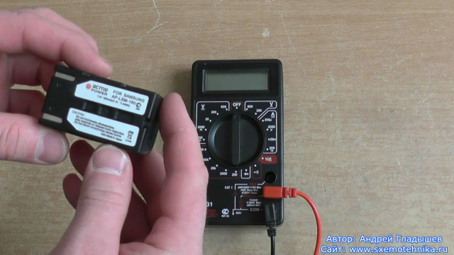
2. Set the measurement limit greater than this voltage, but preferably close to this value, then the measurements will be more accurate.
For our example, the measurement limit is 20 volts.
Nevertheless, when measuring voltage, for example, in circuits, I advise you to set a limit greater than the supply voltage of the circuit, so as not to cause the device to fail.
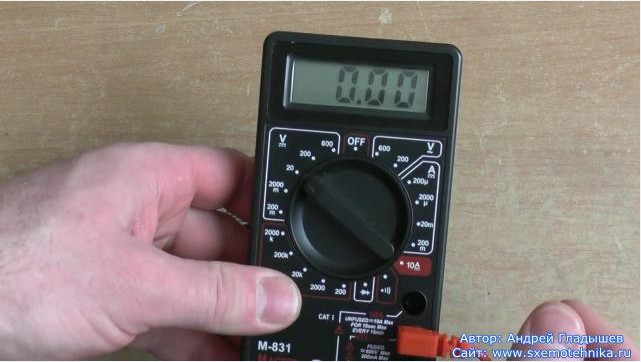
3. We connect the multimeter to the battery terminals (or parallel to the area where you measure the voltage).
- black probe one end to the COM socket of the multimeter, the other to the minus of the measured voltage source;
- red probe to the VΩmA socket and to the plus of the measured voltage source.
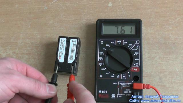
4. We remove the value of the constant voltage from the LCD indicator.
Note: if you do not know the approximate value of the measured voltage value, then the measurement must be started by setting the largest limit, that is, for the M-831 - 600 volts, and successively approaching the limit closest to the measured voltage value.
How to use a multimeter when measuring AC voltage.
Measurement of AC voltage is carried out according to the same principle as the measurement of DC voltage.
Switch the instrument to AC voltage measurement mode by selecting the appropriate AC voltage measurement limit.
How to use a multimeter when measuring DC current.
Let me remind you that the 830 series devices measure only DC values, so if you need to measure current in an AC circuit, then look for another device.
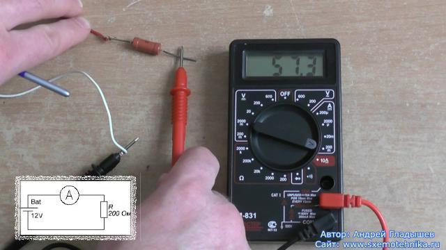
A multimeter for measuring current is connected to the break of the measured circuit.
Again, it is necessary to determine the maximum possible current value in the measured circuit.
If the current values are less than 200 mA, then select the appropriate measurement limit, connect the red probe to the socket VΩmA and turn on the multimeter to open the circuit.
For measuring current in the range 200mA-10A, connect the red probe to the socket 10A .
It is advisable to connect the multimeter in the current measurement mode to the circuit with the voltage removed in the circuit, and at the limit of 10A this is a mandatory operation, since at high currents this is not at all safe.
And the last nuance: in the characteristics of devices from some manufacturers, it is not recommended to turn on the multimeter to measure the current at the limit of 10 A for more than 15 seconds.
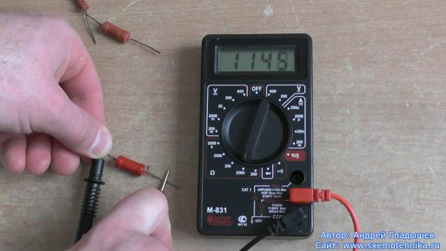
How to use a multimeter to measure resistance.
To measure resistance with a multimeter, the latter must be switched to one of the five limits for measuring resistance.
Moreover, the rules for choosing the measurement limit are as follows:
1. If you know in advance the value of the measured resistance (for example, in the case of checking the resistor for “good” or “faulty”), then the measurement limit is chosen greater than the value of the measured resistance, but as close as possible to it. Only in this case will you minimize the error in measuring resistance.
2. If you do not know the value of the measured resistance in advance, then you need to set the maximum measurement limit (for the M-831 it is 2000 kOhm) and by changing the limits consistently approach the measured resistance value.
Note: if “1” is displayed on the multimeter screen, then the value of the measured resistance is greater than the set measurement limit, in this case it is necessary to switch the limit in the direction of its increase.
To measure resistance, simply connect the probes of the device to the element whose resistance you want to measure and take readings from the indicator of the device.
Watch this video and learn not only how to measure current, voltage and resistance, but also how to ring wires and check diodes with a multimeter!


