A simple homemade voltmeter. Simple Modular AC Voltmeter on PIC16F676
N. OSTROUKHOV, Surgut
The article describes an AC voltmeter. It is assembled on a microcontroller and can be used as a stand-alone measuring device or as a built-in voltmeter in a low-frequency generator.
The proposed voltmeter is designed to measure AC voltage sinusoidal frequency from 1 Hz to 800 kHz. The measured voltage interval is 0...3 V (or 0...30 V with an external voltage divider 1:10). The measurement result is displayed on a four-digit LED indicator. The measurement accuracy is determined by the parameters of the ADC built into the microcontroller and the reference voltage source and is equal to 2 mV (for the interval 0...3 V). The voltmeter is powered by a stabilized voltage source of 5 V and consumes a current of 40 ... 65 mA, depending on the indicator used and the brightness of its glow. The current consumed from the built-in polarity converter does not exceed 5 mA.
The structure of the device (see the diagram in Fig. 1) includes an AC-to-DC converter, a DC buffer amplifier, digital voltmeter and a polarity converter of the supply voltage. The AC to DC converter is assembled on a comparator DA1, a pulse generator on the elements DD1.1-DD1.4 and a switching transistor VT1. Let's take a closer look at his work. Assume that there is no signal at the input of the device. Then the voltage at the inverting input of the DA1 comparator is zero, and at the non-inverting input it is determined by the voltage divider R19R22 and, at the ratings indicated in the diagram, is about -80 mV. At the output of the comparator in this case, there is a low level that allows the pulse generator to work. The peculiarity of the generator is that with each voltage drop at the output of the comparator DA1, one pulse is formed at the generator output (pin 8 of the DD1.2 element). If by the time it falls, the output state of the comparator does not change, the next pulse will be generated, and so on.
The duration of the pulses depends on the ratings of the elements R16, C5 and is approximately 0.5 μs. At a low voltage level at the output of the element DD1.2, the transistor VT1 opens. The values of the resistors R17, R18 and R20 are chosen so that a current of 10 mA flows through the open transistor, which charges the capacitors C8 and C11. During the duration of each pulse, these capacitors are charged by fractions of a millivolt. In steady state, the voltage on them will increase from -80 mV to zero, the generator pulse frequency will decrease and the collector current pulses of transistor VT1 will only compensate for the slow discharge of capacitor C11 through resistor R22. Thus, due to the small initial negative offset, even in the absence of an input signal, the converter operates normally. When an input AC voltage is applied, due to a change in the pulse repetition rate of the generator, the voltage across the capacitor C11 changes in accordance with the amplitude of the input signal. LPF R21C12 smoothes output voltage converter. It should be noted that only the positive half-wave of the input voltage is actually converted, so if it is asymmetric about zero, an additional error will occur.
The buffer amplifier with a transfer coefficient of 1.2 is assembled on the op-amp DA3. The VD1 diode connected to its output protects the microcontroller inputs from negative polarity voltage. From the output of the op-amp DA3 through resistive voltage dividers R1R2R3 and R4R5, a constant voltage is supplied to the lines PC0 and PC1 of the microcontroller DD2, which are configured as ADC inputs. Capacitors C1 and C2 additionally suppress interference and interference. The actual digital voltmeter is assembled on a DD2 microcontroller, which uses a built-in 10-bit ADC and an internal reference voltage source of 1.1 V.
The program for the microcontroller was written using the BASCOM-AVR environment and allows the use of three- or four-digit digital LED indicators with a common anode or common cathode and allows you to display the effective (for a sinusoidal signal) or amplitude value of the input signal voltage, as well as change the brightness of the indicator glow Logic level The signal on the PC3 line specifies the type of indicator used - with a common anode (low) or with a common cathode (high), and on the PC4 line - the number of its digits, four for low and three for high. The program at the beginning of work once reads the signal levels on these lines and configures the microcontroller to work with the corresponding indicator. For a four-digit indicator, the measurement result is displayed as X.XXX (V), for a three-digit indicator - XXX (mV) up to 1 V and X.XX (V), if the voltage is more than 1 V. When using a three-digit indicator, the outputs of its digits are connected as the outputs of three senior digits of the four-digit in fig. 1.
The signal level on the PC2 line controls the multiplication of the measurement result by 10, which is necessary when using an external 1:10 voltage divider. At a low level, the result is not multiplied. The signal on the PB6 line controls the brightness of the indicator; at a high level, it decreases. The change in brightness occurs as a result of a change in the ratio between the glow time and the extinguishing time of the indicator within each measurement cycle. With the constants set in the program, the brightness changes by about half. The effective value of the input voltage is displayed when a high level is applied to the PB7 line and the amplitude value is low. The program analyzes the signal levels on the lines PC2, PB6 and PB7 in each measurement cycle, and therefore they can be changed at any time, for which it is convenient to use switches. The duration of one measurement cycle is 1.1 s. During this time, the ADC performs about 1100 readings, the maximum is selected from them and multiplied, if necessary, by the desired coefficient.
For a constant measured voltage, one measurement for the entire cycle would be enough, and for an alternating voltage with a frequency of less than 500 Hz, the voltage on the capacitors C8. C11 changes markedly during the cycle. Therefore, 1100 measurements with an interval of 1 ms allow fixing the maximum value for the period. The supply voltage polarity converter is assembled on a DA2 chip according to a standard scheme. Its output voltage -5 V feeds the comparator DA1 and op amp DA3. The XP2 connector is intended for in-hardware programming of the microcontroller.
The voltmeter uses fixed resistors C2-23, MLT, trimmers - Bourns series 3296, oxide capacitors - imported, the rest - K10-17. The 74AC00 microcircuit can be replaced with KR555LAZ, the KT361G transistor with any of the KT3107 series. We can replace the 1N5818 diode with any germanium or Schottky diode with a permissible forward current of at least 50 mA. The replacement for the ICL7660 chip is unknown to the author, but the +5/-5 V voltage polarity converter can be assembled according to one of the circuits published in the Radio magazine. In addition, the converter can be completely eliminated by using a bipolar stabilized power supply. Particular attention should be paid to the choice of comparator, since the operating frequency range depends on it. The choice of the LM319 comparator (analogues KA319, LT319) is due to two criteria - the required speed and availability. Comparators LM306, LM361, LM710 are faster, but it turned out to be more difficult to obtain them, and besides, they are more expensive. More accessible are LM311 (domestic analogue of KR554SAZ) and LM393. When the LM311 comparator was installed in the device, as expected, the frequency range narrowed to 250 kHz. Resistor R6 has a relatively low resistance, since the device was used as a built-in voltmeter in the LF generator. When using the device in a stand-alone meter, its resistance can be increased, but the measurement error will increase due to the relatively large input current of the DA1 comparator.
The 1:10 voltage divider circuit is shown in fig. 2. Here, the functions of the resistor R2 in the divider are performed by the resistor R6 (see Fig. 1). Adjust the voltage divider in a certain sequence. Rectangular pulses with a frequency of several kilohertz, an amplitude of 2 ... 3 V are fed to its input (such a calibration signal is available in many oscilloscopes), and the oscilloscope input is connected to the output (to pin 5 DA1). By adjusting the capacitor C1, a rectangular pulse shape is achieved. The oscilloscope should be used with an input voltage divider of 1:10. All parts, except for the indicator, are mounted on a breadboard circuit board measuring 100x70 mm using wired wiring. Appearance one of the device options is shown in Fig. 3. For the convenience of connecting a digital indicator, a connector is used (not shown in the diagram). During installation, the common wire of the XP1 input plug and the corresponding terminals of the capacitors C8, C10, C11 and C13 should be connected to the common wire in one place with wires of a minimum length. Elements VT1, R20, C8, C10, C11 and C13 and the comparator DA1 should be placed as compactly as possible, capacitors C3, C6 - as close as possible to the terminals of the comparator DA1, and C4, C14, C15 - to the terminals of the microcontroller DD2. To establish, the input of the device is closed, the common output of the oscilloscope probe is connected to the positive output of the capacitor C13, and the signal output is connected to the emitter of the transistor VT1. A pulse of negative polarity with an amplitude of about 0.6 V and a duration of 0.5 μs should appear on the screen. If, due to the low repetition rate of the pulses, it will be difficult to observe them, then a resistor with a resistance of 0.1 ... 1 kOhm is temporarily connected in parallel with the capacitor C11. The voltage on the capacitor C12 is controlled by a high-ohmic voltmeter, it should be close to zero (plus or minus a few millivolts).
The voltage at the output of the op-amp DA3 (which should not exceed a few millivolts) is set to zero by resistor R27. The required operating mode of the microcontroller is set by supplying the required levels to the lines PB6, PB7, PC2-PC4, for which they are connected to a common wire or to a +5 V power line through resistors with a resistance of 20 ... 30 kOhm. An exemplary voltmeter is connected to the input of the device and a constant voltage of 0.95 ... 1 V is applied. The readings of both voltmeters are equalized with a trimmer resistor R4. Then the voltage is increased to 2.95 ... 3 V and the readings are again equalized with the resistor R1. With a selection of resistors R8-R15, you can set the desired brightness of the indicator. First, the required denomination of only one of them is selected, and then the rest are installed. When selecting, it should be remembered that the maximum output current of the port of the microcontroller used should not exceed 40 mA, and the total current consumption should not exceed 200 mA.
Attached files: vmetr.zip
A simple AC voltmeter with a frequency of 50 Hz is designed as a built-in module that can be used both separately and be built into a finished device.
The voltmeter is assembled on a PIC16F676 microcontroller and a 3-digit indicator and does not contain very many details.
The main characteristics of the voltmeter:
The form of the measured voltage is sinusoidal
The maximum value of the measured voltage is 250 V;
The frequency of the measured voltage - 40 ... 60 Hz;
Discrete display of the measurement result - 1 V;
Voltmeter supply voltage - 7 ... 15 V.
Average current consumption - 20 mA
Two design options: with and without PSU on board
Single sided PCB
Compact design
Display of measured values on a 3-digit LED display
Schematic diagram of a voltmeter for measuring AC voltage
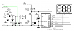
Implemented direct measurement of alternating voltage with subsequent calculation of its value and output to the indicator. The measured voltage is fed to the input divider, made on R3, R4, R5, and through the separating capacitor C4 is fed to the input of the ADC of the microcontroller.
Resistors R6 and R7 create a voltage of 2.5 volts (half power) at the input of the ADC. The relatively small capacitor C5 shunts the ADC input and helps to reduce the measurement error. The microcontroller organizes the operation of the indicator in dynamic mode by interrupts from the timer.
Construction and details
Option with power supply from the measured network 220 V. A simple 5 volt power supply is provided, this part is circled in a pale green line in the diagram. Such a module is used with direct power supply from the measured network. In this mode, the lower limit of the measured voltage will be about 150 volts.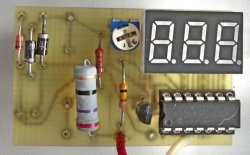

Option with additional power supply + 7…15 V. Measurement limits 0 - 250 Volts.


The voltmeter is assembled on a board made of one-sided foil fiberglass. The indicator is used with a common cathode.
Resistors R6 and R7 can have a value of 47 - 100 kohm. They must be selected with the same denominations or taken with a 1% tolerance. The linearity of the readings in the upper part of the scale depends on their equality of denominations.
The value of the resistors R8 - R12 is selected depending on the required brightness of the glow and the light output of the indicator. In this case, it may be necessary to increase the capacitance of the capacitor C1 to obtain a larger current value to power the indicator.
When using an indicator with low light output, it is advisable to use a more powerful 7805 instead of the U1 chip (78L05) in order to avoid overheating.
Setting
The voltmeter setting has no features. Before setting, it is advisable to wait 10 - 15 minutes after switching on. It is necessary to set the correct readings with resistors R5 (fine) and R3 (rough if required).Program
The program is written in C language (mikroC PRO for PIC) and provided with comments. The program used direct measurement of AC voltage microcontroller, which made it possible to simplify the circuit and improve the accuracy of measuring low voltages.Microprocessor used PIC16F676. Clock frequency internal oscillator 4 MHz.
Program operation: during a certain period of time, multiple direct voltage measurements are made without reference to the phase, and at the same time, the minimum and maximum voltage values are determined. The difference between their values will be equal to the range of the measured voltage, which is displayed on the indicator.
Possible applications of the voltmeter
Mains voltage measurement (measurement limits 150 - 250 Volts)Hello dear reader. Sometimes it becomes necessary to have a small, simple voltmeter “at hand”. Making such a voltmeter with your own hands is not difficult.
The suitability of a voltmeter for measuring voltages in certain circuits is judged by its input resistance, which is the sum of the resistance of the frame of the pointer device and the resistance of the additional resistor. Since the additional resistors have different ratings at different limits, then input impedance device will be different. More often, a voltmeter is evaluated by its relative input resistance, which characterizes the ratio of the input resistance of the device to 1 V of the measured voltage, for example, 5 kOhm / V. This is more convenient: the input resistance of the voltmeter is different at different measurement limits, and the relative input resistance is constant. The smaller the total deflection current of the arrow of the measuring device Ii used in the voltmeter, the greater will be its relative input resistance, the more accurate will be its measurements. In transistor designs, it is necessary to measure voltage from fractions of a volt to several tens of volts, and even more in lamp designs. Therefore, a single-limit voltmeter is inconvenient. For example, even voltages of 1-5V cannot be accurately measured with a voltmeter with a scale of 100V, since the deviation of the arrow will turn out to be hardly noticeable. Therefore, we need a voltmeter that has at least three to four measurement limits. The scheme of such a voltmeter direct current shown in Fig.1. The presence of four additional resistors R1, R2, R3 and R4 indicates that the voltmeter has four measurement limits. In this case, the first limit is 0-1V, the second is 0-10V, the third is 0-100V, and the fourth is 0-1000V.
The resistance of additional resistors can be calculated by the formula following from Ohm's law: Rd \u003d Up / Ii - Rp, here Up is the highest voltage of a given measurement limit, Ii is the total deflection current of the measuring head needle, and Rp is the resistance of the frame of the measuring head. So, for example, for a device for a current Ii \u003d 500 μA (0.0005A) and a frame with a resistance of 500 Ohms, the resistance of the additional resistor R1, for a limit of 0-1V should be 1.5 kOhm, for a limit of 0-10V - 19.5 kOhm, for a limit of 0 -100V - 199.5 kOhm, for the limit 0-1000 - 1999.5 kOhm. The relative input resistance of such a voltmeter will be 2 kOhm / V. Usually, additional resistors with ratings close to those calculated are mounted in a voltmeter. Finally, the “adjustment” of their resistances is carried out when calibrating the voltmeter by connecting other resistors to them in parallel or in series.
If we supplement the DC voltmeter with a rectifier that converts AC voltage to DC (more precisely, pulsating), we get a voltmeter alternating current. A possible circuit of such a device with a half-wave rectifier is shown in Fig. 2. The device works as follows. At those moments in time when there is a positive half-wave of alternating voltage on the left (according to the circuit) terminal of the device, the current flows through diode D1 and then through the microammeter to the right terminal. At this time, diode D2 is closed. During the positive half-wave on the right clamp, the diode D1 closes, and the positive half-waves of the alternating voltage are closed through the diode D2, bypassing the microammeter.
The additional resistor Rd is calculated in the same way as for constant voltages, but the result is divided by 2.5-3 if the device's rectifier is half-wave, or by 1.25-1.5 if the device's rectifier is full-wave - Fig. 3. More precisely, the resistance of this resistor is selected empirically during the calibration of the instrument scale. You can calculate Rd using other formulas. The resistance of the additional resistors of the voltmeters of the rectifier system, made according to the circuit in Fig. 2, is calculated by the formula:
Rd = 0.45? Up / Ii - (Rp + rd);
For the circuit in Fig. 3, the formula looks like:
Rd = 0.9? Up / Ii - (Rp + 2rd); where rd is the forward resistance of the diode.
The readings of the rectifier system instruments are proportional to the average rectified value of the measured voltages. Their scales are calibrated in the rms values of the sinusoidal voltage, therefore, the readings of the rectifier system devices are equal to the rms value of the voltage only when measuring sinusoidal voltages. D9D germanium diodes are used as rectifier diodes. Such voltmeters can also measure audio frequency voltages up to several tens of kilohertz. A scale for a homemade voltmeter can be drawn using the FrontDesigner_3.0_setup program.
If you use a voltmeter with a measuring head of a magnetoelectric system to measure direct voltage, then you paid attention that if the polarity of the voltmeter probes is connected to the source of the measured voltage, the arrow of the measuring head deviates in the opposite direction beyond zero and goes off scale. If you try to measure an alternating voltage with a frequency of about 50 Hz and higher with such a device, the arrow may twitch slightly at the initial moment of time, but after that it will point to zero. A non-zero value will indicate the presence of a constant voltage component.
The easiest way to get out of the situation is to convert the AC voltage to DC, that is, to straighten it. This is easy to do with a single diode, as shown in the article. If you want to measure the voltage more or less accurately, you can use for rectification.
Measurement schemes
The reason for this behavior of the magnetoelectric meter when measuring AC voltage is simple. In such devices there is a permanent magnet, and the direction of deviation of the arrow of the device depends on the direction of current flow in the coil of the rotating frame. At the moment of a positive half-cycle, the arrow of the device tries to deviate in one direction, while the negative one tries to deviate in the other. With a fairly frequent change of polarity, for example, as in a 50 Hz consumer network, the arrow simply does not have time to deviate in one direction, when suddenly it needs to deviate in the opposite direction. In this case, you can just notice the trembling of the arrow, or not notice anything.
The measuring heads of the electromagnetic system in their device do not have a permanent magnet, and their principle of operation is based on the phenomenon of drawing an object from a magnetizable material into the region of the center of the coil with current. The direction of action of a coil with current on a magnetized object does not depend on the direction of the current in the coil winding. Therefore, such devices easily measure both direct and alternating current or voltage.
If you need to measure the voltage in the AC network, and only a device with a measuring head of the magnetoelectric system (with a permanent magnet) is at hand, then you can simply get out of the situation by having at least one rectifier diode with a reverse voltage not lower than the amplitude value expected value to be measured. To do this, consider two schemes.
Circuit with one diode
Less accurate, but extremely simple option. All that is needed is to connect one of the probes of the device through a rectifier diode. In this case, it should be noted that the diode must be connected to the prior terminal with positive polarity by the cathode (to the negative - by the anode). Under the action of a positive half-cycle, the arrow will deflect the measured voltage value in the direction we need. During the negative half-cycle, the diode will turn off, breaking the circuit of the device with a voltage source that will no longer act on the arrow of the device in the opposite direction.
Single diode measurement feature
Determining the value of a quantity. When measuring according to the considered scheme, it should be taken into account that the device reacts only during one half-cycle, and will show a value two times less than the actual operating voltage value. That is, if, when measuring voltage with such a circuit, the device showed a value of 110 V, this reading must be multiplied by two, and you will get what you measured.
Diode selection. For right choice diode, we need to take into account the reverse voltage of the diode, which must be greater than the amplitude value of the measured value, otherwise the diode may break through, and the device will stop showing, or it may lie by several orders of magnitude. For example, we are going to measure the voltage in an outlet. When specifying the voltage class of the equipment, the effective value is indicated. To find out the amplitude value, you need to multiply the effective value by the root of two:. The consumer network voltage is 220 V. The voltage amplitude will be 220 × 1.41 \u003d 311 V. In our case, rectifier diodes with a reverse voltage of 400 V and higher are quite suitable. Below is not desirable, because. in the event of an overvoltage in the network, the voltage amplitude may exceed the reverse voltage of the diode, an irreversible breakdown will occur p-n junction and the diode will fail.
Also, do not choose high power diodes, the lower the power, the better. Power diodes have a large p-n area transition, which in the locked state can behave like capacitor plates. Thus, in the negative half-cycle, capacitive conduction may affect, and the readings of the device will be somewhat underestimated. The higher the frequency of the measured voltage, the greater the influence, especially when using high-resistance sensitive measuring heads.
Diagram with a diode bridge
 A more complex option, but allowing you to measure electrical quantities more accurately. This will require 4 diodes, or a ready-made diode bridge. The principle of operation of the circuit is similar to the first option, but here the measuring element feels both half-cycles of the voltage, which act on it in the same direction, and the device shows the effective value of the voltage. That is, the readings of the device will correspond to reality.
The choice of diodes or a diode bridge is similar to the first case.
Precautionary measures
When modifying your instrument in these ways, pay special attention to safety. Diodes or a diode bridge used in circuits, as well as contact points for cutting wires, instrument probes, voltmeter terminals must be securely insulated to prevent damage electric shock in case of accidental contact with current-carrying parts of the device during the measurement.