Alphabetical catalog
At present, when processing parts on various milling and boring machines, in the conditions of the main and repair production, a special tool is used. One of these devices is a boring cutter. It is used for making holes of large and small diameters to various depths. This boring is used in parts of the automotive industry, general mechanical engineering and instrumentation (gear housings, cylinder liners, bearing supports, and so on). 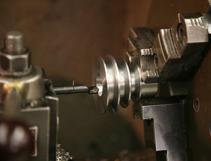
Cutter design
It consists of a carbide rod soldered into a steel shank, which has a flat working part. Currently, there are many new models of this device. Thanks to innovations in these tools, chip removal from the boring zone has been greatly improved. However, in any case, the boring cutter has a rod and a working part - a head. Therefore, the design of this tool is not complicated. 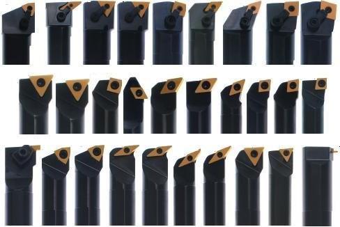 The rod has a rectangular or round section. It is usually made of quality carbon 45. The back of the shank is used for fastening in the mandrel, and the head is for mounting the cutting part, which, depending on size and modification, is in the form of a plate or insert and is made of P9, P18, P6M5. A little less common are these elements made of hard alloy (VK8, T5K10, T15K6) or mineral ceramics.
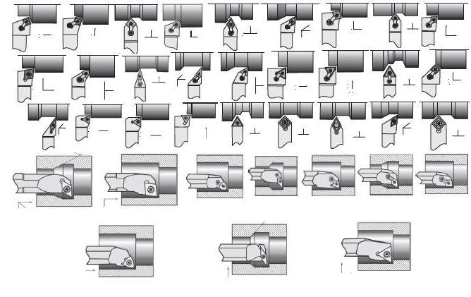
Cutter boring - sharpening
This process is not difficult if you have special equipment. This is done on The result is the required cutting geometry. The head of this tool is sharpened along with the cutting plate. The front, rear and plan angles are formed. The choice of tool geometry is carried out taking into account the properties of the material being processed and the processing modes.
Process features
The specificity of boring, especially of small diameters, is difficult chip removal. The work is carried out in a closed area, the chips accumulate, get knocked off, as a result, the cutting process becomes more difficult, heat dissipation worsens, and the machined surface may be damaged. To solve this problem, it removes heat and washes chips into special chip-breaking grooves on the front surface of the cutting part of the cutter. This is important in this case. Said groove is a well with a rounded bottom. As a result of the use of chip breaking elements, it is possible to avoid the formation of drain chips, which are woven into “beards” and block the operation of the tool, as a result of which the boring cutter may fail. 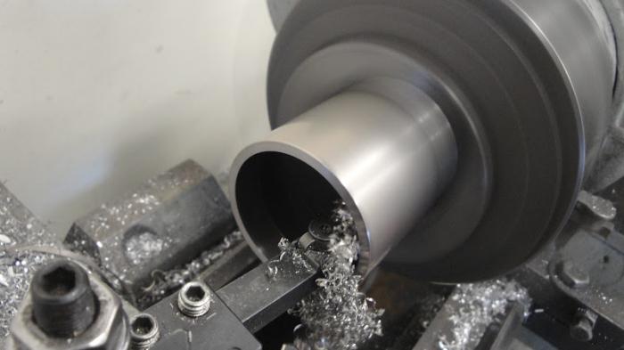
Fixture mounting
A boring cutter is installed in mandrels with sockets for installing the corresponding profile of the holder. They are different types. They also have a tapered shank according to GOST. The boring cutter is fixed mechanically. When processing deep holes or small diameters, adapter mandrels are used. They are selected so that they can be installed in the cone of the machine spindle. Short cantilever arbors allow you to set two cutters at the same time and work as a combination tool, which increases productivity when finishing large holes. It is convenient in this case. Hole processing is also carried out on universal machines where boring is applied. From the usual specified tool, it differs in the size of the holder and the method of fastening. Mandrel is not used here. The shank of the cutter has a massive section (25x25, 32x25, 40x40 mm) and is fixed in the tool holder with screws.
Properties of tool materials Cutting tools operate under conditions of significant force loads, high temperatures , friction and wear. Therefore, tool materials must have certain operational and physical-mechanical properties. The material of the cutting part of the tool has a high hardness and high values of allowable bending, tension, compression and torsion stresses. The hardness of the cutting part of the tool must significantly exceed the hardness of the workpiece material. Carbon tool steels contain 1.0 ... 1.3% C. For the manufacture of tools, high-quality steels U10A, U11A, U13A are used. After heat treatment, the steels have a red hardness of 200–240 °C. At this temperature, the hardness of the steel decreases sharply, and the tools cannot do the work of cutting. Permissible cutting speeds do not exceed 0.2...0.3 m/s. Taps, dies, hacksaw blades, drills and countersinks of small diameters are made from these steels. Alloy tool steels are carbon tool steels alloyed with chromium, tungsten, vanadium, silicon and other elements. After heat treatment, alloyed steels have a red hardness of 220...260 °C. Compared to carbon alloy steels, they have increased toughness in the hardened state and higher hardenability, less tendency to deformation and cracking during hardening. Permissible cutting speed 0.25…0.5 m/s. For the manufacture of broaches, drills, taps, dies, reamers, steels 9X VG, KhVG, KhG, 6XC, 9XC are used. High-speed steels contain 5.5 ... .19% W, 0.7 ... 1.2% C; 2 ... 10% Co and V. For the manufacture of tools, steels R9, R12, R18, R6M3, R6M5, R9F5, R14F2, R9K5, R9K10, R10K5F2 are used. In all high-speed steels, the mass fraction of chromium is 4%, therefore, the letter X is not indicated in the brand designation. The cutting tool made of high-speed steel, after heat treatment, has a red hardness of 600 ... 640 ° C and has increased wear resistance, therefore it can work at cutting speeds up to 2 m / s. To save high-speed steels, the cutting tool is made prefabricated or welded. The cutting part of the tool is made of high speed steel, which is welded or mechanically connected to the connecting part of structural steels 45, 50, 40X. Hard alloys include tool materials consisting of highly hard and refractory carbides of tungsten, titanium, tantalum, connected by a metal bond. These materials are produced by powder metallurgy. Carbide powders are mixed with cobalt powder, pressed and sintered at 1400. ...1550 oC. During sintering, cobalt dissolves part of the carbides and melts. As a result, a dense material is obtained, the structure of which consists of 80 ... 85% of carbide particles connected by a binder. Hard alloys are used in the form of plates of a certain shape and size, which are divided into three groups: - tungsten - VK2, VK3, VK3M, VK8, etc.; - titanium-tungsten - T30K4, T15K6, T14K8, T5K10, T5K12V; - titanium-tantalum-tungsten - TT7K12, T10K8B. Hard alloy plates have high wear resistance and red hardness (800....1250 °C), which allows cutting at cutting speeds up to 15 m/s. The plates are soldered to holders or tool bodies with copper, brass solders or fixed mechanically. The most widely used among superhard materials (STMs) are materials based on cubic boron sodium (Elbor, Hexanite - R, Cyborite, etc.). They are produced in the form of plates of various geometric shapes, which are equipped with cutting tools. STM is used for fine, fine turning and milling of hardened steels and cast irons. Tool ceramic materials can be divided into groups that differ chemical composition, method of production and areas of rational use. Oxide "white" ceramics, consisting of Al2O3 with alloying additives MgO, ZrO2, etc., is used for finishing and semi-finishing of non-hardened steels and gray cast irons with cutting speeds up to 15 m/s. Oxide-carbide "black" ceramics, consisting of Al2O3, TiC, ZrO2 and other carbides of refractory metals, is used for processing malleable, high-strength and chilled modified cast irons and hardened steels. Silicon nitride-based ceramics are used for semi-finishing of cast irons. High strength properties are necessary in order for the tool to be resistant to the corresponding deformations during the cutting process, and sufficient viscosity of the material makes it possible to absorb the shock dynamic load. Tool materials must have high red hardness (heat resistance), i.e. the ability to retain hardness when heated. Red hardness is evaluated by the temperature at which a sharp decrease in the hardness of the material occurs. The most important characteristic material of the cutting part of the tool serves wear resistance. The higher the wear resistance, the slower the tool wears and the higher its dimensional stability. This means that workpieces machined sequentially with the same tool will have a minimum dispersion in the dimensions of the machined surfaces. Materials for the manufacture of tools should, if possible, have the smallest percentage of scarce elements. The following materials meet all of the above requirements to one degree or another: tool steels, hard alloys, synthetic superhard and ceramic materials, abrasive and diamond materials.
Holes are bored on lathes with boring cutters (Fig. 118). Depending on the type of bored hole, there are: boring cutters for through holes (Fig. 118, a) and boring cutters for blind holes (Fig. 118, b). These incisors differ from each other in the main angle in terms of f. When boring through holes (Fig. 118, a), the main angle in terms of f \u003d 60 °. If a blind hole is bored with a ledge of 90 °, then the main angle in terms of f \u003d 90 ° (Fig. 118, b) and the cutter works as a hard-through or f = 95 ° (Fig. 118, c) - the cutter works with longitudinal feed as a thrust-through, and then with a transverse feed as a scoring.
Boring tool sharpening angles
On fig. 118 shows the grinding angles of boring cutters, which are chosen basically the same as for cutters for external turning, with the exception of the back angle a, which usually has an increased value for boring cutters. The value of the back angle depends on the diameter of the bored hole: the smaller the diameter of the hole, the larger the back angle of the cutter should be.
Rice. 118. Boring cutters equipped with hard alloy plates: a - through-hole for processing through holes, b and c - hard-through for processing blind holes
The complexity of the operation
Boring is a more complicated operation than external turning of surfaces, since:
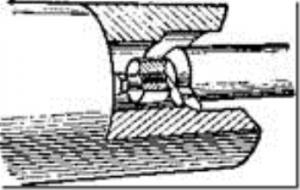
- when boring, the size of the cross-section of the cutter should be significantly smaller than the diameter of the hole, and the cutter overhang from the cutter head is somewhat larger than the length of the bored hole (Fig. 119), therefore, when boring a hole of considerable length, the cutter may bend, and at high cutting speeds - strong vibrations. Consequently, such cutters do not make it possible to cut chips of large cross section;
- when boring, it is less convenient to observe the work of the cutter, since cutting takes place inside the hole.

Rice. 119. Boring a hole with a cutter
For boring holes with a diameter of up to 70 mm, the innovator turner V.K. Seminsky proposed a special boring cutter equipped with a hard alloy plate (Fig. 120). The cutter rod has a square section along its entire length, the working part of the cutter is turned by twisting during manufacture at an angle of 45° relative to the supporting part. Such a cutter is distinguished by increased rigidity compared to a conventional boring cutter and allows an increase in the chip cross section by 4-5 times. When working with such a cutter with an increased cutting speed, vibrations are not observed even with a significant overhang of the holder.
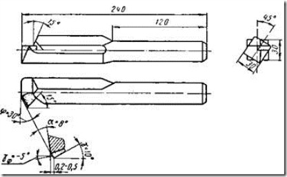
Rice. 120. Boring cutter equipped with a hard alloy plate, designed by V. K. Seminsky
To increase the vibration resistance of the cutter, the innovator turner V. Lakur proposed a new design of a boring cutter with a hard alloy plate (Fig. 121). A feature of these cutters is that their main cutting edge is located at the level of the neutral axis of the rod. This arrangement of the cutting

Rice. 121. Boring cutter designed by V. Lakura
edge provides cutters with a significant increase in vibration resistance and, as a result, makes it possible to work at high cutting speeds and achieve improved surface finish.
Rice. 122. Mandrel with a cutter for boring a through hole
Installing the cutter
Holes of great length are bored with cutters fixed in special massive mandrels, the dimensions of which depend on the diameter of the hole and its length. Replacing a solid boring bar with a small bar inserted into a boring bar results in significant savings in expensive tool material. The method of fastening the cutter in the mandrel depends on its purpose. On fig. 122 shows a mandrel for boring a through hole; here the cutter is located at a considerable distance from the end of the mandrel. For boring blind holes, the cutter is mounted in such a way that it protrudes somewhat beyond the front end of the mandrel.
Before boring a hole, it is necessary to set the cutter to the required diameter along the dial of the cross feed screw, and then bore the hole by manual feed to a length of 2-3 mm. Having measured the diameter with a caliper or other measuring device and making sure that the size is correct, bore the hole to the rest of the length. It is especially important to correctly set the cutter to the required diameter when fine boring.
The position of the cutting edge of the cutter depends on the type of boring. When rough boring, it is recommended to set the cutting edge at the height of the centers or slightly lower. When fine boring, the cutting edge should be located above the center line by about 1/100 of the hole diameter, given that due to the force arising from the resistance of the sheared chip, the cutter can be pressed down.
- 6196 views
Boring cutters are designed for boring through or blind holes already existing in products. The deeper the hole, the longer the round part of the cutter shaft should be. However, a cutter that is too thin and protruding far during operation springs and moves somewhat away from the surface being machined, reducing both the machining accuracy and surface finish.
Boring cutters are used to process holes. They work in less favorable conditions than external turning cutters. Boring cutters should have smaller transverse dimensions than the hole being machined. They get long. The overhang of the cutter must be greater than the length of the bored hole. Due to the low rigidity, boring cutters are prone to vibrations, which makes it impossible to remove large chips.
Khrapunovsky plant
Khrapunovsky tool factory (Khrapunovsky tool) was founded in 1960. Produces metal-cutting tools, including cutters. The production process is organized in such a way that it allows to fulfill non-standard orders.
Kanash plant
The Kanash cutter plant was founded in 1937. Since the first half of the 20th century, it has been producing high quality cutting tools.
Kirzhach plant
Kirzhach Tool Plant (KI3) was founded in 1934. Produces a wide range of metal cutting tools, includingsoldered turning cutters.
Turning cutters with brazed inserts made of hard alloys T15K6, T5K10, VK8, from T30K4 on order.
Prices are valid for purchases from 30 thousand rubles. Specify the final price with the manager.
Production of cutters with a plate made of P18 high-speed steel on order.
| Name | price, rub. |
|---|---|
| Boring cutters for through holes type 1 version 1 GOST 18882-73 | |
| Boring cutter for through holes type 1 version 1 12x12x130 | 70,8 |
| Boring cutter for through holes type 1 version 1 16x16x120 | 86,14 |
| Boring cutter for through holes type 1 version 1 16x16x140 | 86,14 |
| Boring cutter for through holes type 1 version 1 16x16x170 | 90,9 |
| Boring cutter for through holes type 1 version 1 20x20x140 | 119,8 |
| Boring cutter for through holes type 1 version 1 20x20x170 l=50 | 108,6 |
| Boring cutter for through holes type 1 version 1 20x20x170 l=70 | 113,3 |
| Boring cutter for through holes type 1 version 1 20x20x200 | 122,72 |
| Boring cutter for through holes type 1 version 1 25x25x200 | 162,8 |
| Boring cutter for through holes type 1 version 1 25x25x240 | 182,9 |
| Boring cutters for through holes type 1 version 2 GOST 18882-73 | |
| Boring cutter for through holes type 1 version 2 16x10x170 | 181,72 |
| Boring cutter for through holes type 1 version 2 16x12x170 | 141,6 |
| Boring cutter for through holes type 1 version 2 20x16x170 | 188,8 |
| Boring cutter for through holes type 1 version 2 25x16x200 | 236 |
| Boring cutter for through holes type 1 version 2 25x20x240 | 283,2 |
| Boring cutter for through holes type 1 version 2 32x25x280 | 696,2 |
| Boring cutter for through holes type 1 version 2 40x32x300 | 849,6 |
| Boring cutter for blind holes type 1 version 1 GOST 18883-73 | |
| Boring cutter for blind holes type 1 version 1 12x12x130 | 70,8 |
| Boring cutter for blind holes type 1 version 1 16x16x120 | 86,15 |
| Boring cutter for blind holes type 1 version 1 16x16x140 | 86,15 |
| Boring cutter for blind holes type 1 version 1 16x16x170 | 90,9 |
| Boring cutter for blind holes type 1 version 1 20x20x140 | 119,1 |
| Boring cutter for blind holes type 1 version 1 20x20x170 | 119,1 |
| Boring cutter for blind holes type 1 version 1 20x20x200 | 121,6 |
| Boring cutter for blind holes type 1 version 1 25x25x200 | 162 |
| Boring cutter for blind holes type 1 version 1 25x25x240 | 182 |
| Boring cutter for blind holes type 1 version 2 GOST 18883-73 | |
| Boring cutter for blind holes type 1 version 2 16x10x170 | 141,6 |
| Boring cutter for blind holes type 1 version 2 20x16x200 | 240 |
| Boring cutter for blind holes type 1 version 2 25x16x200 | 324,5 |
| Boring cutter for blind holes type 1 version 2 25x20x240 | 356,95 |
| Boring cutter for blind holes type 1 version 2 32x25x280 | 696,2 |
| Boring cutter for blind holes type 1 version 2 40x32x300 | 849,6 |
| One-piece boring cutter st.hv. for deaf people VK6M 5x10x45 | 60 |
| One-piece boring cutter st.hv. for deaf people 3.8x6x20x50 VK6M GOST 18063-72 version 2 | 50 |
| Boring cutter for through and blind holes D20x170 | 129,8 |
| Boring cutter for through and blind holes D25x200 | 165,2 |
| Fine turning cutter wide 25x16x140 | 236 |
| Fine turning cutter wide 32x20x170 | 295 |
Metal work is always done with special devices because without them it would be simply impossible. The cutters have firmly entered the metalworking industry. It doesn't matter what is used boring tool, threaded cutter or something else. It is important that the use of this thing is associated with a certain, specific work.
You may think that cutters (carbide, bent, thrust, etc.) are all used in the same way, the difference is only in shape. But it's not. Each type of incisor has its own functions that it performs better than others, as well as its own disadvantages, based on which you will understand how a particular type of incisor should not be used.
When choosing the necessary cutter, you need to take responsibility for the preparation before choosing. Having studied the proposed options in advance, you will not be distracted, it will not be possible to distract you with a beautiful name - you will simply be immediately focused on what you need in practice, and not in theory.
Special types of boring cutters
A cutter is a cutting tool (it was named according to the type of action), intended for work with metal objects (parts, blanks). It is mainly used on turning, slotting, planing machines for the same type of work. The principle of its operation is the gradual, layer by layer, removal of metal in the right places. Obviously, due to the specifics of the work performed, the cutter always has a cutting edge. The most popular types of cutters are boring cutter, through cutter, cut-off cutter.
But the variety of incisors is not limited to these types, they are simply used less often due to the specificity of the work performed.
The boring cutter has its own specifics of work. Its use involves boring already created through holes, blind holes. These holes are created during drilling, stamping, casting of the workpiece, but they need to be finished with a cutter.
The boring cutter is used for boring holes with a diameter of more than 40 mm in body parts. The cutters are fixed in the sockets of boring bars in a perpendicular (ξ = 90o) or inclined (ξ = 45, 60o) position with respect to the axis of the mandrel.
The fastening of tool holders in the sockets of mandrels and boring bars is carried out unregulated or adjustable with an installation accuracy of up to 0.005 mm.
When the cutter is inclined relative to the axis of the hole at some angle ξ, the angles in the plan at the cutter change: φН = φ + ξ; φ1Н = φ1 – ξ. This must be taken into account when designing the cutter.
Cutting mode parameters: depth of cut, 2 0 t mm D DP, where Dp is the diameter of the preliminary hole; D0 is the diameter of the final hole; allowable cutting speed m/min; T t S C K V m x v y v V V T - spindle speed; 1000 1 0 min D V n T - feed longitudinal (Sp) or transverse (Sp) (mm / rev); minute feed Smin=S∙n (mm/min).
The boring cutter has its own classification.
They are often divided depending on the type of construction:
- Straight lines (the line of the head axis is parallel to the holder axis).
- Bent (the head of the cutter deviates to the side).
- Curved (holder axis has a bend).
- Drawn (tool cooking already).
- Others (creations of innovators that are not widely used).
Each type of boring cutter has its own specifics of use, coping better in some jobs, worse in others. Boring cutters are used in cases where there are no drills or countersinks of the required diameter, the accuracy and straightness of the entry of the hole must be ensured, other types of processing are not accurate enough and “clean”, with a small hole length, with a hole width that goes beyond the largest diameters of another equipment. We can safely say that the boring cutter, although not universal, is quite a demanded item that will find application in any metalworking enterprise.
The boring bar and other options are often used, although there are alternatives for them in most cases. It's just that cutters are much easier to use, since there is practically no human factor when processing a part with a cutter.
You need to buy a boring cutter carefully, consciously. Read the information, draw conclusions about what types of work they will have to perform, what characteristics you need from it. Pay attention to manufacturers - Internet searches may well tell you who you can trust, and whose products are questionable by consumers. Conscious purchases always last much longer than those that were made on a "come, buy" basis. The specialists of our company will advise on all issues of interest.