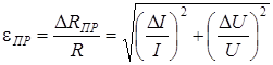
Determine the relative error in measuring voltage 100V with a voltmeter. Resistance measurement errors
1.1. A voltmeter of accuracy class 1.0 with a measurement limit of 300 V, having a maximum number of divisions of 150, was verified at 30, 60, 100, 120 and 150 divisions, while the absolute error at these points was 1.8; 0.7; 2.5; 1.2 and 0.8 V. Determine whether the device corresponds to the specified accuracy class, and the relative errors at each mark.
Solution. A voltmeter of accuracy class 1.0 with a measurement limit of 300 V has the largest absolute error of 3 V. Since the value of the absolute error at all verified marks is less than 3 V, the device corresponds to an accuracy class of 1.0.
Relative errors:
1.2. It is necessary to measure the consumer current within 20 - 25 A. There is a microammeter with a measurement limit of 200 μA, an internal resistance of 300 Ohm and a maximum number of divisions of 100. Determine the resistance of the shunt to expand the measurement limit to 30 A and determine the relative measurement error at around 85 divisions, if instrument accuracy class 1.0.
Solution. You must first determine the shunt coefficient: ![]() . Then
. Then ![]() . We determine the ammeter reading corresponding to 85 divisions, for which we multiply the division value of 0.3 A / division by the number of divisions of 85, then the device will show I \u003d 25.5 A. The relative error at this point DI max \u003d 0.3A.
. We determine the ammeter reading corresponding to 85 divisions, for which we multiply the division value of 0.3 A / division by the number of divisions of 85, then the device will show I \u003d 25.5 A. The relative error at this point DI max \u003d 0.3A.
1.3. To the network alternating current through the current transformer 100 / 2.5 A and the voltage transformer 600 / 150 V, an ammeter, voltmeter and wattmeter are included, which showed 100, 120 and 88 divisions, respectively. The measurement limits of the devices are as follows: ammeter - 3 A, voltmeter - 150 V, wattmeter - for current 2.5 A, for voltage 150 V. All devices of accuracy class 0.5 have a maximum number of divisions of 150. Determine the total power consumed by the network, its total resistance and power factor; the largest absolute and relative error in the measurement of impedance, taking into account the accuracy class of the instruments.
Solution. We determine the division price of each device as the ratio of the measurement limit to the maximum number of divisions. For an ammeter, the division value is 0.02 A / div, for a voltmeter - 1 V / div, for a wattmeter - 2.5 W / div.
Then the instrument readings: I = 0.02 × 100 = 2A; U = 1 × 120 = 120 V; P = 2.5 × 88 = 220 W.
Transformation ratios K I \u003d I 1nom / I 2nom \u003d 100 / 2.5 \u003d 40; To U \u003d U 1nom / U 2nom \u003d 600 / 150 \u003d 4.
Then the current, voltage and active power of the network:
The total power consumed by the network is determined through current and voltage:
Power factor
![]() .
.
Mains impedance
![]() Ohm.
Ohm.
Highest value total resistance
![]() Ohm
Ohm
where is the absolute error
Relative measurement error
![]() %.
%.
1.4. Using the method of an ammeter and a voltmeter, the resistance is measured according to the scheme of fig. 8.2, A. The readings of the ammeter and voltmeter were as follows: U = 4.8V, I = 0.15A. The devices have an accuracy class of 1.0 and measurement limits I pr \u003d 250 mA, U pr \u003d 7.5 V. Determine the measured resistance, the largest absolute and relative measurement errors.
Solution. Measured resistance ![]() Ohm. The largest absolute error of the voltmeter and ammeter, respectively, with the specified limits and accuracy class 1.0 V; A. The highest value of the measured resistance, taking into account the accuracy class of the applied devices Ohm. Then the relative measurement error is %.
Ohm. The largest absolute error of the voltmeter and ammeter, respectively, with the specified limits and accuracy class 1.0 V; A. The highest value of the measured resistance, taking into account the accuracy class of the applied devices Ohm. Then the relative measurement error is %.
1.5. Passport data of the electric energy meter: 220 V, 10 A, 1 kWh - 640 disk revolutions. Determine the relative error of the meter and the correction factor if it was tested at nominal values of current and voltage and for 10 minutes. made 236 revolutions.
Solution. We determine the nominal and actual constants of the counter:
![]() W×s/rev.
W×s/rev.
Counter correction factor ![]() .
.
Relative counter error %.
1.6. The secondary winding of the current transformer TKL-3 is designed to turn on an ammeter with a measurement limit of 5 A. The accuracy class of the instruments is 0.5. Determine the rated current in the primary circuit and in the ammeter, the measurement errors of the instruments, if the transformation ratio is K I \u003d 60, and the primary circuit current I 1 \u003d 225 A.
1.7. A 100 V voltmeter with a scale of 100 divisions is connected to the secondary winding of the NOSK-6-66 voltage transformer (U 1 = 6000 V). Determine the mains voltage if the voltmeter needle stops at the 95th division. Determine the errors in the measurement by instruments of the first accuracy class.
Solution. According to the voltage transformer, we determine the transformation ratio: ![]() . Voltage in the primary circuit when the instrument reads. Relative error of voltage measurement of the voltmeter
. Voltage in the primary circuit when the instrument reads. Relative error of voltage measurement of the voltmeter ![]() . General relative error .
. General relative error .
1.8. A 5 A ammeter, a 100 V voltmeter and a 5 A and 100 V wattmeter (with a scale of 500 divisions) are connected through a measuring current transformer TSHL-20 10000/5 and a voltage transformer NTMI-10000/100 for measuring current, voltage and power . Determine the current, voltage, active power and power factor of the primary circuit, if secondary circuit measuring current transformers I 2 \u003d 3 A, voltage U 2 \u003d 99.7 V, and the readings of the wattmeter are 245 divisions.
Solution. Rated transformer ratio of the current transformer ![]() . Rated voltage transformer ratio
. Rated voltage transformer ratio ![]() . Current in the primary winding of the transformer. Circuit voltage. Active power of the circuit. Circuit power factor
. Current in the primary winding of the transformer. Circuit voltage. Active power of the circuit. Circuit power factor ![]() .
.
BASICS OF THE THEORY
Ohm's law for a homogeneous section of a chain.
If at the ends of a homogeneous section of the circuit there is a potential difference Dj=j 2 -j 1 , then in this chain arises electricity. Current strength I, flowing through this section, is proportional to the potential difference DJ at the ends of the section and is inversely proportional to the resistance R this section of the circuit (or this conductor)
Value U = I×R is called the voltage drop across the conductor and is numerically equal to the amount of heat released in the conductor when a unit electric charge passes through it.
For a homogeneous section (i.e., not containing emf), the potential difference at the ends of the section is numerically equal to the voltage drop in this section, i.e. . DJ = U.
If normal analog voltmeter(the deviation of the arrow of which is due to the current passing in the frame or coil) attach to the points 1 And 2 section of the circuit, it will show the potential difference Dj between these points. The potential difference in this case will be equal to the voltage drop U on a voltmeter, i.e.
Where R v- resistance of the voltmeter,
Iv is the current flowing through the voltmeter.
conductor resistance.
If the circuit section is a conductor of length l constant cross section S, homogeneous chemical composition, then the resistance R this conductor is determined by the formula:
where r is the resistivity of the material.
Resistivity is numerically equal to the resistance of a homogeneous conductor of unit length and unit section. It depends on the chemical composition of the conductor material, its temperature, and is measured in the SI system in Ohm × m. In practice, an off-system unit is often used - Ohm × mm 2 / m
At room temperature conductors made of chemically pure metals have the lowest resistivity. The specific resistance of alloys is large, which allows them to be used for the manufacture of resistors with high resistance (rheostats, heating elements, shunts and additional resistances). In table. 1 gives the resistivity values of some materials.
Table 1.
Methods for measuring resistance.
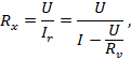
One of the methods for measuring the resistance of a conductor is the "ammeter-voltmeter" method, which consists in the practical use of Ohm's law for a homogeneous section of the circuit. From formulas (1) and (2) it follows
those. measuring the potential difference U at the ends of the conductor and the magnitude of the current I flowing through him, you can determine the resistance R conductor.
Another method for measuring resistance is the bridge method, which is covered in another lab. Bridge circuits do not need to measure currents and voltages, so they give more accurate results.
Resistance measurement errors.
During measurements, errors occur, which have a different nature. The error of the method (or theoretical error) is associated with the imperfection of the method, with the simplifications adopted in the equations for measurements. The error of the method manifests itself, first of all, as a systematic one, to compensate for which it is possible to introduce corrections. When measuring resistance using the "ammeter-voltmeter" method, an error occurs, determined by the method of connecting the ammeter and voltmeter to the circuit section under study.
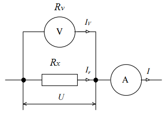
For resistance measurement R voltmeter and ammeter can be included in the circuit according to one of the circuits shown in Fig. 1
In circuit 1a (technical method with accurate current measurement), the voltmeter measures the potential difference U=j-j on series-connected conductors with resistance R and ammeter PA resistance R A. Therefore, the potential difference measured by a voltmeter between the points 1 And 2 , will be equal to sum voltage drop across the resistance R conductor and resistance R A ammeter:
![]() (5)
(5)
 |
a b
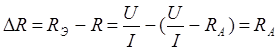
The calculation according to formula (4) will contain a systematic error due to the peculiarities of the method (simplifications adopted in such a calculation).
where through U the potential difference in the area is indicated 1-2 .
Therefore, the difference D R between resistance measurements R E according to formula (4) and true R and is the methodological error that occurs with this method of turning on measuring instruments.
 (7)
(7)
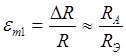 (8)
(8)
Those. the resistance measurement accuracy will be the greater, the lower the resistance R A ammeter versus resistance R conductor. (An ammeter with an infinitesimal self-resistance would be ideal.)
In the scheme 1b(technical method with accurate voltage measurement) is measured by an ammeter total current I, flowing through resistance R and voltmeter PV having its own resistance R v. The potential difference in this case is the same for both the conductor and the voltmeter.
Then according to Ohm's law (1):
Where I R And I V- currents flowing through the conductor and voltmeter, respectively PV , U- potential difference measured by a voltmeter.
Since the measured current is I = I R + I V then, taking into account (9), we obtain

If we do not take into account the current IV, flowing through the resistance RV of the voltmeter, then the resistance value R E of the conductor can also be found using the simplified formula (4).
The value of the true resistance R of the conductor will be equal to
 (10)
(10)
 (10’)
(10’)
Therefore, in this method of measurement, the error of the method also arises.
![]()
The relative error of this method is:
![]() (11)
(11)
those. the resistance measurement accuracy will be the greater, the greater the resistance of the voltmeter compared to the resistance R conductor Ideal would be a voltmeter with an infinitely large self-resistance. High-resistance are electronic analog and digital voltmeters introducing a small error.
Method errors arise when formula (4) is used. They can be corrected if the resistances of the ammeter are known. R A or voltmeter R V. Formulas (6) and (10) give an already corrected measurement result, free from this type of error.
Another source of error is instrumental errors due to instrument design. Instrumental errors contain both systematic and random components. For each individual resistance measurement R we make current measurements I and potential difference U with an error determined by the accuracy class of the measuring device
![]()
where g A- accuracy class of an ammeter with a limiting current I m,
g V- voltmeter accuracy class with limit Um.
The error in determining the resistance due to instrument errors is determined according to the rules for transferring errors of indirect measurements
 (12)
(12)
 (12’)
(12’)
![]() (13)
(13)
 (13’)
(13’)
From formulas (13) - (13"), it can be seen that the instrumental error can be reduced by using an ammeter and a voltmeter of a high accuracy class, as well as choosing currents and voltages of such a magnitude that the arrows of the instruments when taking readings are in the second half of the scale (possibly closer to measurement limit).
Random errors arise from a combination of factors that are not reproducible from measurement to measurement: instability of the current source, operator error, random component of instrumental error, etc. To determine the random error, a series of multiple measurements is carried out R i at different currents and voltages. Statistical error D R ST is determined in accordance with the rules for processing multiple measurements.
The total error is determined by the composition of the instrument D R OL and statistical D R ST errors
![]() (14)
(14)
INSTALLATION DESCRIPTION
The FRM-01 device is shown in Fig.2. A column (2) with a millimeter scale (3) is attached to the base (1). Two fixed brackets (4) and one movable bracket (5) are fixed on the column, which can move along the column and be fixed in any position. A nichrome wire (6) is stretched between the upper and lower brackets.
 |
Rice. 2
A good galvanic connection to the wire is ensured through the contact clamp on the movable bracket. On the movable bracket there is a line that makes it easier to determine the length of the measured nichrome wire on a scale. The lower, upper and central moving contacts of the nichrome wire are connected with low resistance wires to the measuring part of the device (7), which is located in the central building.
An ammeter is located on the front panel of the case. PA, voltmeter PV, key W1 for connecting the unit to a 220 V network, switches W2 And W3, rheostat handle R1 current adjustment. Depressed switch key W3 allows the use of nichrome wire in bridge circuits for measuring resistance. Key pressed W3 allows you to measure the active resistance of the wire using an ammeter and voltmeter.
If the key W2 pressed, then the measurement takes place according to the scheme of Fig. 1a - a technical method with accurate measurement of current, if pressed - according to the scheme of Fig. 1b - a technical method with accurate measurement of voltage.
COMPLETING OF THE WORK
1. Prepare a table of measurement results.
table 2
3. Turn on the unit and take five resistance measurements at different currents using the accurate current measurement method.
4. Prepare a table similar to Table. 2. Make a similar series of measurements using the accurate voltage measurement method.
5. Turn off the unit.
PROCESSING THE RESULTS
1. Calculate uncorrected R e i and corrected value R i conductor resistance according to the formulas (4), (6)
And (10),
as well as their average values
2. Determine the errors of the method e m1 and e m2 formulas (8) And (11) for each measurement method.
3. Determine instrument errors DR OL and e R for two experiments according to the formulas (12)-(13") (for minimum and maximum current) using the data of a more accurate method.
4. Determine the random error DR ST and e ST(for a more accurate method).
5. Determine the total absolute and relative errors of resistance measurement DR and e R formulas (14) and (14").
6. Determine the resistivity r of the nichrome wire using the formula (3).
7. Derive a formula for determining the error according to the rules for estimating the errors of indirect measurements (through the errors DR, Dd, And Dl). Define absolute and relative Dr errors for the most accurate measurement result
CONCLUSIONS
1. Write down the measurement result R And r in standard form.
2. Which resistance measurement method is more accurate? Confirm this by comparing the errors of both methods of switching on an ammeter and a voltmeter.
3. What type of error (method, instrumental or statistical) has the greatest influence on the result of determining the resistance error in your experiments?
4. Should the resistance of the ammeter and voltmeter be taken into account in these experiments?
CONTROL QUESTIONS
1. Give a definition of the potential difference and voltage drop in the circuit section. In which case are they equal?
2. What is the physical meaning of the resistance of a conductor? What does it depend on?
3. What is the resistance measurement method with accurate current measurement? What is wrong with this method? What is it equal to, and how can it be reduced?
4. What is the resistance measurement method with accurate voltage measurement? What is wrong with this method? What is it equal to, and how can it be reduced?
5. How are instrumental and random measurement errors determined in this work?
LITERATURE: ; ; .
Task №1………………………………………………………………………3
Task №2…………………………………………………………………………6
Task №3…………………………………………………………………..9
LIST OF USED SOURCES………………………13
Task number 1. Verification of technical instruments and the basics of metrology
Technical ammeter of magnetoelectric system with rated current I nom =5A, number of nominal divisions A nom = 100 has digitized divisions from zero to the nominal value, marked on every fifth part of the scale (the needles of de-energized ammeters occupy the zero position). Absolute error: +0.03, +0.06, -0.05, +0.04, -0.02.
Verification of the technical ammeter was carried out with an exemplary ammeter of the same system.
1. Specify the conditions for verification of technical devices.
2. Determine measurement corrections.
3. Build a schedule of amendments.
4. Determine the relative error.
5. Determine the reduced error.
6. Indicate to which nearest standard accuracy class this device belongs.
If the device does not correspond to the established accuracy class, indicate this specifically.
1. Verification is carried out in a room with normal conditions for working devices. The ammeter is verified by comparing the readings of a reference ammeter. In an ammeter with an accuracy class of 1.0; 1.5; 2.5; 5.0 is checked by comparing their readings with the readings of samples of devices of class 0.2 and 0.5.
2. Knowing the absolute error for each digitized division of the scale (1; 2; 3; 4; 5). We determine the measurement corrections, given that the correction is the absolute error, taken with the opposite sign:
- θ 1 = -0,03
- θ 2 = -0,06
- θ 3 = +0,05
- θ 4 = -0,04
- θ 5 = +0,02
3. To build a graph of corrections, we draw coordinate axes: horizontal, on which the digitized values of the scale divisions will be plotted, and vertical - for postponing corrections - up positive, down negative.
4. Relative error is calculated by the formula:
![]()
where X and is the measured value of the quantity;
X d - the actual value of the quantity.
5. Based on the definition given above, the reduced error is determined by the formula:
![]() ,
,
where X n and X k are the initial and final points of the instrument scale;
X and − the measured value of the quantity;
X d - the actual value of the quantity;
D - measurement range.
The remaining calculation results were performed similarly and are listed in Table 1.
Table 1
6. The accuracy class of a measuring instrument is a generalized characteristic determined by the limits of permissible basic and additional errors, as well as other properties that affect accuracy, the values of which are set in the standards for certain types of measuring instruments.
The largest reduced error of the device in percent at all marks of the working part is modulo 1.2%, so we determine the value of the accuracy class (the closest normalized value exceeding the value of the reduced error) from the standard range. The accuracy class of the verified ammeter is 1.5.
Task number 2. Methods and errors of electrical measurements
To measure the resistance indirectly, two instruments were used: an ammeter and a voltmeter of the magnetoelectric system.
The resistance measurement was carried out at a temperature t°C with devices of group 2, 5 or 6. Data of devices, their readings, as well as a group of devices and ambient temperature at which the resistance was measured, U nom \u003d 30V, I full \u003d 7.5 mA, \u003d 1.0%, U =18V, I nom =15A, U pad =100mV, =1.5%, I=8A, instrument group 6, t=40 ºС
Define:
1) resistance value r’ x according to instrument readings and draw a diagram;
2) resistance value r x taking into account the scheme for switching on devices;
3) the most possible (relative δ and absolute Δ) errors in the result of measuring this resistance;
4) in what limits are the actual values of the measured resistance.
1. The amount of resistance R' x is determined by the formula:
where U - voltmeter readings, V;
I - ammeter readings, A.
![]()
To choose the right schema, you must first define the relationships and
where U pad - voltage drop at the terminals of the device, mV;
I nom - measurement limit, A.
![]()
where U nom - measurement limit, V;
I full - the current of the total deviation of the arrow of the device, mA.
![]()
![]()
![]()
Choose a scheme:
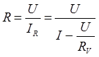
2. Find the resistance value Rx taking into account the scheme of switching on devices
where U - voltmeter readings, V;
I - ammeter readings, A;
R v is the internal resistance of the voltmeter, Ohm.
![]()
2. We find the most possible (relative δ and absolute Δ) errors in the result of measuring this resistance:
![]() .
.
1) For voltmeter
±γv =±1.0±1.0=±2%
2) For ammeter
±γ a \u003d ± 1.5 ± 1.5 \u003d ± 3%
The relative error in the indirect method of measuring resistance is determined by the formula
![]() ,
,
where δ U and δ I‒ relative errors in voltage and current measurements.
Values δ U and δ I can be determined by the formulas given in the recommended literature. So, the relative error in measuring voltage will be
where γ Σ is the most possible error of the measurement result;
U nom - nominal voltage of the voltmeter;
U is the measured voltage value.
![]()
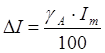
Similarly, the relative error is determined when measuring the current:
![]()
±δR =±3.33±5.6=±8.93%,
To determine the absolute error, as well as the limits of change of the actual value of the measured resistance R ratio should be used
![]()
![]()
![]()
4. The actual values of the measured resistance are within:
Rx -∆R≤Rx ≤Rx +∆R,
2.05≤R x ≤2.45
Task 3. Measurement of magnetic quantities
Magnetic measurements are an integral part of all electrical measuring technology. Wherein specific gravity magnetic measurements among others is continuously increasing. This is explained by the increasing use of magnetic phenomena in science and technology, a significant increase in the production of ferromagnetic materials (FMM) and their use in electrical devices, instruments and automation.
The classification of magnetic measurement methods is based on the physical essence of the phenomena used for the measurement process, i.e. conversion of a magnetic quantity into an electrical signal.
In this regard, there are induction methods for measuring magnetic quantities; methods based on the interaction of two magnetic fields; influence-based methods magnetic field on physical properties substances.
Methods for measuring magnetic quantities underlie the testing of magnetic materials. All ferromagnetic materials are divided into hard magnetic (MTM) and soft magnetic (MMM). The former are used as sources of permanent magnetic fields (PM permanent magnets). To date, three areas of testing have developed for them: the study of the properties of MTM, the production control of MTM samples, and the production control of permanent magnets. When studying the properties of MTM, it is necessary to obtain sufficiently complete information about the properties of the material: the initial magnetization curve, the limiting magnetic hysteresis loop, return curves for various points of the demagnetizing section, etc. The measurement of induction is usually carried out by induction and galvanomagnetic converters. The measurement of field strength usually comes down to measuring the current in magnetizing devices or obtaining information about the tangential component of the field strength from inductive or galvanomagnetic converters. MTM remagnetization can be carried out by a constant and an alternating field. When a material is magnetized by a constant field, static characteristics are obtained. With a continuous cyclic change in the field, dynamic characteristics are obtained, which in the infra-low frequency range of magnetization reversal can be approximated to static ones with the required accuracy.
To ensure the correctness of the MTM production process and the corresponding correction of the technological regime, the most important individual material parameters are controlled, in particular, the coercive force Hc. The algorithm for obtaining Hc is reduced to fixing zero values of magnetic induction or magnetization and reading the field strength.
At the heart of the classification features of the control of permanent magnets are the type of controlled parameters, the method of obtaining information. Distinguish control by magnetic flux in a system close to the working one; control over the demagnetizing section. According to the method of obtaining output information, devices with a direct reading and a differential measurement method are distinguished - obtaining information in the form of a difference in the characteristics of the exemplary and tested PM.
Magnetically soft materials are characterized by magnetic parameters measured in constant and alternating fields. The main measured characteristics in constant fields for MMM are: the main magnetization curve, the limiting hysteresis loop and its parameters (Br, Hc), initial and maximum magnetic permeability. GOST 8.377-80 establishes the ballast method for studying material properties as the main one. At present, in connection with the development by industry of unified electronic devices for wide application, the method of a continuous slowly changing field has become widespread.
In alternating fields, the main characteristics of MMM are the main dynamic magnetization curve, dynamic hysteresis loop, complex magnetic permeability and specific losses. In addition, depending on the frequency range of the test, there are a number of determined characteristics and parameters. The most frequent MMM tests are in the frequency range of 50 Hz - 10 kHz. The main test methods in this frequency range are: induction using an ammeter, voltmeter, wattmeter; induction using phase-sensitive devices (ferrometric); induction using an AC potentiometer; induction using ferrogaf (oscilloscope); induction using stroboscopic converters; parametric (bridge).
Induction methods are characterized by the measurement of the EMF induced in the measuring coils. The use of an ammeter and a voltmeter makes it possible to determine the dynamic relative permeability. Being the simplest, this measurement method has a large error (up to 10%) and does not provide the ability to determine losses in samples. The use of a wattmeter is standardized for the determination of losses in MMM samples.
The advantages of the wattmeter method are simplicity and high productivity, relatively small measurement error for industrial tests (5 - 8%), wide frequency range tests (up to 10 kHz). The disadvantages include a small amount of information and an increase in the error during magnetization reversal to an induction of more than 1.2 T due to the deviation of the shape of the curve from a sinusoidal one.
The ferrometric measurement method is based on the determination of the instantaneous values of periodic non-sinusoidal quantities using phase-sensitive devices. The relationship between the average value of the derivative of the function and the instantaneous value of the function itself is here the basis for the use of inertial devices for recording the dynamic characteristics of the MMM.
The advantages of the ferrometric method of measurement include: low error (2 - 5%); the ability to determine a large number of magnetic characteristics, including the calculation of losses. The disadvantages of this method are the limited size of the samples and the frequency range; duration of the process of measurements and processing of results; relatively high cost of devices.
The oscilloscope method is used to measure and visually observe the main dynamic magnetization curve, a family of symmetrical hysteresis loops, losses in samples at frequencies from 50 to 500 Hz. The disadvantages of the method include the need for measurements on the oscilloscope screen, which is associated with an increase in objective and subjective reading errors.
The most accurate of the MMM induction test methods is potentiometric, based on the measurement of signals proportional to B and H using alternating current potentiometers. This method determines the dependence of magnetic induction on the strength of the magnetic field, the components of the complex magnetic permeability, and the total loss. The advantages of the method are high measurement accuracy and a wide range of measured values. The disadvantages include: the duration of the measurement process, the high cost of the equipment used and its complexity.
The essence of the stroboscopic measurement method lies in the fact that the investigated periodically changing signals of arbitrary shape are multiplied by the so-called strobe pulse. In this case, the multiplication in each subsequent period occurs with a shift in time by a certain interval (reading step) relative to the previous one. As a result, it is possible to perform and then reproduce the reading of the entire period of the signal under study point by point. This makes it possible, like the ferrometric method, to use inertial self-recording and digital printing devices for recording rapidly changing processes. The main advantage of the stroboscopic method of measurement is the possibility of obtaining documentary information about the characteristics of the FMM in the process of magnetization reversal of the latter.
The parametric method for testing magnetic materials is to determine the inductance and resistance of the coil with the tested magnetic circuit by balancing the bridge circuit. Basically, this method is intended to determine the characteristics in the region of weak fields. Its advantages are: high measurement accuracy, wide frequency range of testing. The disadvantages include: the dependence of the measurement results on inductive and capacitive interference created by the elements of the measurement circuit; increase in error at low test frequencies; the complexity and duration of the testing process. There are other methods for testing MMM in the dynamic mode of magnetization reversal, however, the technical and operational characteristics of devices based on them are not effective in mass testing.