Big encyclopedia of oil and gas. Safety clutches
These couplings serve to protect machine parts from the effects of overloads: they separate the shafts when the torque increases above the permissible value.
According to the principle of operation, couplings are distinguished: with a collapsing element; spring-cam; friction.
4.I.I. Couplings with collapsing element
The safety elements of these couplings most often work in shear and in this case are made in the fort of cylindrical pins or in the form of parallel keys. These couplings are simple in design, which led to their wide distribution.
Figure 4.1 (Table 4.1) shows a coupling with a shear pin according to the machine tool normal R 95-1. Both coupling halves are located on the shaft. One half-coupling is connected to the shaft with a key, the other half-coupling sits freely on it, being connected by a key to the part located on its elongated hub.
Rice. 4.1 Coupling with shear pin
The rotation is communicated to the coupling halves through a cylindrical pin 4 located in bushings I and 2. To increase the durability, bushings I and 2 are made of 40X steel with subsequent heat treatment to a hardness of HRC 50...60. When overloaded, the pin is cut off, and the coupling halves freely rotate relative to each other. To facilitate the replacement of the pin on the outer surface of the coupling halves, risks are applied, when aligned, the axes of the holes of the bushings I and 2 coincide.
The pins are made of steel grades U8A, U10A or 40,45,50,
Elements of shear couplings are shown in Fig.42 (Table 4.1).
4.1.2. Friction clutches
These couplings are used for frequent short-term overloads; mainly under impact loads and significant angular velocities and transmit torque due to friction forces.
In Fig.4.2. the safety friction clutch is shown in accordance with GOST 15622-70, and in Table 4.2 its main dimensions and parameters are given.
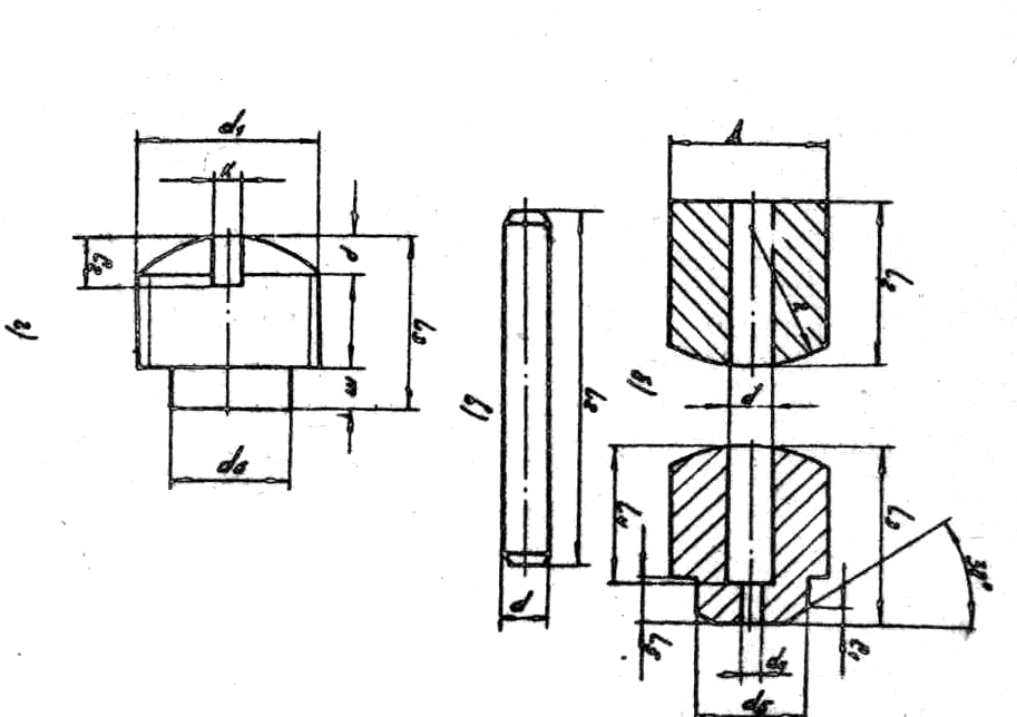
Fig.4.2 Elements of shear couplings
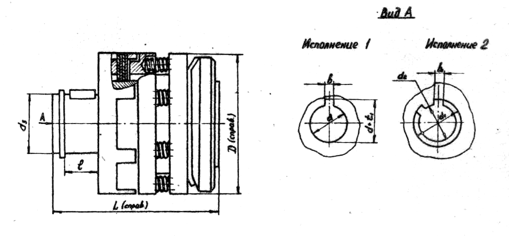
Rice. 4.2 Friction clutch
Table 4.2
Dimensions and parameters of the safety friction clutch (Fig. 4.2)
|
Coupling designation |
[M k ] kgfm |
Dimensions in mm |
|||||||||||
|
Previous off by A |
Landing holes execution1 execution2 | ||||||||||||
An example of a symbol for a coupling with an outer diameter D=50mm and a bore diameter for a shaft d=12mm, version 1: Coupling 1-5012 GOST15622-70
Bore diameter for splined shaft d 2 =11mm, version 2: Coupling 2-5011 GOST 15622-70.
OCHRYAN 1 IHI CHI (ii>767426
INVENTIONS
Union of Soviet
Socialist
5Ъrenewable kwmitt
USSR for Affairs of Acquisitions and Discoveries (53) UDC 621.825. .5 (088.8) Published 09/30/80 Bulletin No. 36
Yu. I. Ermishin and M. I. Granovsky (7I) Applicant (54) SAFETY FRICTION
The invention relates to the field of mechanical engineering.
Known safety friction clutch containing two friction half-clutches clamped by an adjustable spring between the thrust and pressure disks, between
5 with balls (11.
When overloaded, the thrust disk, overcoming
10 friction forces, rotates, and the balls, rolling over the end surfaces of the pressure and thrust disks, create an axial force, . unloading friction discs.
A safety friction clutch is also known, comprising a housing with spring-loaded friction discs placed between the thrust cup and the pressure disc, as well as a wringing unit made in the form of a clip installed in the thrust cup, a ring and rolling elements (2) placed in their end recesses. This clutch is the closest to the invention in terms of technical essence and the effect achieved.
Drawback indicated. couplings is that with a long-acting limiting moment when the driven body stops, the rollers of the wringing unit repeatedly leave the recesses and, rolling around the ends of the cage and rings, enter the recesses again, as a result of which the friction disks close and soften. This causes a dynamic shock load on the discs and through them on the entire mechanism. The bevels in the corners and the rollers themselves quickly fail, and scuffing is possible on the friction discs. Coupling heating is inevitable. These factors quickly lead to failure of the coupling. To avoid them, it is necessary to open the clutch when a limiting torque occurs.
The aim of the invention is to increase the reliability and service life of the clutch by ensuring the complete opening of the friction discs.
Gem of the invention is achieved by the fact that the clutch is equipped with fingers fixed in the cage, installed with the possibility of interacting with the pressure disk, while the ring
3 76 tso is fixed on the body, and the clip with the fingers is placed in the thrust cup with the possibility of axial movement.
The clutch can be provided with retainers installed in the thrust cup, spring-loaded in the rational direction, associated with the pressure plate and having grooves.
The clutch can be equipped with a retainer return assembly mounted in the thrust cup, made in the form of satellite bevel gears and a conical wheel with curved protrusions located in the grooves of the retainers engaged with them.
The clutch can be equipped with adjusting screws placed on the pressure plate, and there are gaps between them and the fingers. Fig. 1 shows the clutch, top view; in fig. 2 - section A-A in Fig. 1; on fig, 3— section B-B in fig. 2.
The clutch contains a housing 1 mounted on. shaft 2, thrust cup 3 mounted on shaft 4; friction disks 5, placed in the housing 1 and thrust cup 3; clamping disk 6, connected to the thrust cup 3 by studs 7, nuts 8 and pressed by springs 9; squeezing unit made in the form of a holder 10 and a ring 11, on which there are recesses 12 of variable depth and running tracks 13 for balls 14 installed in the separator 15. pressure plate 6, the gap is regulated by screws 17 placed on the pressure plate 6 opposite the fingers 16.
A bushing is mounted on the thrust glass 3
18 and cover 19, spring-loaded retainers
20 and knot; the return of the clamps 20, containing a bevel gear in the form of a bevel 21 wheel, which is coaxially installed in the sleeve 18 with the possibility of rotation, and satellite gears 22, which are installed in the sleeve 18 radially and rest on the nuts 23. Each of their clamps 20 has two grooves 24 and 25.
In the groove 24:, a leaf spring 26 is installed, which presses the latch 20 against the pressure disk
6, in the groove 25 there is a curvilinear protrusion
27 wheels 21 with a gap equal to the stroke of the latch 20. A stop is also installed in the sleeve 18
28, limiting the rotation of the bevel wheel 21 within the curvilinear protrusion 27, the satellite gears 22 are equipped with internal hexagons 29.
The leading link in the proposed coupling can be either a body 1, TRK and a thrust sleeve 3. Below is a description of the work
7426 4 couplings, when the body 1 is the leading link, the torque from the body 1 through the friction discs 5 is transmitted to the thrust cup 3. If the torque increases to such a value that the clamped friction discs 5 cannot transmit it, i.e. the thrust cup 3 slows down or stands up, then the body 1 together with the ring 11 will turn relative to
12 and squeeze the clip 10 together with. fingers 16, selecting the gap between them and the adjusting screws 17. The fingers 16 will press the pressure plate 6, overcoming the compression of the springs 9, and the clutch will open. The pressed pressure plate "to 6 releases the clamps 20, which, under the action of the springs 26, will extend and fix the pressure plate 6. The clutch will remain in the open position, the body 1 with the ring 11 - in rotation, the balls 14 will roll along the treadmills 13, slipping. indentation 12 i. without compressing the friction discs 5. After disconnecting the wire and eliminating the cause of the occurrence of the limiting moment, the clutch is brought into working position, unlocking the pressure plate 6. To do this, one of the satellite gears 22 is turned by the internal hexagon 29, while the bevel gear 21 rotates and the curvilinear protrusions 27 sink the clamps 20, compressing the springs 26. Released pressure plate 6 under the action of the force of the springs
9 presses on fingers 16 and presses clip
ll to the balls 14, which, when turning the body 1, rolling along the treadmills 1-3, fall into the recesses 12, after which the pressure disk 6 compresses the friction discs 5. ator 20.
The clutch is in working position.
The proposed implementation of the clutch provides opening it when the limit torque is reached. This allows you to use
45 friction clutches of this type in devices with a sharp and prolonged increase in torque. Such, for example, are the operating conditions of couplings in chip crushers during hits;
I in the last non-crushable bodies, the use of couplings
50 of the proposed type makes it possible to avoid breakage of couplings and chip-punching rolls and the accumulation of unground chips, and reduces the cost of equipment repairs.
Claim
1. Safety friction clutch: a clutch containing a housing with spring-loaded friction discs 5 767426 6 placed between the thrust discs. 2, characterized by a cup and a pressure plate, and also by the fact that it is equipped with a return assembly of the clamps, mounted in a thrust cup, made in the form of a mounting cup, a clip, ring, and filled in the form of bevel gears placed in their end recesses of the bodies 5 litas and being in rolling engagement with them, characterized in that that, a wheel with curved ledges, in order to increase the service life and reliably, located in the grooves of the clamps.
l ti by ensuring complete opening of the friction discs, it is equipped with fixed - 4. The clutch according to claims 1 - 3, which differs in the cage with fingers installed with an 10 with the fact that it is equipped with adjusting screws placed on the possibility of interaction with the pressure disk, the pressure disk, while the ring is fixed on the body, and between them and the fingers there is a gap. clip with fingers, placed in a thrust cup with the possibility of axial movement. L., 1973, p. 286, fig. 204.
I o in the radial direction, connected with a pressure disk and having grooves. class F 16 0 7/02, 1965 (prototype).
Compiled by O. Logvinova
Editor T. Morozova Techred K. Gavron Proofreader O, Bmaic, I Order 7168/32 Circulation 1095. Signature
VNIIPI of the USSR State Committee for Invention and oTKpbITHfl
113035, Moscow, Zh-35, Raushskaya nab., 4/5
Branch of PPP "Patent", r. Uzhhorod, st. Design, 4
24 November 2011 General information
The working process of many machines and mechanisms is dynamic in nature, accompanied by short-term (peak) load increases. In addition, an increase in the load can be caused by abnormal situations in the operation of the machine: a cessation of lubrication, clogging of the working parts, jamming, etc. Calculation of mechanisms for such maximum loads would lead to unnecessary weight and increase in the cost of the machine. Therefore, design is often carried out on the basis of nominal loads, and safety devices are used to prevent damage to parts during overloads. The functions of the safety link can also be performed by drive elements that allow slippage. So, in hydraulic drives, overloads are prevented by safety valves.
When transmitting torque between the shafts, safety (overload) clutches are used to protect against overloads. Sometimes they are also called torque limit clutches. They are installed in percussion machines; in machines that process a heterogeneous environment; in automatic machines and devices; in branching chains of kinematic chains of machines that transmit a small part of the power of the drive motor (drives for the supply of metal-cutting machines). Since safety clutches cannot eliminate the resulting shaft misalignments, they are often combined with compensating clutches.
Safety clutches according to the principle of operation, they are divided into: couplings with a collapsing element (not considered); friction ( rice. 1, a); spring-cam ( rice. 1, b); magnetic ( rice. 1, in). Spring-cam clutches have a number of varieties in which the cams are replaced by balls or rollers.
Friction clutches (Fig. 1, a) are the simplest in design. They are used for frequent short-term overloads, mainly shock action.
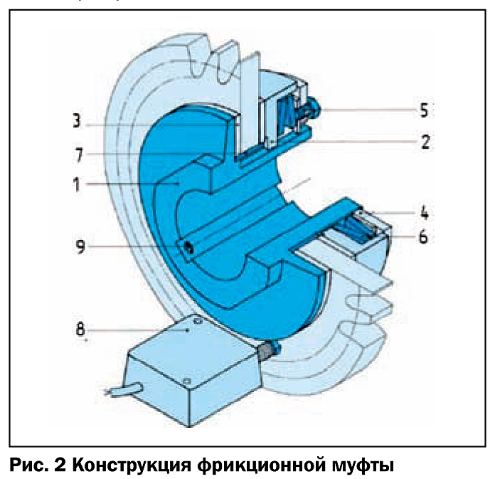
Friction clutch ( rice. 2) consists of a hub 1 , movable pressure plate 2 , friction linings 3 (asbestos-free!), adjusting nut 4 , locking screw 5 , Belleville springs 6 , plain bearing (sleeve) 7 , rotation encoder 8 (optional), lock screw 9 . Either standardized sprockets or pulleys or a flange are installed between the friction linings. The principle of operation of such a clutch is simple: Belleville springs create an axial force through the pressure ring, pressing the friction linings against the hub and flange (sprocket). When the current moment exceeds the moment of friction, the flange (asterisk) scrolls along the sleeve, which is a plain bearing. By changing the number and relative position of the disc springs, manufacturers get couplings with different transmitted torques. The use of a rotation sensor allows you to control the slippage time of the clutch and reduces the risk of damage.
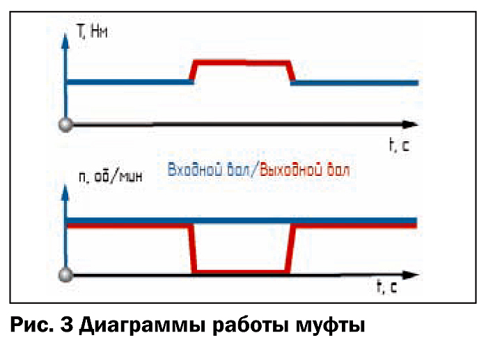
When overloaded ( rice. 3) the clutch slips and the rotation of the output shaft stops. The shaft connection is restored automatically without stopping the transmission of torque during slippage.
Instead of a plain bearing in couplings, a needle bearing is often installed. The use of a rolling bearing is justified with frequent coupling operations, at high sliding speeds, with large radial loads and with high requirements for the accuracy of the relative position of the shaft and the drive element (for example, when installing a gear wheel).
Manufacturers (companies KTR, Mayr, Ringspann) offer couplings with a range of transmitted torque T=2…50,000 Nm with a shaft diameter d=20…200 mm, respectively. An important parameter is the maximum allowable relative slip speed n s , min -1 . As the size of the clutch increases, the speed decreases. So, for a clutch with a shaft diameter d=20 mm, the allowable sliding speed for t S =1 s can reach n S = 8 500 min -1 , and for d=200 mm it decreases to n S = 700 min -1 .
Spring-cam safety clutches ( rice. 1, b) differ from friction clutches increased accuracy tripping, because the elastic properties of the springs are more stable than the coefficient of friction of the friction elements. The advantage of spring-cam couplings of special designs is also the absence of backlash and high torsional rigidity, which is very important in feedback drives (servo drives). However, at high speeds, such couplings are not used, because. subject to repeated overloads due to repeated self-switching. The maximum transmitted moments for these clutches are also lower than for friction clutches.
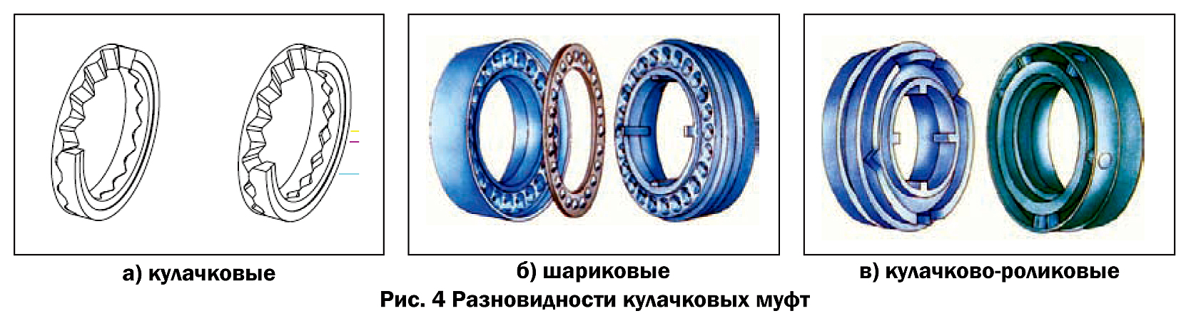
Spring-cam clutches are divided into cam ( rice. 4, a), ball ( rice. 4, b) and cam-roller ( rice. 4, in). In cam clutches, the working surfaces of the cams are made not flat, but made along a helical line. The processing of such surfaces is technologically complex. Therefore, ball couplings, which are easier to manufacture, are most widely used. In them, the cams are replaced by balls, and sliding friction is partially replaced by rolling friction. Cam and roller clutches use radially mounted rollers that mate with mating grooves.
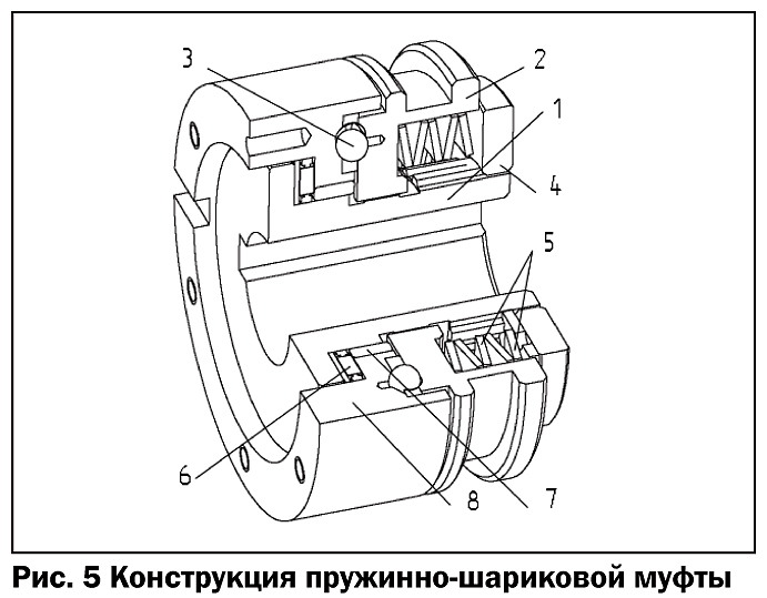
Spring-loaded ball clutch ( rice. 5) consists of a hub 1 , movable pressure plate 2 , clips with balls 3 , adjusting nut 4 , Belleville springs 5 ,thrust needle bearing 6 , plain bearing 7 and outlet flange 8 . The principle of operation of such a clutch is as follows: Belleville springs create an axial force through the pressure ring, pressing the balls against the sockets in the hub and flange ( rice. 4, b); when the current moment exceeds the permissible value, the balls leave the sockets and the transmission of rotation stops.
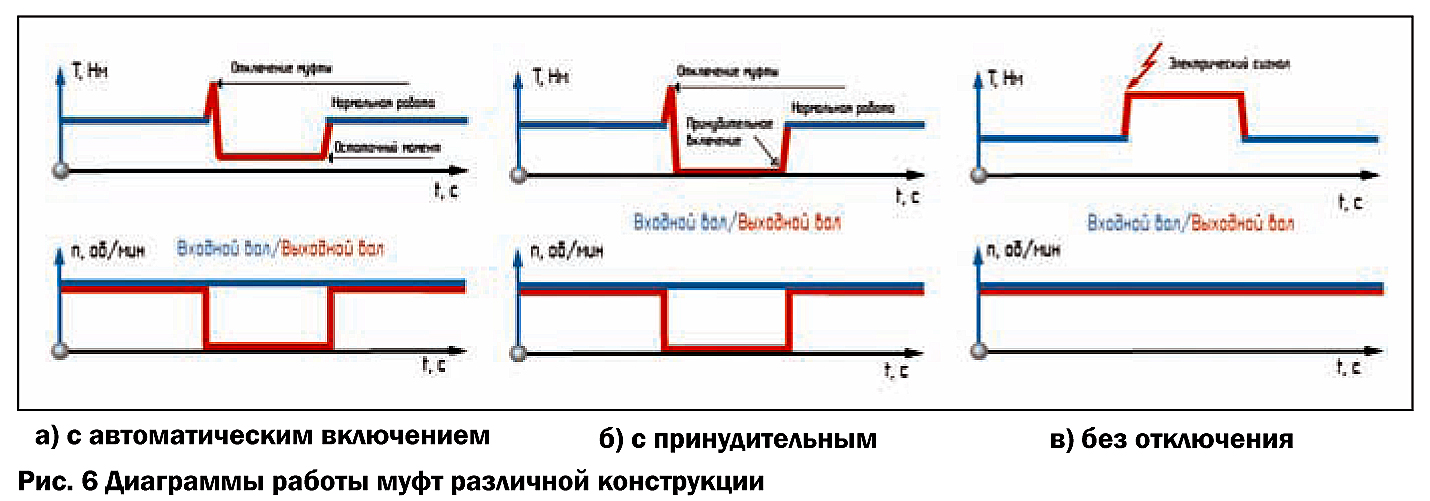
Unlike friction spring-ball clutches have various options restoration of the shaft connection ( rice. 6). When the clutch is actuated, shown in fig. 5 , the rotation of the output shaft stops, however, the residual torque is transmitted to it ( rice. 6, a). The clutch is switched on automatically after the termination of the overload and the rotation of the coupling halves by an integer number of angular steps of the balls.
If a locking mechanism is added to the clutch design between the movable disk and the spring block ( rice. 7), which closes the movable coupling half when actuated, then the restoration of rotation is possible only manually or by an external actuator. A diagram of a clutch with a similar mechanism is shown in rice. 6b.
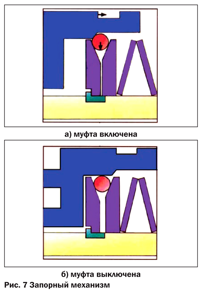
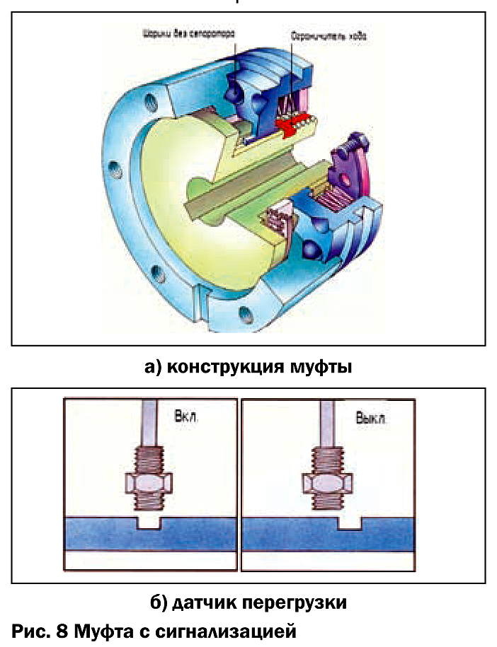
In some designs, such as hoisting machines, interruption of the torque transmission is unacceptable, and an alarm is required in the event of an overload. Then in the basic design of the coupling ( rice. 5) introduce the travel limiter of the movable disk (Fig. . 8, a). When the clutch is actuated, the movable disc moves away from the stationary one until it stops at the limiter. The coupling withstands 4 times the load of the nominal value. When moving, a contactless ( rice. 8, b) or contact sensor. A diagram of the operation of such a clutch is shown in fig 6, c. It should be noted that the trip sensor can be installed in other types of couplings, generating a trip signal.
In the designs of some machines and units, it is necessary to maintain the exact mutual angular position of the driving and driven links. On the basis of the mutual angular position of the shafts, the couplings are divided into ratchet and synchronous. Coupling shown on rice. 5, has a ratchet design.
In a ratchet clutch, after the overload action is terminated, the balls occupy the next free position, and, consequently, the mutual position of the shafts is arbitrary.
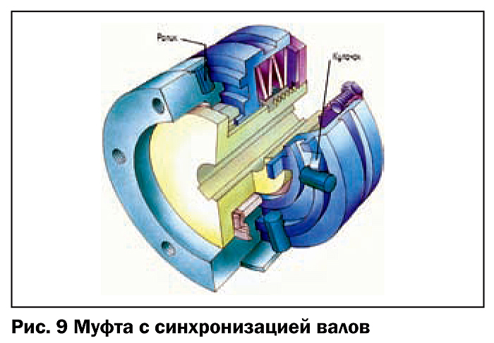
On rice. 9 a spring-loaded cam-roller clutch is presented, which only reconnects when the coupling halves are rotated through 360° (45°, 60°, 90° or 180°). This is a synchronous clutch. The principle of operation is similar to the considered spring-ball clutch. A strictly defined mutual position of the shafts is achieved by the uneven angular position of the cams and return rollers ( rice. 4, in). Synchronous design can also be provided with spring-loaded ball couplings ( rice. 11, b, 12, b, 13, b).
Manufacturers of spring-ball (cam) clutches (firms KTR, Mayr, Ringspann) offer couplings with a range of transmitted torque T=2.5…6,000 Nm with a shaft diameter d=20…150 mm, respectively. For a coupling with a shaft diameter of d=20 mm, the allowable sliding speed for t S =1 s is n S = 4300 min -1 , and for d=150 mm it is reduced to n S =600 min -1 .
In modern machines, systems with a feedback sensor (servo drives) are widely used. Most often, the feedback sensor is installed on the engine (servomotor), and the movements of the driven mechanism are monitored by the number of engine revolutions. For example, it is on this principle that most CNC machines work. However, if the elements located in the kinematic chain after the engine (couplings, gearboxes, etc.) have low torsional rigidity and (or) backlash, then when the load is reversed in the displacement calculation system, a discrepancy occurs between the number of revolutions of the engine shaft (taking into account gear ratios) and the real values.
To solve this problem, manufacturers offer safety clutches with no backlash ( rice. 11, 12, 13). The absence of backlash is achieved by increasing the accuracy of manufacturing the clutch elements, and, above all, the torque transmission unit. Uniform load distribution between the balls ensures high torsional rigidity. On rice. 10, a shows a comparative relationship between the torque and twist angle of a standard coupling and a coupling with no backlash.
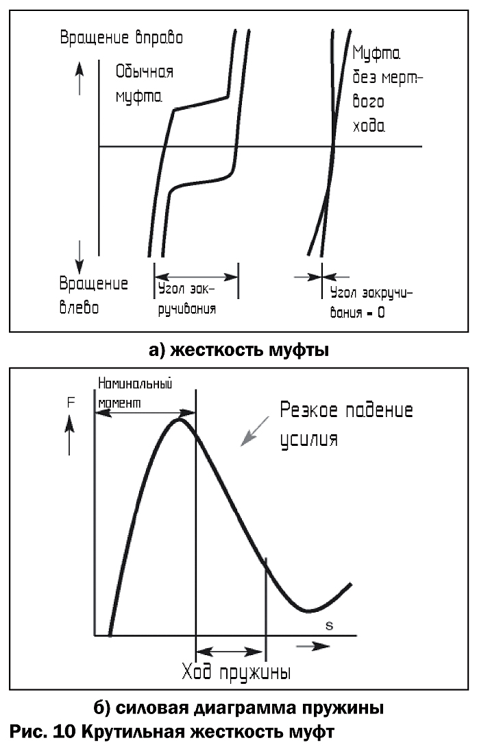
For precision couplings, a belleville spring is often selected so that the operating range of travel falls on the downward branch of the spring force diagram ( rice. 10b). This allows you to increase the speed and accuracy of the clutch.
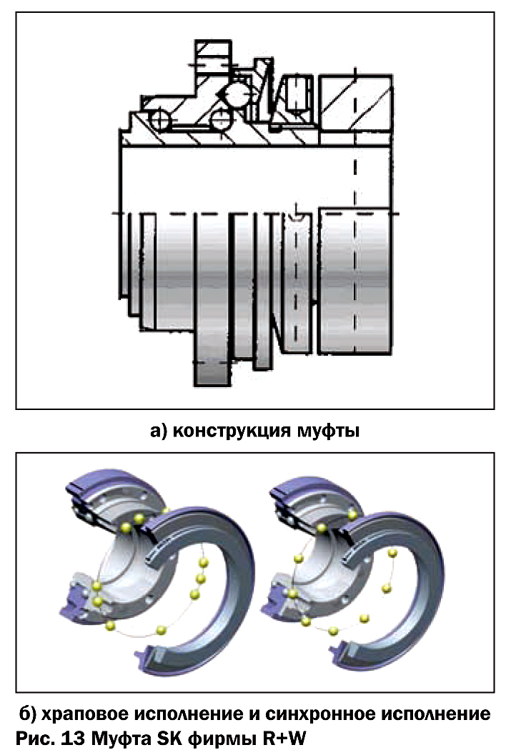
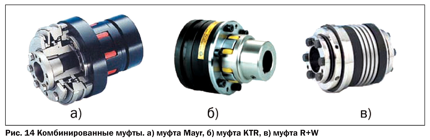
By design and principle of operation, the couplings with no backlash are similar to the spring-loaded ball couplings described above. On rice. 11 - 13 Couplings of firms are presented Mayr, KTR and R+W with torque transmission units. Couplings have both ratchet and synchronous designs; versions with a locking mechanism; performance without interrupting the transmission of torque from the generation of an electrical signal; can be equipped with a trip sensor.
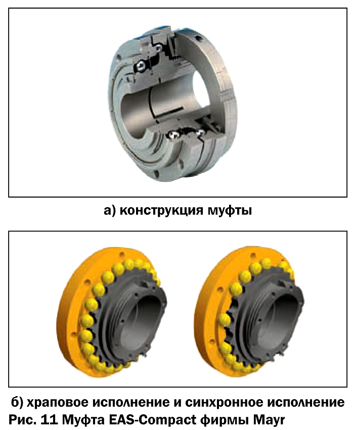
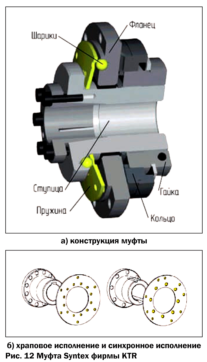
Consider the original design solutions that distinguish backlash-free couplings various manufacturers. In addition to the requirements for accuracy and lack of backlash in servo drives, they strive to reduce the mass moment of inertia (mass) of the driven parts. Reducing the weight reduces the power requirements of an expensive servomotor. In the design of the KTR Syntex coupling (Fig. 12), the torque is transmitted through a special Belleville spring with seats for the balls. Combining the functions of the pressure spring and the movable flange reduces the weight of the torque transmission unit. On the other hand, the manufacturing technology of a special Belleville spring becomes more complicated.
In almost all couplings, in order to increase the running accuracy of the output flange and reduce the overall dimensions of the assembly, the plain bearing is changed to a rolling bearing. In the design of the company's couplings R+W (rice. 13) integrated bearings are used. This reduces the mass of the bearing assembly and the size of the output flange. However, the production technology of the coupling becomes more complicated (the need to make raceways, assembly complexity, etc.)
In addition to the keyed connection, friction clamping hubs are widely used in couplings ( rice. 11 - 13). Their use facilitates assembly with a guaranteed absence of gaps in the coupling-shaft connection. We have already written about the types of clamping couplings and the features of their application (RITM No. 8, 2008)
Safety couplings do not compensate for shaft misalignment. For this, there are compensating couplings. If it is necessary to install two types of clutches in the mechanism, you can purchase a combined clutch ( rice. 14). In the compensating part of such a coupling, couplings are used: elastic with an elastomeric sprocket ( rice. 14, a, b), bellows ( rice. 14, in), gear, disk.
Manufacturers of ball-spring couplings with no backlash offer couplings with a range of transmitted torque T=15…2,800 Nm with a shaft diameter d=4…100 mm, respectively. For a coupling with a shaft diameter of d=4 mm, the allowable sliding speed is n S = 4,000 min -1 , and for d=100 mm it is reduced to n S =250 min -1 .
long slip in friction clutches would lead to high wear of the friction surfaces. Therefore, in cases where long-term sliding is necessary, couplings based on the use of liquid or magnetic interaction forces as a transmission link are used. On rice. 1, V the magnetic coupling on permanent magnets is presented. The coupling consists of a hub with permanent magnets; output flange resting on a rolling bearing; a sleeve with a magnet screwed onto the output flange, a locking screw. By screwing or unscrewing the sleeve, you can change the transmitted moment. There are no rubbing elements in the clutch.
The clutch operation diagram is shown on rice. 15. As can be seen from the figure, a constant torque always acts on the output shaft, and the output shaft revolutions fall when overloaded. When the clutch slips, heat is generated. The allowable sliding time and speed depend on the thermal conditions of the coupling.
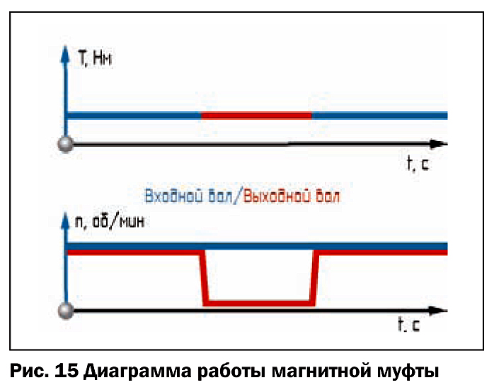
Firm Mayr, presented on our market, offers magnetic couplings with a range of transmitted torque T = 0.1 ... 6 Nm with a shaft diameter of d = 10 ... 38 mm, respectively. For a coupling with a shaft diameter of d=10 mm, the allowable sliding speed is n S = 4000 min -1 , and for d=38 mm it is reduced to n S =3000 min -1 . The scope of such couplings is limited (test equipment, control mechanisms, etc.).
Installation of couplings
In the kinematic chain, it is recommended to place the safety clutch directly on the shaft that drives the actuator ( rice. 16). In this case, all mechanisms in the circuit are protected from overloads.
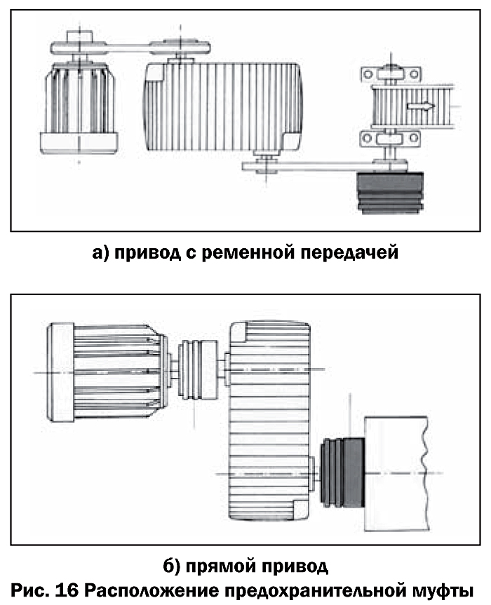
However, in most cases, the torque on the actuator is significantly higher than on the motor. Accordingly, the size and price of the coupling increases. On rice. 16b shows an alternative placement of the coupling. In this case, the gearbox must withstand peak overloads.
Very often, safety clutches are combined with a pulley (sprocket) of belt (chain) drives or a compensating clutch. When designing an assembly with a safety clutch, it should be remembered that not all clutches require the installation of transmission elements directly on the output flange. On rice. 17, and the installation of a safety clutch on the output shaft of an electric motor with a belt drive pulley is shown. The pulley is mounted on a separate rolling bearing. On rice. 17b the design of the safety clutch with a long hub is presented, designed to install a pair of sprocket bearings of a three-row chain.
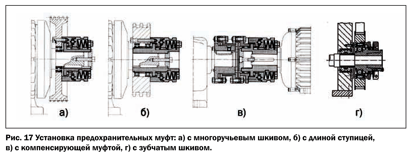
In the case of the combination coupling shown in rice. 17, in, the leading coupling half of the compensating part is mounted on a needle bearing. Couplings on rice. 2 and 17, d allow you to install an asterisk or toothed belt pulley without additional supports.
Calculation sequence
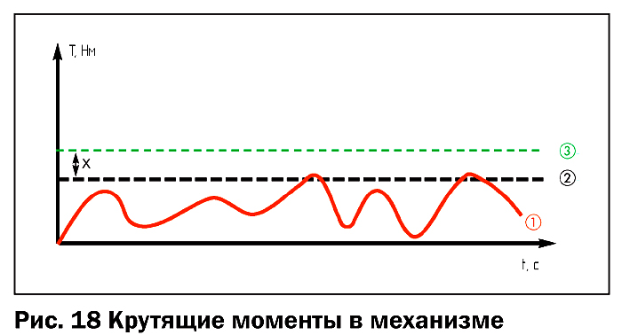
On rice. 18 under the number 1 a graph of the actual operating moment in an arbitrary mechanism is presented. Numeric 2 the limit of the maximum value of this moment is indicated. The nominal moment of the coupling T N, Nm is recommended to be taken 30 ... 50% more than the maximum moment that occurs during operation (indicated by the number 3 ).
Conclusion
Incorporating safety clutches into the design reduces the cost of the machine (due to downsizing) and the cost of operation (due to increased reliability). The designs of the couplings offered on the market are diverse and can satisfy any designer's requirements. It remains only to choose and remember that " The only problem with choice is that it exists.».
Mikhail Grankin
RITM magazine, February 2009
As safety (slip) clutches, various friction and cam clutches, as well as clutches of a special design, can be used.
Friction clutches
In safety friction clutches, the disks are compressed under the action of a spring, the force of which is calculated so that when the torque increases above the permissible value, the disks begin to slip and, with the rotating leading part of the clutch, the driven part remains stationary.
Since the actual value of the friction coefficient can differ significantly from the calculated value, the moment at which the clutch operates can also fluctuate significantly.
Cam clutches
Cam slipping clutches with beveled mechanical cams are similar to the clutches used in the mechanisms discussed above, which open the kinematic chain with increasing torque. The difference lies in the fact that when the torque increases, the kinematic chain does not open and the clutch works like a ratchet, which causes increased clutch wear.
Rice. 13 Safety clutches
Ball Couplings
Of the numerous special designs of couplings, ball couplings are widely used. One of the variants of the ball coupling is shown in fig. 13a. The safety clutch connects gear 3 with disk 5. Communication is carried out using balls 4 located in the holes made in the body of gear 3. The balls also go into the holes of disk 5. They are pressed against the disk into balls by springs 6. The tension of the springs, and, accordingly, the amount of transmitted torque, is adjusted using nut 1, which moves plunger 2. When overloading the edges of the holes of disk 5, the balls and clutches are pressed but works like a ratchet.
The force of the springs can be determined in accordance with the method for calculating the cam clutches. elevation angle in this case is the angle between the tangent to the ball and the end plane of the disk 5.
Special couplings
Safety devices with shear pins and keys are used in cases where overloading is rare and occurs only in emergency conditions. As an example of a safety device with a shear pin, a normalized clutch is shown (Fig. 13, b). Hardened bushings 2 and 4 made of 40X steel are pressed into coupling halves 1 and 5. A shear pin 3 passes through the holes of the bushings, which is usually made of the most durable material. When overloaded, the pin is cut off and must be replaced with a new one.
By using a high strength material for the manufacture of the pin, the possibility of accidentally replacing a pin of low strength with a pin of higher strength is eliminated, which could lead to a breakdown of the machine's mechanisms.
- 829 views
Page 1
Safety clutches - with a collapsing element - a cylindrical pin (normal R95 - 1, normal SKB-3) or a parallel key; spring-cam (GOST 15620 - 70); spring-ball (GOST 15621 - 70); friction disk (GOST 15622 - 70); friction cone.
Safety clutches (Fig. 3.12) connect two shafts under normal operating conditions and break the kinematic chain when the load increases. A chain break can occur when a special element is destroyed, as well as as a result of slippage of mating and rubbing parts (for example, discs) or disengagement of the cams of two mating parts of the coupling.
Safety couplings (Fig. 5.16) of two welded coupling halves are installed in order to increase the operational reliability of gas pipelines with uncertainty in the welds and their imperfections.
Safety clutches stop the transmission of motion to the driven shaft if the moment of resistance on it exceeds the permissible value. They are designed to protect a certain part of the mechanism from overloads of a different nature. The action of the couplings is based in most cases on the slippage of one part of the coupling relative to the other due to the occurrence of a more than permissible torque on the driven shaft. The main types of construction: friction, spring-cam, spring-ball, spring-roller, shear pin clutches.
Safety clutches with movable pins (Fig. 3) have movable pin elements that, when overloaded, are displaced, overcoming the forces of the weapon. The disadvantage of such couplings is their bulky, especially when transferring large loads, and the impossibility of adjusting the axial force of the springs with the radial arrangement of the pins.
Safety clutches are used in mechanisms where significant overloads are possible, which can lead to breakage of individual parts of the machine, as well as to protect against inertial effects of significant masses that occur when the machine is started or its rapid braking.