Cutting ends and ledges. Design features of cutters. Cutting conditions for undercutting
Usually, the ends and ledges are cut on lathes with scoring cutters.
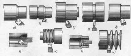
On fig. 137, a is shown cutting cutter. It has a long cutting edge 1, usually set at an angle of about 5 ° to the cut surface of the part, and a short cutting edge 2. This edge is strongly beveled so that you can bring the tip of the cutter closer to the center of the part when cutting it in the centers (Fig. 137, b, c).
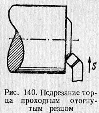
When trimming ends, shoulders and ledges that are not constrained by the center of the machine, cutters are used, shown in Fig. 138. These cutters can work with both longitudinal and transverse feeds. To cut ends or ledges in hard-to-reach places, for example, when you have to bring the cutter close to the cartridge, use bent cutting cutters (Fig. 139). For the same purposes, bent cutters are often used (Fig. 140), which are informed of the transverse feed.
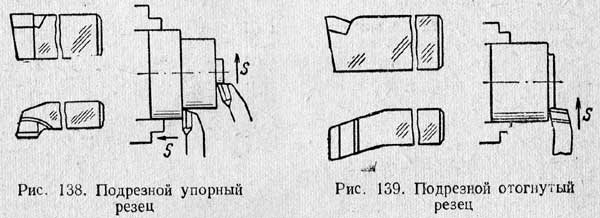
When trimming ends and ledges, the tip of the cutter must be set exactly to the height of the centers. If the cutter is set below the center, then an uncut ledge will remain in the middle of the solid end. A cutter set above the center may break.
Ledges of small height can also be cut with a scoring hard cutter with longitudinal feed simultaneously with turning a cylindrical surface (Fig. 138). The correct location of the ledge with this method of cutting depends entirely on the installation of the cutter, its cutting edge must be strictly perpendicular to the axis of the part.
The processing of ledges of great height is usually carried out in several passes, combining longitudinal with transverse feed. First, a scoring cutter set at an angle of 5° to the ledge surface is used to process a cylindrical section, while for each longitudinal pass a layer of 2-3 mm is removed. Then, with the same cutter, the ledge is trimmed with a feed directed from the center to the outer surface of the ledge.
2. Techniques for cutting ends and ledges
When trimming the ends and ledges, the parts are installed in the same ways as for longitudinal turning.
Trimming ends in centers. When cutting the ends of parts installed in the centers, it is recommended to install in tailstock so-called semi-center(see Fig. 137, b), which provides cutting of the entire end. It is even better to use center holes with a safety (double) cone (Fig. 137, c). The feed direction in both cases is from the periphery to the center.
Trimming the ends in the chuck. It is advisable to cut the ends of parts fixed in cartridges not with a scoring, but with a bent cutter through (see Fig. 140). The latter has a more massive cutting part, allowing higher cutting conditions.
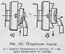
When cutting ends and high ledges, the feed direction can go from the outer surface to the center (Fig. 141, a) or from the center to the outer surface (Fig. 141, b). In the latter case, the force acting on the cutter tends to push its cutting edge away from the end face of the part. This results in a cleaner end surface than when working with a feed directed from the outer surface of the part to its center. However, this method of cutting ends and ledges does not allow checking the exact position of the end or ledge after a test chip relative to other surfaces of the part. Therefore, the above rule on the choice of the direction of the transverse feed sometimes has to be abandoned.
High performance working methods. When cutting a significant number of identical parts with ledges, longitudinal feed should be used in conjunction with a stop that limits the movement of the caliper (see Fig. 131).
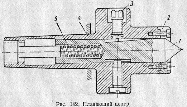
When it is required to withstand the lengths of individual steps, regardless of the depth of the center holes, they are successfully used floating centers(Fig. 142).
Such a center 1, mounted inside the housing 4, is inserted into the tapered hole of the headstock spindle. Spring 5 tends to press the center to the right and create contact between the center and the part.
The part installed in the centers, when the tailstock quill is pressed, is brought to a hardened stop 2 attached to the end of the body 4. After that, the floating center is locked with a bolt 3 for the duration of the processing of this part. When installing the next part, bolt 3 must be released.
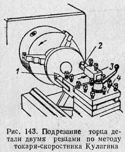
The speed turner Comrade Kulagin, when cutting the end of a part with a hole (see Fig. 143), uses two cutters 1 and 2 simultaneously. These cutters are fixed with the same overhang in a special holder 3, which in turn is fixed in the tool holder 4. Cutter 2 cuts end from the outer diameter, and cutter 2, installed in the tool holder with the cutting edge down, from the inner. Due to the simultaneous processing of two cutters, the length of processing, and consequently, the processing time, is reduced by 2 times. This method of cutting the end can be recommended for roughing, since it is difficult to obtain a smooth end without a ledge when two cutters work simultaneously.
Methods for measuring ends and ledges. The straightness of the end surface can be checked using a ruler (Fig. 144), which is applied to the end surface. If there is a gap, you can determine its size by eye or with a special measuring plate-probe.
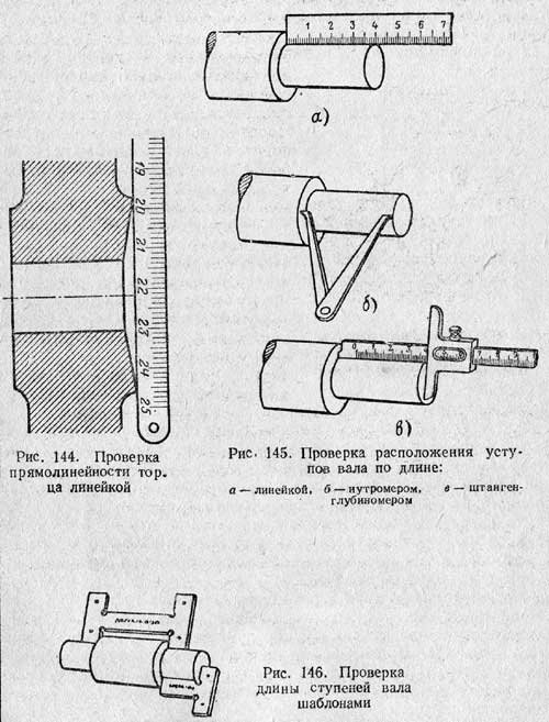
The correct location of the ledges along the length of the shaft is checked with a ruler (Fig. 145, a), an inside gauge (Fig. 145, b) or more precisely, a depth gauge (Fig. 145, c). For an accurate check a large number identical parts, it is recommended to use templates (Fig. 146).
3. Cutting conditions for undercutting
When cutting ends and ledges with transverse feed, the depth of cut is the thickness of the layer being removed, and the feed is the amount of movement of the cutter in the transverse direction per one revolution of the part.
When undercutting, the following cross feeds can be recommended:
for roughing- from 0.3 to 0.7 mm/rev at a cutting depth of 2 to 5 mm;
for finishing- from 0.1 to 3 mm/rev at a cutting depth of 0.7-1 mm.
When trimming the ends, the same cutting speed can be used as when machining the outer cylindrical surface, but it should be calculated by the larger diameter.
4. Marriage when cutting ends and ledges and measures to prevent it
When cutting ends and ledges, the following types of marriage are possible:
1) part of the surface of the end or ledge remained unprocessed;
2) incorrect location of the undercut end or ledge along the length of the part;
3) non-perpendicular location of the ledge to the axis of the part;
4) insufficient cleanliness of the surface of the end or ledge.
1. The marriage of the first type is obtained due to incorrect workpiece dimensions, small machining allowance, incorrect installation and inaccurate alignment of the part in the chuck, incorrect installation of the cutter along the length of the part or along the height of the centers.
Such a marriage is usually unrecoverable, but it can be prevented by checking the dimensions of the workpiece, increasing the machining allowance, checking the correct installation of the part and the cutter.
2. Incorrect location of the cut end or ledge along the length is obtained by inaccurate installation of the cutter or untimely shutdown of the self-propelled gun (with longitudinal feed), as well as by axial displacement of the part in the chuck as a result of its insufficiently strong fixing. If at the same time the boundary of the ledge is crossed, then a marriage of this kind is irreparable. You can prevent such a marriage by checking the installation of the cutters and the strength of the fastening of the part in the cartridge, as well as the timely shutdown of the self-propelled gun when working with longitudinal feed.
3. A non-perpendicular location of the end or ledge to the axis of the part when working with a transverse feed can result from inaccuracies in the caliper guides, as well as due to the pressing of the cutter due to its loose fastening in the tool holder, too small cutter section, carriage departure if it is not locked. When working with longitudinal feed, a common cause is incorrect cutter setting. Marriage of this type can be prevented by eliminating the listed causes.
4. Insufficient cleanliness of the surface of the end face or ledge is obtained as a result of overfeed, large overhang of the cutter, insufficiently strong fastening of the cutter or part, improper sharpening of the cutter, significant blunting of the cutter, high viscosity of the metal being processed, jitter of the carriage or parts of the caliper, jitter or runout of the spindle or chuck .
You can prevent such a marriage by timely elimination of the causes that cause it.
test questions 1. What are the design features of the scoring cutter?
2. How are scoring cutters installed?
3. What are the ways to cut ledges?
4. How is the cutter set for side feed shoulder cutting?
5. How is the trimming of the ends when installing parts in the centers?
6. How is the trimming of the ends when installing parts in the chuck? What kind of cutters are convenient to use?
7. Tell us about high-performance methods of work when cutting ledges, ends.
8. What is called the depth of cut when cutting the end?
9. How to check the correctness of the cut end?
10. Indicate the main types and causes of marriage when cutting ends and ledges; measures to prevent it.
Most turning operations are done with cutters. Among the main types, the cutting tool occupies a leading position in terms of frequency of use. They are made from special grades of steel of special hardness.
Purpose of cutting tool
Depending on the type of operation, the main types of incisors are used:
- threaded for external and internal cutting;
- through passage straight, bent and persistent;
- boring for blind and through holes;
- cutting.
Turning cutting tools are used to cut off a part from a small diameter rod and form grooves in the workpiece. They are cut with cutting tools for special purposes - grooving. The shape of the working head corresponds to the size and shape of the future groove. Often in one pass the groove right size fails to do. In several passes, they work with hard metals, as well as with a large groove width.
The length of the working area should be slightly more than half the diameter of the part being cut.
Types of designs of cutting tools:
- solid: machined from a single piece of metal. They are made of tool carbon steel, small ones are made of high-speed cutting steel. Not widely used in practice;
- with welded blades: a carbide or high speed blade is welded on the head. When welding them, it is important to follow the technology, otherwise cracks appear, the tool quickly collapses;
- with mechanical fixation of inserts: a cutting insert is inserted into the head of the tool and fastened mechanically. They are often used for mineral-ceramic cutting inserts.
Turning cutters can be left and right, straight or bent. The most common in practice are left bent and right straight.
Cutting blade design
Any turning tool consists of a body and a working head. The peculiarity of the cut-off is that its head is drawn, that is, its width should be less than the width of the body. The length of the edge should be such that it is convenient to cut off the blank. Cut-off cutters are subjected to a large load, because the rigidity of the functional part is small, and the removal of chips is difficult. The thickness of the heads is quite small, therefore, in order to maintain their strength, the angles take about 1 - 3 degrees (rear and in plan). Due to this shape, if the tool is incorrectly installed or dressed badly, friction increases significantly.
Therefore, during turning work, cutting tools with carbide tips often crumble, cutting edges are chipped, and soldering disappears.
The following zones are distinguished on the working head: the cutting edge (main and auxiliary), the top of the head, the front surface of the head and a pair of rear ones. The cutting edge is located along and sharpened in the form of a wedge. The purpose of the body or shank is to mount the tool in the handpiece.
High-quality cutting can only be done with a properly sharpened cutting tool. For the correct identification of angles, the following concepts are used:
- main plane: this is a surface aligned with the reference plane, parallel to the feed in the longitudinal and transverse planes;
- cutting plane: tangent to the surface of the workpiece, passes along the working edge.
The following angles must be met:
- rake angle: determines how easily the chips will be removed from the metal blank and how well it is cut;
- Major Clearance Angle: This is the angle between the surface of the cutter and the turning plane. The sharper it is, the stronger the back surface of the cutter rubs against the blank;
- taper angle: between the anterior and posterior main surfaces. The smaller it is, the easier it is to cut metal. However, the cutting surface wears out faster, crumbles.
To increase the reliability of fastening the working head with the holder, the plate with bevels is soldered into a tongue, which is made in the form of an angle. Due to this, the area of their fit increases, and the sides of the tongue do not allow the plate to move to the side under the action of forces that appear during the operation of the cutter.
In addition, the height of the head must exceed the length of the rod.
When cutting off the workpiece, the tool does not cut off the entire thickness of the material, since at a certain stage the part breaks off, leaving a piece of the rod in its middle. When it is necessary to finish the end part, the main working edge is sharpened at an angle of 75 - 80 degrees, in other cases this angle is 90 degrees.
In practice, turning tools are often used with a broken symmetrical working edge, sharpened at 60 - 80 degrees in plan. Thanks to this dressing, the tool enters the material more easily, chip removal is facilitated, and the likelihood of cutter withdrawal is reduced. For this, at an angle of 90 degrees, chamfers are selected on both sides at an angle of 45 degrees, up to 1.5 mm in size.
Installing the cutter
The tool is set at an angle of 90 degrees to the workpiece being processed, in its center. A difference of fractions of a millimeter leads to breakage of the cutter.
When turning brittle metals, the cutter is held at an angle of up to 10 degrees. Otherwise, the workpiece will break off faster than the torch reaches the center. When working with high-speed tools made of solid metal, it is necessary to observe the processing speed of no more than 30 m/minute. Tungsten carbide cutters operate at high speeds of up to 130 meters per minute.
Cut-off cutter inverted
Particularly difficult cutting work on amateur machines with low speed and with weak technical specifications. You can sharpen a standard cut-off cutter, but this work is long and painstaking, the tool will turn out to be quite fragile, requiring extreme accuracy in work.
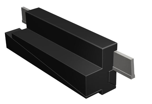
To solve this problem, the design of the inverted cut-off cutter was invented. These are tools with replaceable carbide steel inserts. They can be used for forward and reverse rotation. Moreover, the main mode for this tool is reverse rotation, when the chips are separated without hindrance, they are easy to remove from the work area, jamming occurs less frequently.
The design provides for adjustment of the cutter in height with the help of an insertable triangle and a T-shaped profile of the cutting plates. This shape reduces friction during penetration into the material. The kit usually comes with 4 - 5 options for cutting plates. They can be sharpened many times, as long as the length allows.
The large overhang of the cutting plate is very convenient, thanks to which thick workpieces can be cut, it is advisable to lubricate them during operation. The tool is good for sampling narrow grooves, especially at the points of contact between the planes.
Cutters are classified:
in the direction of feed - to the right and left (right incisors to lathe work when feeding from right to left, i.e. they move to the headstock of the machine);
according to the design of the head - into straight, bent and drawn (Figure 4);
Rice. 5.4. Incisors: a - straight, b - bent, c - drawn
by the type of tool material - from high-speed steel, hard alloy, etc.;
according to the method of manufacture - into solid and composite (when using expensive cutting materials, the cutters are made composite: the head is made of tool material, and the holder is made of structural carbon steel; composite cutters with hard alloy plates that are soldered or mechanically fastened are most widely used);
according to the cross section of the holder - into rectangular, round and square; by type of processing - for through-hole, scoring, cutting, slotted, boring, shaped, thread-cutting, etc. (Figure 5).
Rice. 5.5. Turning cutters for various types of processing:
a - external turning with a curved pass-through cutter,
b - external turning with a straight through cutter,
c - turning with cutting the ledge at a right angle,
g - cutting a groove,
e - turning the radius fillet,
e - boring holes,
g, h, i - threading external, internal and special
Basic rules for assigning cutter angles
Main relief angle , sharpened to reduce friction of the rear surface of the cutter on the cutting surface of the part. With its increase, the contact area between these surfaces and, accordingly, the friction force decreases. However, an increase in beyond certain values leads to a decrease in the taper angle , weakening of the cutting wedge of the cutter and, consequently, to a decrease in its strength. In turn, a decrease in the massiveness of the cutting wedge causes an increase in the cutting temperature and, accordingly, a decrease in the tool life.
Thus, the value of the main rear angle must simultaneously satisfy two conflicting conditions. Recommended angles are shown in Table 5.1.
Auxiliary back angle 1 is assigned from the same considerations and is usually equal to the angle or 1 ... 2 ° less.
Table 5.1
Cutter clearance angle values
with various types of processing
The main rake angle is sharpened to facilitate chip cutting. With its increase, plastic deformations of the cut layer and cutting forces decrease, and the movement of chips along the front surface is also facilitated. From this point of view, it is desirable to set the rake angle close to 45°. However, such an increase in the angle causes a decrease in the taper angle weakening the cutting wedge of the cutter and leads to the above-mentioned consequences.
In this regard, front angles close to 45° can be assigned only when processing materials with low strength properties. For materials with high strength properties, the largest rake angles are assigned. The following values of the main rake angles of cutters equipped with carbide inserts are recommended (table 5.2):
Table 5.2
Values of the main front angles of the incisors
with carbide inserts
Note: For HSS picks, the angles are increased by approximately 5°.
It is easy to see that the front angle > 0 leads to a weakening of the cutting wedge of the cutter. Therefore, in cases where the cutter experiences large dynamic loads, it is necessary to increase its strength. This is achieved by using negative rake angles (< 0). В результате увеличивается массивность режущего клина и изменяется характер деформаций, которые он испытывает: изгиб заменяется сжатием. Поэтому в случае обдирочного точения с большими глубинами резания и динамическими нагрузками на резец передние углы назначают отрицательными в пределах -5…-15°.
Entering angle significantly affects tool life and surface finish. With its increase, the massiveness of the cutting wedge decreases and the conditions for heat transfer from the main blade worsen. Therefore, from the point of view of resistance, it is desirable to set the angle small.
However, this is usually prevented by the configuration of the parts, which are most often stepped. In addition, at small angles , the forces increase R at and the vibrations in the machine-tool-tool-part (AIDS) system are amplified. Therefore, the use of small angles is possible only when turning parts with the same diameter with a rigid AIDS system. Under normal conditions, the entering angle is determined by the configuration of the parts and is equal to 45°, 60° or 90°.
Auxiliary lead angle 1 has the same effect on tool life and surface finish as the entering angle . Since the angle is assigned mainly on the basis of the tool life and the configuration of the part, we can assume that 1 has the main effect on the finish of the machined surface. The smaller the angle 1 , the lower the height of the microprofile roughness of the machined surface. Recommended values of this angle for roughing and finishing cutters are 10…15°. In cases where it is necessary to obtain a higher surface finish, this angle is reduced to 3 ... 5 °, and in some cases an auxiliary blade is sharpened 3 ... 5 mm long with an angle 1 = 0 (chisel by the innovator V. Kolesov).
The angle of inclination of the main blade has a significant impact on the direction of chip flow and on the tool life. It can be positive, negative, or zero (Figure 5.6).
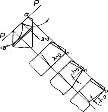
Rice. 5.6. Influence of the angle of inclination of the main blade on the direction of chip flow
For incisors with a positive angle the chip is deflected towards the machined surface. Echo direction is favorable in pretreatment conditions. In cutters with a negative angle, the chips deviate towards the machined surface. This direction is most favorable for finishing, since in this case the machined surface is protected from scratching. .
With an increase in the positive value the strength of the cutting wedge increases and the conditions for heat removal increase. Recommended angle values are given in table 5.3.
Values of the angles of inclination of the main blade
Table 5.3
At positive angles and negative , the cutting wedge of the cutter is sharpened, which makes it possible to work at very small depths of cut. t= 0.01 ... 0.02 mm, which is very important for finishing.
Tool nose radius r c = 0.1…0.5 mm. It is selected according to the processing conditions and the quality of the processed surface.
Parfenyeva I.E. TECHNOLOGY OF STRUCTURAL MATERIALS. M.: Study guide, 2009
4. Types of turning. The main types of turning tools. Elements and geometric parameters of the turning tool.
4.1. Types of turning
On lathes, and in particular on screw-cutting lathes, the following types of work can be performed: turning in centers, in a chuck and on a faceplate; boring; face turning; cutting and trimming; thread cutting; turning cones, shaped surfaces and other types of work using appropriate tools and fixtures.
Surface treatment is carried out either with longitudinal or transverse feed. The shaping of surfaces when machining with a longitudinal feed is carried out according to the trace method, when machining with a transverse feed - mainly according to the copying method.
Center turning
Bar parts (shafts, axles) with a ratio of length to diameter are usually subjected to longitudinal turning in the centers using through-cutting cutters. A part with drilled axial holes at the ends is clamped between the centers of the headstock and tailstock. The center of the headstock is installed in the spindle, and the back one is installed in the tailstock quills. At one end of the part, a clamp is fixed with a screw so that the finger enters the slot of the drive faceplate. The faceplate is screwed onto the front end of the spindle.
When processing long parts, guide devices - lunettes - are used to protect them from deflection. The lunette can be fixed (mounted on the bed rails) and movable (mounted on the caliper carriage and moves with it).
When processing heavy and long parts (from rolled products), one end is fixed in the chuck, and the other is supported by the center of the tailstock. This provides the necessary rigidity of the fastening of the part and reduces the wear of the centers.
Chuck turning
Processing parts with a ratio is carried out when fixing them in the chuck. Cartridges are three- and four-jaw.
A three-jaw self-centering chuck is usually used to secure symmetrical parts. In this chuck, the gripping jaws can simultaneously move radially towards or away from the center.
Four-jaw chucks have independent movement for each of the jaws. These cartridges are used to install and secure parts of complex and asymmetrical shape.
Faceplate turning
The faceplate screwed onto the spindle is used when machining non-symmetrical parts and parts of complex shape. The faceplate is a disk with radially cut grooves. The workpiece is fixed on the faceplate with bolts. Sometimes a square is first placed and the workpiece is attached to it. The fixed part is balanced by a counterweight.
Turning is divided into rough and finish. When rough turning, an allowance of 2-5 mm is removed. Turning is carried out with through cutters (Fig. 1). The radius of curvature of the top of the rough cutters R = 0.5-1 mm, semi-finishing R = 1.5-2 mm, for fine turning R = 3-5 mm.
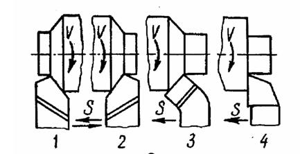
Fig.1. Turning patterns
1 - longitudinal turning with a straight through left cutter
2 - longitudinal turning with a straight through right cutter
3 - longitudinal turning with a bent right cutter
4 - longitudinal turning with a thrust right cutter
Finishing allowances vary within 1-2 mm or less per side. Turning is carried out with cutters with a rounded cutting edge and wide cutters.
For turning end surfaces scoring cutters are used (Fig. 2). When processing the end surfaces, the workpieces are fixed in the same way as when processing the outer cylindrical surfaces. When fixing in the chuck, the overhang of the workpiece should be minimal. To trim the end of the workpiece when fixing it with a clamping back center, a special cut off reference fixed center is used.
Fig.2. Trimming the ends with cutters:
a) straight through
b) bent through
c) through-thrust
d) undercut
Boring of pre-drilled holes or holes obtained during blanking operations is performed by roughing and finishing (with a loaded cutting edge) cutters. Boring cutters for through holes have a main angle of entry less than 90 o, for boring cutters for blind holes, the angle is equal to or slightly greater than 90 o (Fig. 3).
Fig.3. Boring a through hole (a) and a blind hole (b) with a boring
peeling cutter
Cutting parts of workpieces and turning annular grooves are produced by cutting cutters and slotted (grooving) cutters (Fig. 4).
Fig.4. Grooving with a grooving tool or parting with a parting tool
For processing shaped surfaces, round and prismatic shaped cutters or copiers are used.
Tapering
The processing of conical surfaces can be carried out by the following methods:
1. By offsetting the tailstock housing
2. Turning the carriage of the upper caliper
3. With the help of a copy ruler
4. Turning with a wide cutter
Turning conical surfaces by transverse displacement of the tailstock body (Fig. 5)
![]()
Fig.5. Turning of cones by transverse displacement of the body of the tailstock
1-drive cartridge; 2- front center; 3- collar;
4- rear center; 5- tailstock quill; 6 - blank; 7 - cutter
With this method, the axis of centers is shifted by shifting the rear center in the transverse direction. The generatrix of the machined conical surface of the workpiece, installed in the centers of the headstock and tailstock, will be parallel to the line of the centers of the machine.
The value of the transverse displacement of the tailstock body is determined by the formula:
where: d- diameter of the small base of the cone, mm; D is the diameter of the large base of the cone, mm; L– the length of the entire workpiece being processed, mm; l is the height of the conical surface, mm.
In this way, long outer conical surfaces with a slight taper with an angle of not more than .
The disadvantages of the method: impossibility of processing internal conical surfaces; the possibility of obtaining only gentle cones; increased and uneven wear of centers and center holes due to misalignment of centers.
Processing of conical surfaces by turning the carriage of the upper support (Fig. 6).
Fig.6. Turning cones by turning the carriage of the upper support.
1- three-jaw chuck; 2 - blank; 3 - handle for manual movement of the upper caliper; 4 - upper support with a tool holder; 5 - cutter
In this way, short conical surfaces are turned (and bored) with any cone angle. To do this, the carriage of the upper caliper is rotated through an angle equal to half the angle at the top of the cone being machined. Processing is carried out with manual feed of the upper caliper at an angle to the line of machine centers. The angle value is determined from the expression:
The disadvantages of the method: the use of manual feed, which reduces labor productivity and increases the roughness of the machined surface; the impossibility of turning conical surfaces, the length of the generatrices of which exceeds the stroke length of the upper support carriage (100-150 mm).
Turning a conical surface with a wide turning tool (Fig. 7).
Fig.7. Turning cones with a wide turning tool
1 - three-jaw chuck; 2 - blank; 3 - rear center; 4 - cutter
In this way, short conical surfaces are turned with a generatrix length of not more than 25-30 mm with turning cutters, in which the main angle in the plan is equal to half the angle at the top of the turned conical surface. The length of the main cutting blade of the cutter should be 1-3 mm longer than the length of the generatrix of the conical surface. Processing is carried out with a transverse or longitudinal feed of the cutter. The method is widely used for chamfering machined cylindrical surfaces.
The disadvantages of the method: inability to process long tapered surfaces, as with an increase in the length of the part, vibrations occur that increase the roughness of the treated surface; low quality of the processed surface.
4. 2. Main types of turning tools
Turning cutters are classified according to a number of criteria.
1. By the type of work performed or by technological feature: through (1), undercut (2), boring (3), cut-off (4), threaded (5), etc.
2. According to the shape of the incisor head: straight (1), bent (2), curved (3), drawn (4).
3. In feed direction: left(1), right(2).
Right a cutter is called, in which the main cutting edge is located on the side of the thumb of the right hand, placed with the palm on the cutter so that the fingers are directed towards the top of the cutter. When turning with such cutters, the chips are cut off from the workpiece when the caliper is moved from right to left.
Left a cutter is called, in which the main cutting edge is located on the side of the thumb of the left hand, placed with the palm on the cutter so that the fingers are directed towards the top of the cutter. When turning with such cutters, the chips are cut off from the workpiece when the caliper is moved from left to right.
4. According to the material of the cutting part: high speed steel, hard alloy.
5. According to the design of the cutting part: solid and composite (with a soldered plate or with a mechanical fastening of the cutting plate).
4.3. Elements and geometric parameters of a turning tool
Any cutting tool consists of two parts: I - cutting part; II - fastening part (Fig. 8).
Fig.8. Elements of a turning tool
On the cutting part, the following elements are distinguished:
1 - the front surface along which the chips come off
2-main back surface adjacent to the main blade
3-main cutting blade
4-top cutter
5-auxiliary back surface adjacent to the auxiliary blade
6-auxiliary cutting blade
4. 4. Geometry of cutters in static
4.4.1. Coordinate planes
To carry out the cutting process, the cutter is sharpened along the front and back surfaces. To read the angles of the cutter, coordinate planes are used (Fig. 9, 10).
Main plane(OP) is a plane parallel to the directions of the longitudinal ( S pr) and transverse ( S p) innings. For turning cutters, the main plane usually coincides with the lower bearing surface of the cutter shaft.
Fig.9. Coordinate planes
cutting plane(PR) passes through the main cutting blade of the cutter, tangent to the cutting surface of the workpiece.
Principal cutting plane (NN) passes through an arbitrary point of the main cutting blade perpendicular to the projection of the main cutting blade onto the main plane.
Auxiliary cutting plane passes through an arbitrary point of the auxiliary cutting blade perpendicular to the projection of the auxiliary cutting blade onto the main plane.
Fig.10. Geometrical parameters of the cutting part of the direct turning
through cutter
4.4.2. Turning tool angles
The main sharpening angles of the cutter are measured in the main cutting plane.
front angle call the angle between the front surface and the plane perpendicular to the cutting plane, drawn through the main cutting blade.
back angle called the angle between the main back surface of the cutter and the cutting plane.
The angle between the front and main rear surfaces is called taper angle incisor.
The angle between the rake face and the cutting plane is called cutting angle .
Plan angles are defined in the base plane.
Leading angle- the angle between the projection of the main cutting blade on the main plane and the feed direction.
Auxiliary lead angle- the angle between the projection of the auxiliary cutting blade on the main plane and the direction opposite to the feed direction.
Corner at the top of the cutter- the angle between the projections of the main and auxiliary cutting blades on the main plane.
Angle of inclination of the main cutting blade measured in a plane passing through the main cutting blade perpendicular to the main plane, between the main cutting blade and a line drawn through the tip of the cutter parallel to the main plane.
The angle can be positive (the cutter tip is the lowest point of the main cutting blade), negative (the cutter tip is the highest point of the main cutting blade), or zero.
Auxiliary cutter angles considered in the auxiliary cutting plane.
Auxiliary rear corner- the angle between the secondary rear surface and the plane passing through the secondary cutting edge perpendicular to the main plane.
Appointment of angles
Rear angle serves to reduce friction between the back surface of the cutter and the workpiece. With a decrease in friction, heat and tool wear decrease, but with a large back angle, the cutter will weaken and may break. As the clearance angle increases, the surface finish improves. The softer the metal, the larger the angle should be. Corner at the top of the cutter
The rake angle has a great influence on the vibration resistance of the cutter, which decreases sharply with a decrease in its value (from zero and below). Therefore, in order to avoid the appearance of vibrations, it is necessary to take a front angle of 15-25 °, and usually it is made equal to the angle of insertion of the plate. In order to ensure chip curling and favorable removal of it, it is recommended to make the front surface of the cutter either curved or with a hole. To harden the main cutting edge, it is advisable to provide a ribbon 0.2-0.3 mm wide with a negative rake angle of -3 - 5°. However, we should not forget that such a ribbon is permissible only if there are sufficiently severe working conditions for the cutter. 15 If stiffness conditions do not allow the use of a reinforcing tape with a negative angle, it is recommended to make it with a positive angle of 5° for hard and 10° for soft and viscous materials. The reinforcing band, with its small width, does not affect the value of cutting resistance, since the center of chip pressure extends beyond the band boundary into the area of the curved front surface provided with a large rake angle.
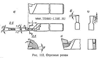
Figure 66 - Cut-off tool angles
In practice, there are cutting cutters, in which the front surface is formed in the form of a dihedral angle (Fig. 66, b). Its planes are inclined to the reference plane at an angle μ = 10÷15°. The line of intersection of these planes is parallel to the reference plane. This design contributes to better penetration of the cutter into the workpiece.
Rear corner
The rear angle of the main cutting edge is taken equal to 8º on the plate and 12° on the holder.
cutting edge
The main cutting edge of the cutter can be designed in several ways. For cutting off large workpieces, a cutter with two cutting edges can be recommended (Fig. 66, c)². They ensure the separation of the chips into two parts, which makes it easier to remove them from the cutting zone. This design is more suitable for high speed steel cutters, while it is less suitable for carbide cutters due to the difficulty of sharpening and the low strength of the cutting edge.
Noteworthy is the design of the main cutting edge at two angles φ (Fig. 66, d). This shape facilitates the cutting of the cutter into the workpiece and lengthens its edge. Plan angles φ are accepted within 60-80° (ς = 30 ÷10º).
In the event that the main cutting edge is made at an angle φ = 90°, it is recommended to chamfer f = 1 ÷ 1.5 mm on it at an angle of 45° on both sides or make small roundings (Fig. 66, e).
In practice, there are cases when, during cutting, it is undesirable to leave the cylindrical process at the core of the workpiece uncut (for example, when processing on automatic machines). To cut such a rod, the cutting edge is formed at an angle φ = 75 ÷ 80°.
Increased vibration resistance
Sometimes blanks are cut with a cutter, in which the main cutting edge has a concave shape, obtained by grinding a hole on the main back surface (Fig. 66, g). The purpose of this form is to increase the vibration resistance of the cutter and the possibility of increasing the feed rate.
Severe working conditions of cutting cutters force, as a rule, to use them in the form monolithic construction, whereas prefabricated structures are rarely found in practice.
- 4515 views


