Cutter turning through straight bent right and left VK8,T15K6
Among all types of metal cutting turning, perhaps the most common and frequently used. It is characterized by the fact that a certain layer of material is cut off from the surface of the workpiece using cutters, drills and other tools, as a result of which the part acquires the necessary geometric configuration.
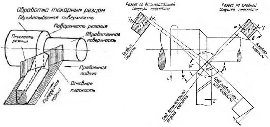
When in progress turning the cutting process is carried out, then the rotation of the part clamped in the chuck is called the main movement. In this case, the cutting tool moves relative to the surface of the part progressively (due to which a certain layer of material is removed), and this movement is called the feed movement. Thus, on turning equipment processing of cylindrical, shaped, threaded, conical and other surfaces is carried out by a combination of the main movement and the feed movement.
For implementation turning parts on modern equipment, various types of tools are used, one of which is through bent cutter.
By using through bent incisors operations such as turning the outer surfaces of parts using a longitudinal feed, as well as trimming the ends and chamfering, which is done using a transverse feed, are carried out.
All produced in Russian Federation through curved incisors, the working part of which is equipped with high-speed steel plates, must comply with the requirements GOST 18868-73.
Requirements for cutting toolsModern lathes this is technological equipment, which uses a variety of cutting tools. It should be borne in mind that it is the tool that operates in much harsher conditions than any part of the machine. For this reason, very serious requirements are imposed on the material from which the cutting tool for lathes is produced.
The main requirement for it is a high degree of hardness. The value of this indicator should be at least not lower than that of the workpiece: otherwise, it will not be able to cut, but will be crushed by itself.
Since the cutting tool experiences large friction forces during the processing of parts, it must be wear-resistant.
During cutting, a mass of thermal energy is released in the form of heat, and therefore the cutting tool, in order to maintain its working properties under conditions high temperatures must be heat resistant.
It goes without saying that high mechanical strength must also be attributed to the main qualities of a cutting tool. It is necessary in order to successfully perceive large cutting forces.
The material from which the turning cutting tool is made must work well both in compression and in bending. It should also be well calcined and polished.
According to general rule, through curved incisors are installed in lathes in such a way that their cutting part is located exactly in the center of the workpiece. However, deviations from the center line are also allowed, which should be no more than one hundredth of the diameter of the workpiece.
Sharpening of a turning tool can be carried out during the manufacture of this tool, and always when working with it, that is, as it wears out. For this, specialized grinding equipment is used, with mandatory cooling. The level of sharpening of turning tools seriously affects the quality of the machined surface.
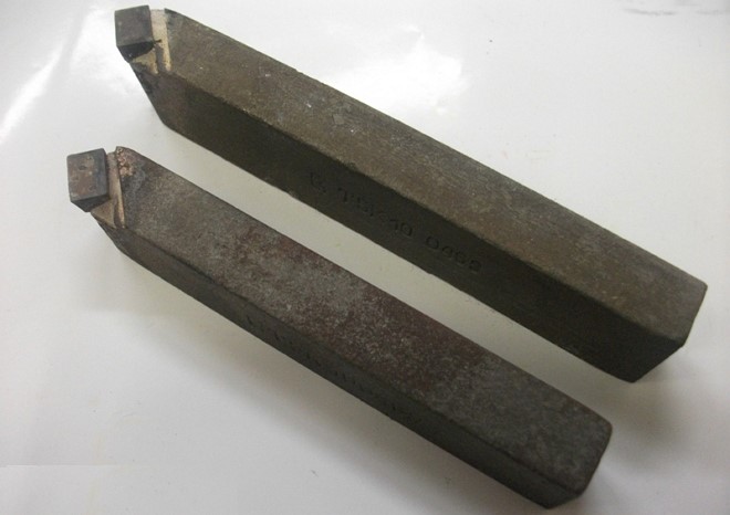
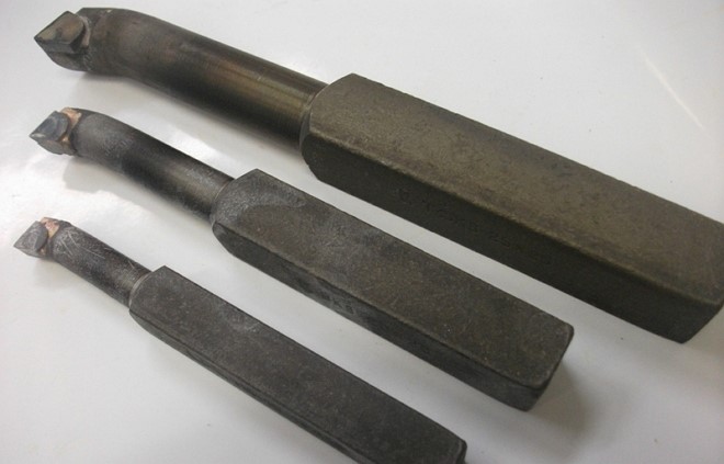
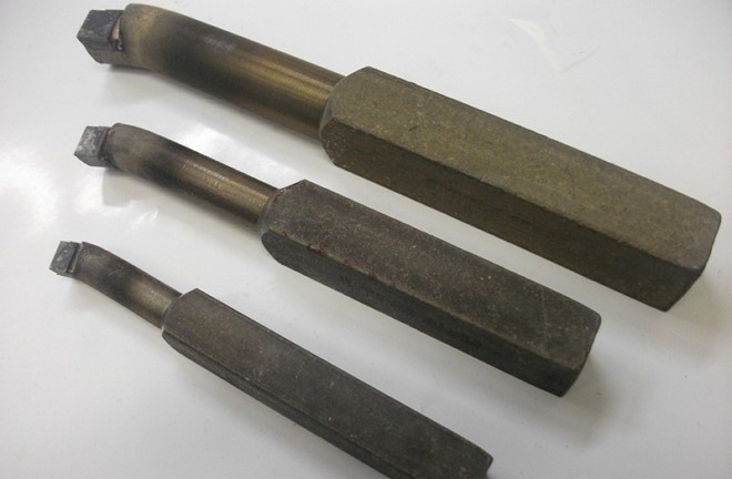
The bent pass cutter is used for turning the outer surfaces of rotation parts, which include conical surfaces long lengths, cylindrical rollers and other things. Unlike straight cutters, bent through cutters are more widespread, as they have universal capabilities in work. They have higher rigidity and due to their shape, they can process parts even in hard-to-reach places. They are used to create parts, draft and finishing workpieces in mechanical engineering and machine tool building, in almost every professional turning workshop, a bent through cutter is an indispensable tool for processing.
photo: turning cutters through bent
The work of this tool is carried out both with longitudinal and transverse feed. They can perform turning on top of the workpiece itself, chamfering and trimming the ends, that is, all the basic operations that may be useful in this case. They belong to wide-profile tools and have several different variations in size and other parameters. They perform well in working with hard parts. The bent through cutter is manufactured in accordance with GOST 18868-73.
Types of turning through bent cutters
Tools of this type can be divided into finishing and draft types. Finishing ones have a significantly larger radius of curvature. This allows you to get a more accurately machined surface. They are used at the final stage of production and for the creation of relatively small parts. If you need to achieve special smoothness and cleanliness, then, as a rule, spatula cutters are used, which help to achieve better results.
Roughing is used for rough processing. Their radius of curvature is lower, but the fortress is noticeably higher. They are great for when you need to shoot. a large number of metal from the workpiece. Their working resource is much higher, therefore, from an economic point of view, processing with two types of cutters is much more profitable. They have less accuracy, but they will make the first stage of removal faster.
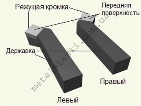
In addition, one can also distinguish such types as a right and left bent incisor through passage. Here they differ in the location of the cutting edge, as in many other varieties of these tools.
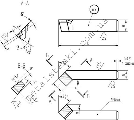
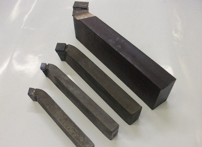
The main dimensions of the through curved cutters
| Height, mm | Width, mm | Length, mm |
|---|---|---|
| 16 | 10 | 110 |
| 20 | 12 | 120 |
| 25 | 16 | 140 |
| 25 | 20 | 170 |
| 32 | 25 | 170 |
| 40 | 25 | 200 |
| 40 | 32 | 240 |
| 40 | 40 | 240 |
| 50 | 40 | 240 |
| 50 | 50 | 240 |

The bent through cutter is made mainly of carbide materials, because the workpieces mainly consist of hard materials, but tools made of high speed steel can also be used.
The geometry of the through curved cutter
The main working part of the cutter is its head, which is located on the rod. It is inserted into the tool holder for subsequent work. On the front surface of the head there is a surface that provides chip flow. There are also two trailing edges, auxiliary and main. They are called those surfaces that face the part being processed.
The main cutting work is carried out by the main cutting edge. This part is formed at the intersection of the main back and front surfaces of the tool. The design also provides for an auxiliary cutting edge formed at the intersection of the auxiliary front and rear surfaces. The intersection of the secondary and main cutting edges forms the tip of the cutter. Each model creates its own unique angle, which makes the product more suitable for certain purposes. For example, machining a step-type part requires a cutter with an angle of 90 degrees.
Choice of through curved cutter
Curved turning cutters are available in several versions, which differ in size, cutter material and other parameters. When choosing, you should pay attention to what blanks you have to deal with. If a wide range of parts is used in production, then you should have not one curved pass-through cutter, but a whole set for various cases.
The size of the product is selected according to the dimensions of the workpiece. The most common are medium options that do not require replacement for most work with various types of products. “Advice of professionals! Frequent change of cutters results in a lot of wasted time and equipment downtime, so the best options should be determined in advance. ”
With regard to the material, there is a simple trend here, when soft and non-hardened grades of metal are processed by straight-through cutters, bent left and right, which are made of high-speed steel. It is cheaper, but less practical when it comes to hard materials. In this case, you should use a bent through-thread cutter with a cutter made of carbide materials. They perfectly withstand vibrations and temperatures that rise during operation, therefore, their service life is much longer.
Cutting conditions
The bent turning cutter is used in fairly simple modes of operation. They carry out longitudinal and transverse movements, depending on the processing profile. You can choose and order self-tapping screws for a metal profile at the best price in Ukraine on Stream. It is recommended that you first make a roughing with one tool designed specifically for this purpose, and then make a finishing pass on an almost finished surface. If in roughing a thickness of up to several millimeters is gradually removed, then in finishing this figure goes to tenths of a millimeter in several passes.
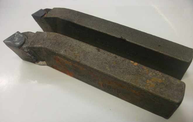
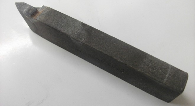
Marking
On the example of such a tool as a bent through cutter T15K6, we can consider an example of marking. The working surface here is made of hard-alloy materials that belong to the titanium-tungsten group. The content of cobalt (K6) is 6%, and titanium carbide (T15) is 15%.
Manufacturers
- CHIZ (Chernihiv, Ukraine);
- Ukrmetiz (Ukraine);
- Intertool (China);
- Melitopol Instrument LLC;
- Seco (Sweden).
Through curved cutters: Video
Professionals who often use incisors for lathe when performing metal work, as well as those who sell these products or supply engineering enterprises are well aware of the types of these instruments. For those who rarely encounter turning tools in their practice, it is quite difficult to understand their types, which are presented on the modern market in a wide variety.
Types of turning tools for metal processing
Turning cutter design
In the design of any cutter used for, two main elements can be distinguished:
- holder, with which the tool is fixed on the machine;
- working head through which metal processing is performed.
The working head of the tool is formed by several planes, as well as cutting edges, the sharpening angle of which depends on the characteristics of the workpiece material and the type of processing. The cutter holder can be made in two versions of its cross section: square and rectangle.

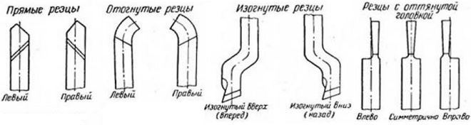
According to their design, cutters for turning are divided into the following types:
- straight - tools in which the holder together with their working head are located on one axis, or on two, but parallel to each other;
- curved cutters - if you look at such a tool from the side, you can clearly see that its holder is curved;
- bent - the bend of the working head of such tools in relation to the axis of the holder is noticeable if you look at them from above;
- drawn - for such cutters, the width of the working head is less than the width of the holder. The axis of the working head of such a cutter may coincide with the axis of the holder or be offset relative to it.
Classification of cutters for turning
The classification of turning tools is regulated by the requirements of the relevant GOST. According to the provisions of this document, incisors are assigned to one of the following categories:
- one piece tool made entirely of . There are also incisors that are made entirely of, but they are used extremely rarely;
- cutters, on the working part of which a plate made of hard alloy is soldered. Tools of this type are most widely used;
- cutters with removable carbide inserts that are attached to their working head with special screws or clamps. Cutters of this type are used much less frequently compared to tools of other categories.
(click to enlarge)
The incisors also differ in the direction in which the feed movement takes place. So, there are:
- turning tools of the left type - in the process of processing they are fed from left to right. If you put your left hand on top of such a cutter, then its cutting edge will be located on the side of the bent thumb;
- right incisors - the type of tool that has received the greatest distribution, the feed of which is carried out from right to left. To identify such a cutter, you need to put your right hand on it - its cutting edge will be located, respectively, on the side of the bent thumb.

Depending on what work is performed on turning equipment, cutters are divided into the following types:
- to perform finishing work on metal;
- for rough work, which is also called peeling;
- for semi-finishing work;
- to perform fine technological operations.
In the article we will consider the entire spectrum and determine the purpose and features of each of them. An important clarification: no matter what type the cutters are, certain grades of hard alloys are used as the material of their cutting inserts: VK8, T5K10, T15K6, much less often T30K4, etc.
Use a tool with a straight working part to solve the same tasks as the bent type cutters, but it is less convenient for chamfering. Basically, such a tool for (by the way, not widely used) processes the outer surfaces of cylindrical blanks.
The holders of such cutters for a lathe are made in two main sizes:
- rectangular shape - 25x16 mm;
- square shape - 25x25 mm (products with such holders are used to perform special work).
Such types of cutters, the working part of which can be bent to the right or left side, are used for processing the end part of the workpiece on a lathe. With their help, chamfers are also removed.
Tool holders of this type can be made in various sizes(in mm):
- 16x10 (for training machines);
- 20x12 (this size is considered non-standard);
- 25x16 (the most common size);
- 32x20;
- 40x25 (products with a holder of this size are made mainly to order, they are almost impossible to find in the free market).
All requirements for metal cutters for this purpose are specified in GOST 18877-73.
Such tools for a metal lathe can be made with a straight or bent working part, but they do not focus on this design feature, but simply call them through-thrust.
checkpoint stop cutter, with the help of which the surface of cylindrical metal blanks is machined on a lathe, is the most popular type of cutting tool. The design features of such a cutter, which processes the workpiece along the axis of its rotation, make it possible to remove a significant amount of excess metal from its surface even in one pass.
Holders of products of this type can also be made in various sizes (in mm):
- 16x10;
- 20x12;
- 25x16;
- 32x20;
- 40x25.
This tool for a metal lathe can also be made with a right or left bend of the working part.
Outwardly, such a scoring cutter is very similar to a through cutter, but it has a different shape of the cutting plate - triangular. With the help of such tools, workpieces are processed in a direction perpendicular to their axis of rotation. In addition to bent, there are also persistent types of such turning tools, but their scope is very limited.
This type of cutter can be produced with the following holder sizes (in mm):
- 16x10;
- 25x16;
- 32x20.
The cut-off tool is considered the most common type of tool for a metal lathe. In full accordance with its name, such a cutter is used for cutting workpieces at a right angle. It also cuts grooves of various depths on the surface of a metal part. It is quite simple to determine that it is a cutting tool for a lathe that is in front of you. His feature is a thin leg, on which a hard alloy plate is soldered.

Depending on the design, right- and left-handed types of cut-off cutters for a metal lathe are distinguished. It is very easy to tell them apart. To do this, you need to turn the cutter with the cutting plate down and see which side its leg is located on. If on the right, then it is right-handed, and if on the left, then, respectively, left-handed.
Such tools for a lathe for metal also differ in the size of the holder (in mm):
- 16x10 (for small training machines);
- 20x12;
- 20x16 (the most common size);
- 40x25 (such massive turning tools are hard to find on the free market, they are mostly made to order).
Thread cutters for external threads
The purpose of such cutters for a metal lathe is to cut threads on the outer surface of the workpiece. These serial tools cut metric threads, but you can change their sharpening and cut other types of threads with them.
The cutting insert mounted on such turning tools has a spear-shaped shape; it is made from the alloys that were mentioned above.
Such cutters are made in the following sizes (in mm):
- 16x10;
- 25x16;
- 32x20 (used very rarely).
Such cutters for a lathe can only cut threads in a large diameter hole, which is explained by their design features. Outwardly, they look like boring cutters for processing blind holes, but do not confuse them, since they are fundamentally different from each other.

Such cutters for metal are produced in the following sizes (in mm):
- 16x16x150;
- 20x20x200;
- 25x25x300.
The holder of these tools for a metal lathe has a square section, the dimensions of the sides of which can be determined by the first two digits in the designation. The third number is the length of the holder. This parameter determines the depth to which a thread can be cut in the inner hole of a metal workpiece.
Such cutters can only be used on those lathes that are equipped with a device called a guitar.
Boring cutters for blind holes
Boring cutters, the cutting plate of which has a triangular shape (as with scoring cutters), perform the processing of blind holes. The working part of tools of this type is made with a bend.
The holders of such cutters can have the following dimensions (in mm):
- 16x16x170;
- 20x20x200;
- 25x25x300.
The maximum hole diameter that can be machined with this turning tool, depends on the size of its holder.
Boring cutters for through holes
With such cutters, the working part of which is made with a bend, through holes are processed, previously obtained by drilling. The depth of the hole that can be machined with a tool of this type depends on the length of its holder. The layer of metal that is removed in this case is approximately equal to the value of the bend of its working part.
On the modern market there are boring cutters of the following sizes, the requirements for which are specified in GOST 18882-73 (in mm):
- 16x16x170;
- 20x20x200;
- 25x25x300.
Prefabricated cutters for lathes
Considering the main types of turning tools, it is impossible not to mention tools with a prefabricated structure, which are universal, as they can be equipped with cutting inserts for various purposes. For example, fixing cutting inserts on one holder various types, you can get cutters for different angles.

As a rule, such cutters are used on CNC machines or on special machines and are used for contour turning, boring blind and through holes, and other specialized work.
Thrust cutters are the most common tool in turning. In this article, we will look at how to make such a cutter with our own hands, what kind of through cutters are, their installation angles and cutting edge angles, and other nuances.
This article will be a continuation of a series of articles on the site about lathes, tools and fixtures for turning in a garage workshop. I already wrote about fixtures for lathes and those who wish can read about them and. Well, about competent sharpening and fine-tuning of turning tools with my own hands, I advise you to read and watch the video here in
And in this article we will take a closer look at the main tool for turning - a through cutter.
To begin with, let's consider what kind of through cutters are, what they are made of, their sharpening angles, methods of fastening the carbide plates of these cutters and other nuances. And at the end, it will be told and shown how to make a bent through cutter with a replaceable carbide plate at home with your own hands.
The pass-through cutter is designed for longitudinal turning of outer cylindrical surfaces, and scoring cutters are used for turning ledges and end surfaces. However, some types of through cutters (such as I did in the video below the article and in Figure 1 below) and scoring cutters are used for both longitudinal and transverse turning of surfaces.
Through cutters are fine and rough. Roughing cutters are designed for rough turning of workpieces, the so-called peeling (and therefore some call them peeling). And finishing cutters are intended for final surface treatment and obtaining a higher class of workpiece surface finish. Below we will consider in detail the types of through cutters.
Turning bent through cutters .
Such cutters are most common in turning due to their convenience and wide possibilities, and it was how I made such a cutter that I filmed a video that can be viewed under this article. Due to the bent head, such cutters allow you to process the surface of a part that is located very close to the cams of the lathe chuck.
I - longitudinal turning, II - transverse turning
And such a cutter is used for both longitudinal (see Figure 1.I) and transverse turning (Figure 1.II). Such cutters are made right and left, depending on which way the head is bent.
Straight cutters.
I - right through cutter, II - left through cutter
These cutters are designed for longitudinal turning of parts. As well as bent cutters, they can be either right (see Figure 2.I), which are used in the normal direction of movement of the machine support, and left (Figure 2.II), which are used when turning in the direction from the headstock to the back.
Straight through cutters are the easiest to manufacture due to the simple (not bent) shape of the holder.
Persistent through cutters.
I - cutting end surfaces (ledges), II - end turning.
These cutters serve for longitudinal turning of parts (see Figure 3.I) and simultaneous trimming of the end surfaces of the ledges (at the end of the passage). If you turn the tool holder with such a cutter at a certain angle (see Figure 3.II), you can use such a cutter for face turning of the end of the part.
Thrust cutters are most widely used in the processing of non-rigid parts, as well as stepped workpieces.
Finishing cutters .
I - for turning open places, II - for turning hard-to-reach places.
Such cutters are used mainly for turning with low feed and they differ from conventional through cutters in a large radius of curvature (r = 2-5 mm).
For turning open areas on parts, use straight cutters that work in both directions (see Figure 4.I). And for turning hard-to-reach places, bent cutters are used (see Figure 4.II), both right and left.
Finishing wide cutters .
These cutters are designed for fine turning of parts, and with high feeds. But at the same time, these cutters usually remove a very small layer of metal from the workpiece.
b is the width of the cutting edge, s is the feed.
At high feeds (s
Below we will consider various options for through cutters, which differ from each other depending on the attachment of the cutting plates.
Turning cutters with mechanical fastening of cutting plates.
Fastening of plates in a special nest of a cut spring holder.
The design of such cutters (which were developed back in the last century at the Institute of Technology in the GDR) provides for the fastening of symmetrical carbide inserts in cut holders using one or two screws (with an internal hexagon). Such through cutters are shown in the figure below.
This plate is fixed by wedging it between the pin 3 and the rear supporting wall of the holder using a special wedge 5 and screw 4. In this case, the plate is firmly and tightly pressed against the supporting surface of the cutter body (holder).
As shown in the figure, the plate, when manufactured at the factory, is supplied with a fillet for curling chips and another hardening chamfer on the front surface (chamfer width 0.2 - 0.3 mm). Moreover, the rake angle on the fillet is positive and the required value of the back angles is provided by installing the plate at the desired angle on the holder body (the angle is approximately 15 - 18 ° relative to the axis of the holder).
The described design for attaching a changeable plate is a little difficult to do on your own at home, and it will not work for too small cutters of small lathes (for example, school "tevashkas"), since all the details will have to be made very small. Therefore, for smaller incisors, you can attach an interchangeable plate in a simpler way, as I did in the video under this article.
And if you make a step on the holder accurately enough, and accurately drill a hole for the clamping screw, that is, ensure that when the screw is tightened, the plate is tightly attracted by its back face to the step (shoulder on the holder), then such a fastening, despite its simplicity, is quite reliable.
In addition, the step is made in such a way that, under load, the rear edge of the plate is wedged in the step, because the step and the support platform for the plate are made with an angle (about 10 - 15 ° with respect to the axis of the holder). The holder is preferably made of carbon steel 40X, 40X13, or steel 45, 50.
Making curved incisors using a stamp. 1 - matrix, 2 - pressing punch.
Moreover, the holder of the bent cutter was made (and shown by me in the video below) not by bending, as they do at the factory with the help of special dies and as shown in the figure on the left, but in a simpler way, simply by cutting and turning from a piece of steel.
Polyhedral plates are produced in three, four, five, and hexagonal shapes. Well, the dimensions of through cutters with polyhedral plates practically do not differ from the sizes of cutters with soldered carbide plates of the same height.
Triangular inserts have angles equal to 80º, at working tops, and they are used for through thrust cutters with a leading angle φ=90º (see figure under letter a below).
Often in production, in order to process various stepped rollers and a variety of non-rigid parts, a through cutter is used. When working with this tool, roughing passes are obtained with a smaller radius of curvature than finishing passes. If necessary, to obtain perfectly smooth surfaces, use a blade cutter through.
The through cutter is used for external longitudinal finishing and finishing turning of various parts. At the same time, higher cutting speeds are used for roughing, and chips are removed larger than with fine turning.
The through cutter can be bent, persistent and straight. And in the feed direction, there are right and left tools. In this case, the left ones are used for processing external surfaces in the direction from left to right, the right ones - from right to left.
The straight through cutter has the main angles in the plan equal to φ = 75, 60 and 450, the bent cutter φ = 400-450 and the thrust tool φ = 900. the resistance of the entire cutter as a whole, while the smaller the angle, the higher the allowable speed and resistance of the cutter. However, often at the minimum values of this characteristic, vibrations may occur due to insufficient rigidity of the machine structure, fixing parts or the tool itself. So, with sufficient rigidity, a bent pass-through cutter is used, which is the most widespread due to the fact that it allows you to do not only longitudinal, but even transverse turning. If the rigidity is not sufficient, stop cutters are used, which allow processing parts with small ledges and are widely used for processing non-rigid parts.
Another, no less important parameter is the auxiliary angle in the plan. It affects the cutting speed, the roughness of the surface being turned and reduces the participation of the auxiliary cutting edge in the whole process. When roughing, this value for the tool is selected 10-150.
The next important characteristic of such a tool as a through cutter is the radius of curvature. It affects tool life and cutting edge strength. An increase in this parameter reduces the roughness of the surface to be machined, but at the same time causes an increase in the load on the feed cutter itself, which contributes to vibration. So the radius for tools with carbide inserts of 0.5 mm is considered optimal with a holder cross section of 10 mmx16 mm and 12 mmx20 mm, 1 mm for sections of 16 mmx25 mm and 20 mmx32 mm, 1.5 mm for cutters with a cross section of 25 mmx40 mm and 30 mmx45 mm.
The shape of the front surface of the cutter depends on the material being processed, the required nature of the processing, the option of feeding the product and a number of other conditions. So, for example, a flat shape of sharpening and a positive angle is used on all types of high-speed and carbide cutters, it is recommended for processing cast iron. At the same time, the feed cutter made of high-speed steel has a feed rate of less than 0.2 mm/rev when turning steel.
A flat shape with a negative rake angle is used for cutters with hard alloy blades when processing steel over 80 kgf/mm2, in the presence of a rigid technological system.
Very often, the through cutter is additionally strengthened by chamfering 0.2-1.2 mm with a negative angle of up to -50 along the cutting edge. A flat shape with a chamfer is used for a tool made of high-speed steel, when used for turning steel with a feed rate of more than 0.2 mm / rev, as well as for carbide cutters for processing steel with σv less than or equal to 80 kgf / mm2, as well as with σin more than and equal to 80 kgf/mm2 in the presence of a non-rigid system. It is used for processing steel and steel castings, as well as for malleable cast irons.
However, when working with such a tool, a large amount of dangerous, slightly curled and inconvenient for transporting chips is formed. At the same time, there is a high probability that it will wrap around the part and become dangerous for the worker. To avoid this, the chips are curled, making the front part of the cutter with a fillet with a radius from 3 mm to 18 mm, and for machining parts with lower strength, a smaller radius value is chosen. Thus, a cutter of the following form is obtained.
The pass cutter, having a radius shape with a chamfer, is designed for all types of tools made of high-speed steel, except for shaped cutting edges with a complex profile, as well as for tools with carbide inserts when fed at a speed of more than 0.3 mm / rev for the necessary processing of steel with σin more than and equal to 80 kgf/mm2.
Regardless of the cutter being used, in order for it not to fail longer and work with the greatest efficiency, a huge number of various additional nozzles and various auxiliary devices are used. They are designed to protect the tool, and also simplify the entire technological process, which is especially important when processing parts that have a complex structure.
Tap
 A tap is a cutting tool for cutting threads in a pre-drilled hole. The tap is a cylindrical roller with cutting edges at one end. The other end of the tap (shank) is designed to be fixed in the chuck or to hold it in the collar during operation.
Main types of taps:
Manual - designed for manual threading in a set consisting of two or three pieces;
Nut - for cutting in one pass a full thread in through holes;
Machine - for threading, mainly in blind holes on drilling machines, automatic machines and special modular machines (Mainly pieced ones are produced, but they also come in sets of 2 or 3 pieces);
Machine tools - for obtaining threads in through holes on nut-tapping machines; grooveless (forming machines) - for cutting threads in through holes in one pass;
Automatic - for cutting threads in nuts on nut-tapping machines;
ram and uterine - for threading and calibrating and removing burrs in the threaded holes of round dies.
Thread types: M, G, Rc, K, Tr, UNF, UNJF, BSW/BSF, BSP, NPT, NPTF, BSPTr, NGT.
The material for the manufacture of taps is alloyed tool and high-speed cutting steel.


