Features of tenoning machines for wood and their types, comparison. Tenoning machines: classification, purpose, general principles of operation
13 May 2013
In the previous issue of the magazine, we examined the most massive group of representatives of a large family of tenoning machines, namely, one-sided tenoning machines. Let's continue our review.
The family of tenoning machines includes the following main types:
- bilateral;
- for milling spikes of furniture parts (rounded and at an angle to the end of the part);
- for milling box spikes;
- for milling (cutting) toothed spikes.
Types of tenoning machines
Bilateral for joiner's products.
Such tenoning machines appeared after one-sided ones due to the need to increase labor productivity at medium and large woodworking enterprises, as well as to ensure higher accuracy of the distance between the shoulders of the tenons during their simultaneous milling, in contrast to the manufacture of the same parts on a single-sided machine.
Conveyor-fed double-sided tenoners for frame dowels consist of two units, each with six to four spindles. According to the classical scheme*, the spindles with the circular saw blade are placed first in the feed direction, then the horizontal tenon cutters form the cheeks of the tenon, then two profile cutters located on two vertical spindles perform the undercutting of the hangers, and the last are the lug discs on the vertical spindles that carry out milling eyes.
The presence in each block of six spindles with adjustable vertical and horizontal movement, as well as an inclination at an angle, ensure the versatility of the machine.
The feed is carried out by conveyor chains with stops, across which the workpieces are laid. A double-sided tenoning machine is serviced by a machine operator who controls the machine and loads it, and by an auxiliary worker who accepts workpieces from the opposite side of the machine.
In addition to cutting spikes on workpieces, the machine can cut panels with selection on the edges of tongues, ridges and other profiles.
The performance of a double-sided machine is almost 3-5 times higher than that of a single-sided machine.
We draw the attention of readers to the fact that during the operation of tenoning machines, the most common defect when cutting tenons is chipping of the tenon corners from the side of the trailing edge. When working on single-sided machines, to prevent chipping, a retaining bar of a sufficiently large initial length made of hardwood is used, mounted on a carriage and easily adjustable to compensate for wear during repeated milling of spikes.
On double-sided machines, it is impossible to use long (1000-1500 mm) retaining bars on the stops of the supply chains, since the length of the retaining bars is limited by the minimum possible distance between the shoulders of the spikes for specific machine models (for example, for model ШД10-8 it is 200 mm). Thus, this length, as a rule, cannot exceed about 100 mm, and therefore the service life of the retaining bars is very limited, which will require their periodic replacement.
To reduce labor costs with a fairly frequent replacement, as well as the cost of manufacturing retaining bars, machine-tool factories have proposed many different options for solving this problem, and this work continues to this day. Therefore, when buying a double-sided machine, you should pay close attention to these seemingly simple details, given the fact whether you will make them yourself or purchase them as spare parts.
Bilateral for furniture products.
Machines of the ШД10-8 type (see Table 1) are intended primarily for milling spikes and lugs on straight parts in the production of joinery and building products (windows, doors) and frames, for example, in the production of furniture.
However, in the production of classic-type furniture, which uses precious wood, the three-dimensional geometry of the parts, as a rule, is not rectilinear, but pronounced curvilinear. Therefore, the spikes of such parts have a rounded shape and are usually located in different planes.
For milling such spikes, a number of companies produce semi-automatic double-sided machines, in which the installation and regulation of all processing sizes can be carried out either manually using an indicator or using CNC.
In particular, Global EDGE supplies the Russian market with a tenoning machine model TSD/CSF2 (Fig. 1) for studding curved parts (Fig. 2).
A brief technical description of this machine is given in table 2.

For the production of box spikes.
Box spikes are straight - rectangular and oblique, as well as in the form of a dovetail: acute-angled and rounded - the latter are designed for open, semi-closed and closed joints.
The maximum strength of the box connection is provided by dovetail spikes of an open type and somewhat less by a semi-closed type. The lowest strength is given by connections to a rectangular box spike, since in this case it (strength) depends only on the quality of the adhesive seam, while the “dovetail” provides strength, firstly, due to mechanical connection, and secondly - by adhesive seam.
At present, unfortunately, machines for milling dovetail studs have practically disappeared from the scene, but machines of the ShPK40 type are still used for processing straight studs. This machine uses the principle of processing a set of cutters mounted on a horizontal knife shaft, a pack of boards, which is placed on a horizontal table that moves vertically up and down with the help of a hydraulic drive.
Main specifications machine ShPK40 are shown in table 3.
Manufacture of spikes for gear connections. In these machines, as a rule, two concepts are used - milling and tenoning and sawing and tenoning. In milling and tenoning machines, a toothed cutter is located on a vertical spindle, and the part is fed horizontally. IN Lately sawing and tenoning machines of the ShS-3 type (Fig. 3), which are used in the production of glued wooden structures and, in particular, glued beams for housing construction.
The main technical data of the machine model ШС-3 are given in table 4.

Setting up tenoning machines
This article proposes verification of accuracy standards for the two most common tenoning machines.
The first of them is a double-sided frame, which must meet the following accuracy standards (see Fig. 4) after installation or repair.
- Guide beds for the movable column must be straight in the vertical plane. It is checked by a level laid along a special test tile (bridge) or a ruler. The tolerance is 0.1 mm over a length of 1000 mm (Fig. 4a).
- The guide beds must be straight in the horizontal plane. Checked with a ruler and feeler gauge. The tolerance is 0.05 mm over a length of 1000 mm (Fig. 4b).
- The guide beds should not be twisted. It is checked by the level placed on a special tile (bridge). The tolerance is 0.1 mm over a length of 1000 mm (Fig. 4c).
- Both guide beds must be parallel to each other. It is checked with a caliper or a template and a feeler gauge. Tolerance - 0.2 mm (Fig. 4d).
- Conveyor chain guides must be straight. Checked with a ruler and feeler gauge. The tolerance is 0.1 mm over a length of 1000 mm (Fig. 4e).
- Both chain guides must be parallel to each other. It is checked with a shtihmas or measuring bars and a feeler gauge. The tolerance is 0.03 mm over the entire length (Fig. 4e).
- Both chain guides must lie in the same horizontal plane. Checked with a level and a ruler. The tolerance in the longitudinal direction is 0.2 mm over a length of 1000 mm and in the transverse direction is 0.3 mm over a length of 1000 mm (Fig. 4g).
- Spindles must not have radial runout. Checked with an indicator. Tolerance - 0.05 mm (Fig. 4h).
- The support flanges of the saw spindles and the eye disc must be free of axial runout. Tolerance - 0.05 mm on a diameter of 1000 mm (Fig. 4i).
- The axes of the horizontal spindles must be perpendicular to the feed direction. It is checked by an indicator mounted on the spindle when it is turned on the mandrel by 150-180 degrees. Tolerance - 0.05 mm for a length of 100 mm (Fig. 4k).
- The axes of the vertical spindles must be perpendicular to the feed direction. It is checked by an indicator on the working surface of the chain (or guide bars). Tolerance - 0.05 mm for a length of 100 mm (Fig. 4k).
- The axes of the vertical spindles must be perpendicular to the axes of the horizontal spindles. It is checked by a ruler placed on the working chains (or guide bars), by an indicator mounted on a vertical spindle, and by a stroke placed between the ruler and the horizontal spindle. Tolerance - 0.05 mm on a length of 100 mm (Fig. 4l).
- The direction of vertical movement of the calipers must be perpendicular to the horizontal plane passing through the bearing surfaces of the chains (or guide bars). It is checked with an indicator and a square mounted on a ruler placed on a chain (or guide bars). Tolerance - 0.1 mm over a length of 100 mm (Fig. 4n).
- The direction of horizontal movement of the calipers must be horizontal to the plane passing through the surfaces of the chain (or guide bars). Tolerance - 0.05 mm on a length of 100 mm (Fig. 4m).
- The axis of rotation of each spindle must be parallel to the direction of movement of the caliper. Checked with an indicator. Tolerance - 0.05 mm for a length of 100 mm (Fig. 4p).
- The working surfaces of the chains must be parallel to their guides. It is checked with an indicator and a ruler. Tolerance - 0.1 mm (Fig. 4p).
- The working surfaces of the stops of both chains must lie in vertical planes parallel to each other when the chains are moved. It is checked with an indicator and a ruler. Tolerance - 0.3 mm for a length of 1000 mm (Fig. 4c).
After alignment (Fig. 4t), the machine should produce spikes uniform in width (tolerance - 0.1 mm for a length of 100 mm) and thickness (tolerance - 0.1 mm for a length of 100 mm), parallel to the base surface of the bar (section 60x100 mm).

The second is the machine model ShPK40 for the manufacture of straight box and toothed (wedge) spikes, which, like the first, must satisfy the following checks for normal operation (see Fig. 5).
- The working surface of the table must be flat (only concavity is allowed). Checked with a ruler and feeler gauge. Tolerance - 0.1 mm over a length of 1000 mm (Fig. 5a).
- The working surface of the table must be horizontal in all positions in height. Level checked. The tolerance is 0.2 mm over a length of 1000 mm (Fig. 5b).
- The working surfaces of the square and stop must be flat. Checked with a ruler and feeler gauge. The tolerance is 0.04 mm over a length of 200 mm (Fig. 5c).
- The working surfaces of the square and the stop must be perpendicular to the working surface of the table. It is checked with a square and a probe. The tolerance is 0.1 mm over a length of 100 mm (Fig. 5d).
- The working surface of the square must be perpendicular to the axis of the spindle. It is checked with a square and a probe. Tolerance - 0.15 mm over a length of 200 mm (Fig. 5e).
- The working surface of the stop must be parallel to the axis of the spindle. It is checked with a square and a probe. Tolerance - 0.1 mm on a length of 250 mm (Fig. 5e).
- The spindle axis must be parallel to the working surface of the table. Checked with an indicator. Tolerance - 0.1 mm on a length of 400 mm (Fig. 5g).
- The spindle must not have radial runout. Checked with an indicator. Tolerance - 0.4 mm (Fig. 5h).
- The spindle must not have axial displacement. Checked with an indicator. Tolerance - 0.05 mm (Fig. 5i).
After alignment, the machine must ensure that the lugs and spikes are uniform in width. It is checked on a workpiece with a section of 40x400 mm when milling lugs 8 mm wide to a depth of 50 mm. Tolerance for lug width from 0 to +0.25 mm and stud width from 0 to -0.1 mm (Fig. 5k).

Machines of the tenon-cutting group allow, after processing the tenons, to assemble both simple frame products (in the production of windows and doors) and more complex ones - in the production of furniture.
But in the production of complex products, such as panel doors, cabinet furniture, etc., drilling and welding machines are needed, information about which will be given in the next article.
Vladilen Vinogradsky, Petr Landa
Magazine "Equipment: market, offer, prices", No. 07 July 2004


Price: 620 000 rubles
Manufacturer
Russia
Request
Description:
The machine is designed for forming (cutting) a toothed spike at the end of the workpiece (wooden beam) for further splicing along the length.
PACKAGE HEIGHT INCREASED TO 160 mm
MECHANICAL DRIVE OF THE CARRIAGE Main features:
· The mechanical feed of the carriage keeps a constant speed, which improves the quality of the tenon.
· The accelerated return motion of the carriage increases productivity of the machine.
· Width of a package of preparations - 500 mm.
· Rigidly fixed spindle and turntable provide quality tenon.
· Pneumopusher prevents repeated passage of the package of blanks on the cutter (tool wear decreases, tenon quality increases.
· Blow gun as standard.
· Drive belts Spindle Gates (USA)
· Protection against incorrect switching on (rephasing) and overvoltage.
· Milling cutter and scoring saw included.
· Spindle motor power of 7.5 kW allows you to cut a tenon on hard rocks with high quality.
Main technical characteristics:
Model name ShS-LOZA-03 Workpiece length, mm Workpiece width, mm Blank package width, mm Cutting saw diameter, mm Landing diameter of a cut-off saw, mm Saw speed, rpm Cut-off saw motor power, kW Cutter diameter, mm Landing diameter of the cutter, mm Cutter rotation frequency, rpm Milling motor power, kW Carriage feed speed, m/min Weight, kg
A feature of the machine is the work with a rotary table with a simultaneous shift of half a step. The top and side preload of the workpiece, as well as the movement of the carriage, is carried out by CAMOZZI pneumatics (Italy). Mechanical drive of the tenoning carriage (motor-reducer SITI, Italy). Before the return stroke of the carriage, the blank package is automatically pushed away by the pusher, eliminating the re-cutting of the spike on the return stroke.
The tenon cutting machine was created for the purpose of milling tenons and eyelets in wooden products, frame and frame type. The processing of such blanks as chipboard, calibrated panel products is also carried out. The use of equipment is not limited to milling operations.
The tenoning machine is used for the purpose of carrying out overrunning procedures on door leafs along the entire perimeter area, in the production of window frames, in procurement processes and processing wood material for the floor. Tenoning equipment is widely used in domestic conditions and manufacturing industry. Due to its versatility, the equipment is used in woodworking in furniture manufacturing workshops, in carpentry and construction and repair organizations of various levels of productivity.
Operation of tenoning machines for wood
In the case of mass-conveyor production, the tenoning machine can be mounted on the stream. The equipment is equipped with cutting support tools (6 pieces), stepless adjustment of the high-speed passage, a device for pressing workpieces in the upper sector. Scoring saws are installed first, which are the first to receive the material.
After saws of this type, there are (2 pieces) that perform the trimming of the product. The final stage that the product of the material goes through is milling with the help of two vertical milling supports. The movement device used in the machine is a conveyor along which the workpiece moves from one support to another.
Properties and features of tenoning machine:
Feeding material at speed without steps, can be adjusted, changed using a variator, which makes it possible to smoothly and reliably feed workpieces (cardan mechanism);
- high rotational speed of spindles for milling - about 7500 rpm - allows to achieve High Quality details;
- machine assembly options differ in the length of the guide - 2,000 mm, 2,500 and 3,000;
- on a tenoning machine, you can install a large number of various tools, which gives ample opportunities to expand the range of parts obtained due to an increase in the number of operations performed by the machine;
- perfectly arranged on a powerful frame, components and assemblies have reduced the risk of all kinds of vibrations to a minimum;
- the control unit is mounted on the tenoning machine itself or on its components (spindles) - allows you to simplify settings and control.

Additional units for completing the tenoning machine:
- extending device for the desktop on the side, with an extended transverse part of the machine;
- clamping device with a pneumatic drive, located horizontally;
- vertical head movement synchronizer.
The principle of operation of one-sided and double-sided tenoning machine
The fastening of the part in the case of using a single-sided tenoning machine occurs on the surface of the working sector, which carries out a reciprocating movement, and in the case of a two-sided one, using a technological chain device with thrust properties that performs translational movements.
First, the blanks are trimmed to the specified dimensions, then the formation of spikes and eyes is carried out. The tenoning machine is designed on a rigid frame of a cast type, equipped with a working surface with pressing mechanisms. Also, a special column is installed on the tenoning equipment, to which several working heads with saws, a milling cutter or an eye board are attached.

A high degree of processing of blanks is achieved through the use of a special device that applies glue. Thanks to the adhesive device, the productivity of the entire line increases. The parts are processed with a bunch, due to which they avoid chipping during processing. The fastening function of the ligament is carried out by a pneumatic mechanism.
Also, the tenoning machine is equipped with a device that aligns the ends of the workpieces - the trimming unit. To shift the step of the spikes, the design has a rise and fall of the desktop. A control panel is mounted in the door of the electrical cabinet, which makes it possible to achieve convenient control of the entire course of adjustment work.
Tenoning machines designed to form spikes and lugs at the ends of parts when assembling frame structures from them or gluing along the length. According to the type of spikes (Fig. 39.1) and the operations performed in this case, tenoning machines are divided into three types: for the formation of frame, box and gear spikes.
Rice. 39.1. Scheme for the production of studs on tenoning machines: a - methods for the production of studs: frame, box straight, box "dovetail"; jagged; schemes of tenoning machines; b - with transverse milling; c - with face milling
Tenoning machines for the formation of a frame tenon. When forming a frame spike, a number of operations are performed: bar trimming with a circular saw; shaping cheeks and shoulders, cutting eyelets. The cheeks and shoulders are formed with cylindrical cutters according to the schemes of transverse or face milling. When using the scheme with transverse milling (Fig. 39.1, b), five spindles are required to produce a tenon, and if it is necessary to select an eye, a sixth spindle with an eye disk 5 is installed. The workpiece 1 is trimmed with a saw 2 to a given length. Two cylindrical tenoning heads 3 form a tenon in thickness and its cheeks, and scoring heads 4 form the tenon shoulders. When using a scheme with face milling (Fig. 39.1, c), four spindles are enough to form a tenon. The cheeks and shoulders of the stud are formed by two cylindrical disk cutters 6. To select the eye, it is necessary to install an additional spindle with an eye disk. The cutting of frame spikes can be done with conical cutters and saws.
Tenoning machines can be one- and two-sided. On double-sided machines, the tenon is cut from both ends of the workpiece in one pass. The number of spindles on such machines is 2 times more than on single-sided machines of the same type.
In double-sided tenon-cutting-frame machines designed for processing spikes and lugs simultaneously from both ends of parts, the through-through processing method is used (Fig. 39.3). They have a conveyor feed mechanism
There are models of double-sided tenoning machines that provide for the possibility of processing panel parts made of chipboard, MDF and glued blanks on them. In this regard, they are equipped with additional nodes and mechanisms.
Scoring saws are added to the sizing cutting unit, which cut a preliminary groove at the point where the teeth of the main saw come out of the material, preventing the appearance of chips on the workpiece face. Saw blades are added to the main saw, grinding the cut edge. Vertical and horizontal spindles are installed with a tool for cutting longitudinal grooves on the edge and face, belt grinding and profile abrasive discs for edge processing.
Tenoning machines for cutting straight box and wedge (toothed) tenons. Box and wedge spikes are produced on one (single-sided machines) or simultaneously on both (double-sided machines) sides of the workpiece. As a cutting tool in both cases, slotted solid milling cutters assembled on a mandrel are used. Tenoning one-sided machine ShPK-40
The machine can process parts up to 400 mm wide with a straight tenon and up to 110 mm with a wedge (toothed) tenon. Thickness of the processed product 8... 100 mm. It is possible to cut a straight spike 50 mm long and a wedge - 10 mm. The highest speed of the working stroke of the table is adjustable up to 6 m/min.
For the processing of dovetail dovetail dovetails in furniture production, tenoning machines of the ShLKh type are used. The processing of spikes is carried out by 25 conical end mills in one cycle.
A tenon cutter is a type of woodworking machine that is used to make lugs and tenons in the manufacture of wooden structures. Elements can be processed both for connection at an angle, while frame and box grooves are made, and for splicing, while dovetail or curly grooves are made.
Such a machine is usually equipped with a special automated feed mechanism that provides processing in several technological "passes" without the participation of an operator, and an automatic tool changer.
The tenoning machine for wood is used both in small workshops and in conditions of large-scale mass production. They are irreplaceable at the enterprises which are engaged in a woodworking, house-building, and also production and repair of furniture.
1 Types of tenoning machines
Variable speed workpiece feed mechanisms allow the use of small diameter tools to achieve high precision. The use of an interchangeable tool is capable of ensure the performance of several dozen operations, giving maximum flexibility to all processing settings.
Processes can be controlled by a personal computer with memory, diagnostics and a graphical user interface.
Used tenoning machines are divided into two main types:
- unilateral;
- bilateral.
One-sided type machines produce spikes on one side of the workpiece in one cycle. These machines work according to the positional principle: the workpiece is fixed on the work table, which reciprocates relative to the tools (milling cutter and saw) mounted on the spindle.

Double-sided machines produce spikes on both workpieces at once. They work according to the position-through principle, that is, the filing of the end parts is performed when the workpiece moves relative to the tool, and the cutting of spikes and lugs is performed using a movable milling unit with the workpiece still fixed.
1.1 Characteristics of tenoning machines
The main parameters of the machines are described by their technological capabilities:
- maximum spike length;
- minimum thickness of the spike;
- maximum eyelet depth;
- eye width;
- allowable workpiece size.
In addition, machines are characterized by the number of spindles, saw diameter, cutter dimensions, feed speed and motor power.
2 Well-known manufacturers and popular models
Different models may also differ in additional features, such as:
- software control, including using a computer;
- the presence of automatic tool change;
- the design of the feed mechanism.
2.1 Makita Corporation, Japan
The Japanese company "Makita" offers a machine with program management"Makita" 5500 S, equipped with two motors to drive two pairs of longitudinal and transverse saw blades. Its parameters provide the required cleanliness of cutting and the speed of work.
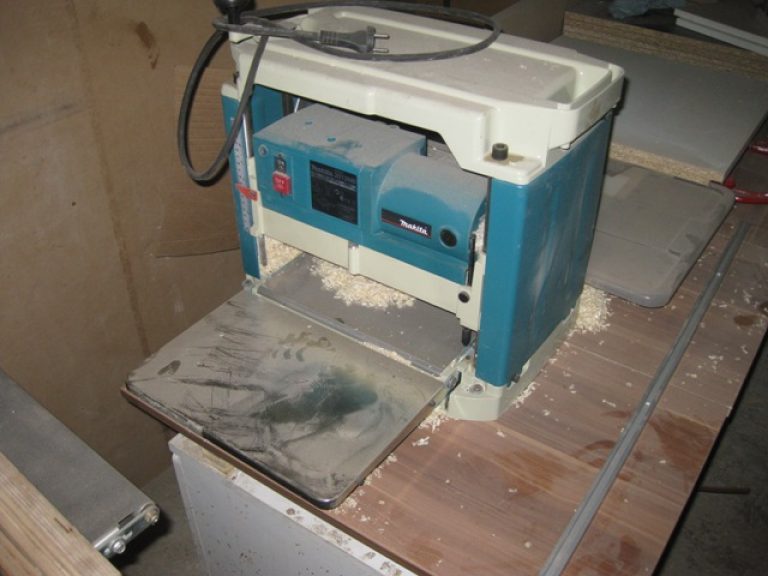
The maximum depth of cut in a single pass is 90 mm, while the greater depth of the studs (up to 240 mm with a width and height of 130 mm) can simply be achieved in several passes.
The machine can work with workpieces of unlimited length, for which an auxiliary block with adjustable geometric parameters is used. The machine itself is very compact and light: the dimensions in horizontal projection are 560 × 620 mm at a height of 810, the weight does not exceed 68 kg.
2.2 SCM Group, Italy
Under the Celaschi brand of the group, the Progress double-sided machine is now being produced, suitable not only for processing materials made of wood and its derivatives, such as chipboard, but also gypsum boards, plastic materials and fiberglass.
In addition to the main operation - the manufacture of spikes using cutters - it can perform cutting, profiling and other operations.

"Progress" can work with parts over 6 meters long and up to 20 centimeters thick with a material feed rate of up to 1 meter per second. It also has an automatic tool changer and CNC system, and can be easily integrated with other equipment from SCM Group.
2.3 MAGR Group of Companies, Ukraine
The product range includes a modern specialized milling machine model "SSh-200-160P", which is designed to perform the operation of cutting transverse spikes. Can be used in conjunction with trimming machines and presses for splicing PSD.
Performs batch processing of parts, which eliminates chips when cutting. The package is fixed using a pneumatic device, the offset of the spike pitch is carried out by changing the height of the desktop.
2.4 Savelovsky "SZDO", Russia
JSC "SZDO" offers high quality equipment, manufactured jointly with the world's leading companies producing equipment for wood processing. Tenoning machine "SHS"-3 is designed for cutting special wedge tenons on the ends of a wooden bar.
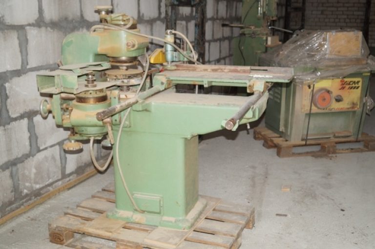
The machine provides the execution of a cycle of operations with the cutter offset by one second part of the step, for which a specialized pneumatic system from the Italian company Camozzi is used.
ShS-3 allows processing parts with dimensions of 20 x 20 centimeters with a thickness of up to 12 centimeters, a full cycle of cutting a spike on both sides takes no more than 30 seconds.
2.5 How to cut spikes with your own hands without using a machine?
In this case, you will need a tenoning device. Often, carpenters make homemade tenon cutters, but today you can purchase an industrial model, for example, “CMT” - 300. With it (if you have an electric router), you can use various templates to get the drawer groove you need.

To do this, you will also need the required size of the cutter, more precisely - an assortment of cutters from the same manufacturer. The CMT trademark belongs to the Italian corporation CMT Utensili SpA.
Often, grooving machines are used together with tenoning machines, for example, Balestrini 2 CAP.
When working with tenoning machines, it is necessary to use guards that prevent body parts and clothing from getting on moving parts, and follow the established safety rules when using electrical installations.
2.6 How does a homemade tenoning machine work? (video)