Maximum beam deflection. Questions about the deflection of wooden structures
For example, in the "Manual for the design of concrete and reinforced concrete structures made of heavy concrete ... (to SP 52-101-2003)" there is a calculation for the deflection of a reinforced concrete rectangular floor slab - a pivotally supported non-cantilever beam with dimensions h = 20 cm, b = 100 cm; h o = 17.3 cm; span l = 5.6 m; class B15 concrete (E b \u003d 245000 kgf / cm 2, R b \u003d 85 kgf / cm 2); tensile reinforcement class A400 (E s \u003d 2 10 6 kgf / cm 2) with a cross-sectional area A s \u003d 7.69 cm 2 (5 Ø14); total uniformly distributed load q = 7.0 kN/m. As a result of the calculation, the deflection of such a plate is f = 3.15 cm, which is more than the maximum allowable. The value of the maximum allowable deflection is determined in accordance with SNiP 2.01.07-85 "Loads and impacts". So for a floor slab in a residential building 5.6 m long, if there are no partitions under it, the maximum allowable deflection is f u \u003d l / 200 \u003d 560/200 \u003d 2.8 cm.
How to be in this case? Is it really possible to continue to storm the icy peaks of knowledge accumulated in the relevant normative documents, or is there still a simpler and shorter road to the goal? I think there is, but that's just my personal opinion.
The calculation below does not quite comply with the recommendations of SNiP 2.03.01-84 and SP 52-101-2003, however, it allows you to approximately determine the value of the deflection using a simplified method. And although a hinged non-cantilever single-span beam with a rectangular cross-sectional shape, on which a uniformly distributed load acts, is a special case against the background of many possible types of loads, design schemes and geometric shapes of the section, nevertheless it is a very common special case in low-rise construction.
An example of calculating the deformation of a reinforced concrete slab as beams of variable cross section
Deflection of the slab at selected calculation scheme will be
f = k5ql 4 /384EI p (321.1)
As you can see, the formula is quite simple and differs from the classical one by the presence of an additional coefficient. The coefficient k takes into account the change in the height of the compressed area of the section along the length of the beam under the action of a bending moment. With a uniformly distributed load and the work of concrete in the area of elastic deformations, the value of the coefficient for approximate calculations can be taken as k = 0.86. The use of this coefficient makes it possible to determine the deflection of a beam (plate) of variable section, as for a beam of constant section with a height h min. Thus, in the above formula, only 2 unknown quantities remain - design value the modulus of elasticity of concrete and the moment of inertia of the reduced section I p in the place where the height of the section is minimal. It remains only to determine this very moment of inertia, and the modulus of elasticity will be taken equal to the initial one.
For clarity, further calculation will be made for the plate mentioned above.
Theoretical prerequisites and assumptions taken when determining the deflection of a reinforced concrete slab operating in the area of elastic deformations
1. Since the ratio of the length of the plate to the height l/h = 560/20 = 28, i.e. is much greater than 10, then the effect of transverse forces on the deflection can be ignored.
2. The beam (plate) consists of materials with different moduli of elasticity, so the neutral line - the axis of the beam will not pass through the centers of gravity of the cross sections, but will be displaced and will pass through the given centers of gravity. The position of the given centers of gravity will depend on the ratio of the elastic moduli of concrete and reinforcement.
3. Since the modulus of elasticity of steel is much greater than the initial modulus of elasticity of concrete, then when considering the geometric parameters of the cross-section of the slab as a single section, the cross-sectional area of the reinforcement should be multiplied by the ratio E s /E b. For a slab, this ratio will be a s1 = 2000000/245000 = 8.163
Determination of the moment of inertia of the reduced section
4. On the support section of the slab, due to the small value of internal normal tensile stresses, the entire lower part of the section will work, i.e. and concrete and rebar. Since the moment of inertia of a conditionally compressed section (material - concrete) must be equal to the moment of inertia of a conditionally tensioned section (materials concrete and reinforcement), then with a rectangular cross-section (a constant value of the width b over the entire height of the section), the moments of inertia for conditionally compressed and conditionally stretched section with respect to the reduced neutral axis will be:
I c \u003d W c y \u003d 2by 3 / 3 \u003d b (2y) 3 / 12 \u003d I p \u003d 2b (h - y) 3 / 3 + 2As (ho - y) 2 E s / E b (321.2.1)
y 3 \u003d (h - y) 3 + 3A s (ho - y) 2 E s / bE b (321.2.2)
Note: own moment of inertia for reinforcing bars, due to its small value, we do not take into account to simplify calculations.
The solution of this equation for the slab under consideration will give the following result y o = 10.16 cm, which is logical in principle for the total height of the beam h = 20 cm. In principle, for approximate calculations, the value of the height of the compressed zone in sections without cracks can not be determined at all, According to the proposed method of calculation, the value of the height of the compressed zone in areas without cracks is only needed to assess the change in the height of the section along the length of the beam (based on this change, the value of the coefficient k is taken)
5. In the middle of the slab, where, as a result of the action of maximum normal stresses, the cracks will be maximum, only reinforcement will work in tension, the work of concrete can be neglected due to the low height of the stretched zone of the concrete section. With a difference in the resistance of concrete to compression and tension by 10 times, the difference in the heights of the compressed and tensile zones of concrete as a result of the formation of cracks will also be 10 times. In this case, the difference in the moments of inertia for such parts of the section will be 10 3 times.
6. The moments of inertia for the parts of the section in the middle of the plate will be:
I c \u003d W c y \u003d 2by 3 / 3 \u003d I p \u003d 2A s (ho - y) 2 E s / E b (321.2.3)
from which the following cubic equation can be derived:
y 3 \u003d 3A s (ho - y) 2 E s / bE b (321.2.4)
The solution of this equation for the considered plate will give the following result y l/2 = 6.16 cm.
Note: Sometimes if the value at with an accuracy of hundredths of a millimeter does not interest you, and the solution of cubic equations causes certain problems, then you can choose an approximate value at in 2-5 minutes, substituting this or that value in the equation (321.2.4) and looking at the results of the right and left parts.
7. Using this value of the height of the compressed zone for further calculations will be correct when concrete works in the area of elastic deformations (Fig. 321.a). If in the compressed zone, as a result of deformations, a redistribution of stresses occurs (Fig. 321.1.b), then the height of the compressed zone with this calculation method should be reduced:
Figure 321.1
8. Determine the height of the section, the minimum allowable strength calculations without taking into account plastic deformations.
Since the calculation of strength can be made from the condition
M/W ≤ R b ; W ≥ M / R b \u003d ql 2 / 8R b \u003d 7 560 2 / (8 85) \u003d 3228.23 cm 3 (321.3.1)
W = 2by 2 2 /3 (222.1.5.1)
then the deformations in the compressed zone of concrete will be elastic at
y 2 = (3W/2b) 1/2 = (3 3228.23/200) 1/2 = 6.96 cm (321.3.2)
9. Since the height of the compressed zone of concrete during the deformation process will be less than the height required for a linearly changing distribution of normal stresses along the height (the difference is shown in Figure 321.1.b by a white rectangle), this will lead to a redistribution of normal stresses (a similar redistribution is shown in Figure 321 .b) rather conditionally). As a result, the area of the diagrams in both cases will be the same (since the value of the bending moment does not change), and the height of the elastic deformation zone will still decrease by y 2 - y. Thus, the calculated value of the height of the reduced section will be:
h min \u003d y p \u003d y - (y 2 - y) \u003d 6.16 - (6.96 - 6.16) \u003d 5.36 cm (321.4)
10. The calculated moment of inertia will be
I calc \u003d 2by p 3 / 3 \u003d 2 100 5.36 3 / 3 \u003d 10266 cm 4 (321.5)
11. The deflection value at full load will be
f = 0.86 5 7 560 4 / (384 245000 10266) = 3.065 cm (321.6)
12. Requirement of SNiP 2.01.07-85:
f = 3.065 cm ≤ f u = 2.8 cm (321.7)
not observed. And this means that in order to comply with the requirements, it is necessary either to increase the class of concrete, or to increase the cross section of the reinforcement, or to increase the height of the section. However, all this is not directly related to the calculation of the deflection.
Note: One of the disadvantages of the above method for determining the deflection is that in the calculations we did not take into account the possible change in the modulus of elasticity under prolonged load and various other factors. It cannot be said that a more accurate account of the modulus of elasticity will bring terrible confusion into the orderly series of deflection, however, the calculation, taking into account the refined value of the modulus of elasticity, will be more accurate.
Deflection is determined only for the action of permanent and long-term loads with a load safety factor >according to the formula on page 142:
![]() , where
, where
for a freely supported beam, the coefficient is:
With a uniformly distributed load;
With two equal moments at the ends of the beam from the compression force.
The total curvature of the slab in areas without cracks in the tension zone is determined by the formulas (155 ... 159) p.4.24.
Curvature from constant and long-term load:
The moment from the corresponding external load about an axis normal to the plane of action of the bending moment and passing through the center of gravity of the reduced section;
Coefficient taking into account the influence of long-term creep of heavy concrete at a moisture content of more than 40%;
Coefficient taking into account the influence of short-term creep of heavy concrete;
Curvature from short-term bending under the action of the pre-compression force, taking into account:
Since the compression stress of the top fiber concrete
those. the upper fiber is stretched, then in the formula when calculating the curvature due to the bending of the slab due to shrinkage and creep of concrete from the pre-compression force, we take the relative deformations of the extreme compressed fiber . Then according to formulas (158, 159):
Deflection from constant and prolonged loads will be:
Conclusion: The deflection does not exceed the limit value:
1.4 Slab design
The main working reinforcement of the slab is prestressed reinforcement 3 Æ12 made of class A-VI steel, determined by calculation according to normal sections and laid in the zone of the slab stretched from the action of operational loads.
The upper shelf of the slab is reinforced with a C-1 mesh of B500 class wire. The transverse ribs are reinforced with Kr-1 frames in the supporting sections at a length of l / 4; frame Kr-1 includes longitudinal working rods ø4 B500 and transverse rods
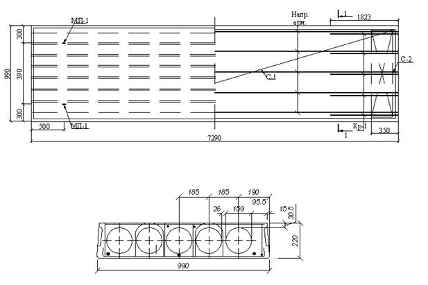
Figure 5- To the calculation of the slab: formwork and reinforcement scheme
4øBp-I in 100mm increments (ensuring sloping strength). To reinforce the concrete of the support zone of the slab, C-2 meshes of B500 class wire are laid.
2 Calculation and design of the column
For columns, concrete of classes in compressive strength not lower than B15 is used, for heavily loaded ones not lower than B25. The columns are reinforced with longitudinal rods with a diameter of 12-40 mm, mainly from hot-rolled steel of class A400 and transverse rods from hot-rolled steel of classes A400, A300, A240.
2.1. Initial data
The load per 1 m2 of the floor is assumed to be the same as in the previous calculations, the load per 1 m2 of the floor is given in Table 2.
Place of construction - Moscow, III snow district.
table 2
|
Type of load |
Reliability factor by load |
||
|
Waterproofing carpet 4 layers Reinforced cement screed d=40 mm, r=22 kN/m3 Foam glass d=120 mm, r=300 kg/m3 Expanded clay on a slope d=100 mm, r=1200 kg/m3 Vapor barrier 1 layer Hollow-core floor slab with monolithic seams d=220 mm |
| ||
Reinforced concrete hollow core floor slabs are manufactured in accordance with GOST 9561-91 and are used to cover spans of residential and public buildings.
Almost no building is complete without the use of these products. If for the arrangement of foundations for FBS concrete blocks there is an equivalent replacement in the form of a flood foundation, pile foundation, etc., then there is practically no alternative to hollow core floor slabs. Any other solutions (monolithic reinforced concrete structures or wood floors) are inferior either in strength or in ease of manufacture.
From this article you will learn:
- what is the difference between PC boards and PB boards,
- how to calculate the allowable load on the panel,
- what causes floor slab deflections and what to do about it.
Differences between hollow core slabs PC and PB
AT last years PB floor slabs put into circulation back in Soviet times are being replaced by new generation products - hollow bench panels of formless molding of the PB brand (or PPS, depending on the project).
If PC reinforced concrete slabs are manufactured according to the drawings of the 1.141-1 series, then there is no single document on the basis of which bench panels are produced. Typically, factories use shop drawings provided by equipment suppliers. For example, series 0-453-04, IZH568-03, IZH 620, IZH 509-93 and a number of others.
We have summarized the main differences between PC and PB boards in one table.
| PC | PB |
|---|---|
| Thickness | |
| 220 mm or 160 mm for lightweight PNO boards | From 160 mm to 330 mm depending on the project and required length |
| Width | |
| 1.0; 1.2; 1.5 and 1.8 meters | Most often there are 1.2, but there are also stands with a width of 1.0 and 1.5 meters |
| Length | |
| For lightweight PNO up to 6.3 meters with a certain step, individual for each manufacturer. For PC - up to 7.2 less often up to 9 meters. | Since the plates are cut to length, it is possible to manufacture right size on request in 10 cm increments. The maximum length can be up to 12 meters depending on the height of the panel. |
| Typical 800 kgf/m2, under the order it is possible to manufacture with a load of 1250 kgf/m2 | Although most often it is the load of 800 that is produced, but the technology makes it possible to make plates and any other from 300 to 1600 kgf / m2 without additional costs. |
| Smoothness and evenness | |
| Still, the technology is old and everyone’s forms are already worn out, you will not find ideal plates, but frankly bad ones are rare. By appearance for a solid 4. | They are made on the latest stands, smoothed out by an extruder. As a rule, plates look much better, although individual exceptions are possible. |
| Reinforcement | |
| Up to a length of 4.2 - a simple mesh, longer panels are made prestressed, because. the use of tension allows you to achieve the required grade of strength at a lower cost. | Prestressed at any length. Depending on the project, both 12k7 or 9k7 ropes and VR-1 wire can act as strings. |
| Concrete brand | |
| M-200 | From M-400 to M-550 |
| Hole sealing | |
| Usually done at the factory. If you have not done it, be sure to pour concrete M-200 | The sealing of the holes is not required, since the design provides for the sufficiency of the strength of the end sides without additional reinforcement |
Load on hollow core slabs
In practice, the question often arises of what kind of load a reinforced concrete hollow core slab can carry, whether it will break from one or another stress.
In any case, a load-bearing wall should not rest on it. Capital (bearing) walls can be based strictly either on foundation blocks or on the same walls of the lower floors.
Where the panel overlaps the load-bearing wall, it is additionally strengthened - the holes of the voids are filled with concrete from the ends, and it is not recommended to overlap more than 100 mm on the sides, i.e. up to the 1st void.
The load can be distributed or point. For a distributed load, everything is simple - calculate the area of \u200b\u200bthe slab in m2, multiply by the load according to the marking (usually 800 kg / m2) and subtract the own weight of the slab. So for PC 42-12-8 we have an area = 5m2. Multiply by 800 = 4 tons. And subtract own weight = 1.53 tons. The remaining 2.5 tons will be acceptable distributed load. You can, for example, fill it with a concrete screed of 20 cm.
For point loads, it is difficult to make a similar calculation, since the bearing capacity of the plate in the case of point pressure depends not only on the weight of the body, but also on the point of application. So along the edges of the panel is much stronger than in the center. It is usually recommended not to exceed the rated load by more than 2 times, i.e. up to 1.6 tons in the absence of other influences.
In practice, it is more often necessary to calculate the combined load from different sources, such as screed, furniture, people, non-load-bearing partitions. Here one should trust the experience of Soviet research institutes, which accepted the standard load of "8", i.e. sufficient for all "standard" use cases.
Their calculations are based on the following considerations:
- own weight = 300 kg/m2
- screed + poured floors = 150 kg / m2 (approximately 6-7 cm.
- furniture + people = 200 kg/m2
- walls/partitions = 150 kg/m2
If in your case these figures are significantly exceeded, it may be worth considering purchasing panels with higher bearing capacity.
Hollow-core floor slabs, due to the reinforcement and properties of concrete, distribute the weight of the object pressing on them over a larger surface than the actual contact area. So, for example, if your partition has a width of 100 mm, and there are no other loads near it, then this pressure will be distributed over larger surface and will not go beyond the limits laid down in the calculations of marginal norms.
It should also not be forgotten that in addition to constant (static) loads, there are also variable (dynamic) loads. For example, a weight standing on the floor will have a much less destructive effect than a weight that has fallen from a cabinet. Therefore, dynamic loads on the panel should be avoided whenever possible.
Floor slab deflections
Sometimes buyers are faced with a situation where reinforced concrete floor slabs have different deflections, including in the opposite direction. You should be aware that according to SNiP 2.01.07-85 “Loads and Impacts”, a deflection of more than 1/150 of the length of the product is not a defect. So for the most problematic PB 90-12, the allowable deflection is as much as 6 cm.
Reverse deflection is most often formed when sawing off the last PB floor slab on the stand, when its length is significantly less than the length range for which the stand was originally prepared. For longer slabs, more tension is given and as the main reinforcement goes along the bottom surface of the slab; when sawing off a short slab, this excess compression force, as it were, bends the slab.
To avoid this situation, buyers should carefully inspect the products before purchasing. Usually, reinforced concrete slab with a large deflection is not difficult to notice in a stack of others hollow core slabs. It must be admitted that these cases are still rare and good producers practically do not occur.
The answer to the question about the permissible support of panels on walls can be found in our article.
If the construction of a two-story or one-story house, but with a basement or attic, it is necessary to correctly calculate and build interfloor ceilings. Let's consider the stages and nuances of the overlap according to wooden beams and we will calculate the sections of beams that provide sufficient strength.
The device of interfloor ceilings needs special attention, because made "by eye", they may not withstand the loads on them and collapse, or require unnecessary, unreasonable costs. Therefore, one or more options. The final decision can be made by comparing the cost or availability of acquiring materials.
Requirements for interfloor ceilings
Interfloor ceilings must withstand constant and variable loads, that is, in addition to their own weight, withstand the weight of furniture and people. They must be sufficiently rigid and not allow the maximum deflection to be exceeded, provide sufficient noise and heat insulation.

Specific loads from furniture and people for living quarters are taken in accordance with the standards. However, if you plan to install something massive, such as a 1000 l aquarium or a natural stone fireplace, this must be taken into account.
The rigidity of the beams is determined by calculation and is expressed in the allowable bending per span. Permissible bending depends on the type of flooring and the flooring material. The main limit deflections determined by SNiP are shown in Table 1.
Table 1
|
Structural elements |
Limit deflections in span fractions, no more |
|
1. Beams of floors |
1/250 |
|
2. Beams of attic floors |
1/200 |
|
3. Coatings (except valleys): |
|
|
a) runs, rafter legs |
1/200 |
|
b) cantilever beams |
1/150 |
|
c) trusses, glued beams (except for cantilever beams) |
1/300 |
|
d) plates |
1/250 |
|
e) battens, flooring |
1/150 |
|
4. Bearing elements of valleys |
1/400 |
|
5. Panels and fachtop elements |
1/250 |
|
Notes: 1. In the presence of plaster, the deflection of the floor elements only from a long-term temporary load should not exceed 1/350 of the span. 2. In the presence of a construction lift, the maximum deflection of glued beams can be increased up to 1/200 of the span. |
|
Please note that flooring as ceramic tiles or concrete screed, which is prone to cracking, can further tighten the requirements for allowable deflection, especially with sufficiently long spans.
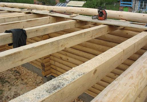
To reduce the loads on the beams, if possible, they should be placed parallel to the short walls, with the same pitch. The maximum span when covered with wooden beams is 6 m.
Types of floors
According to the purpose of the overlap are divided into:
interfloor;
attic;
· basement (basement).
Their design features are allowable loads and the device of steam and thermal insulation. If the attic is not intended for living or storing massive objects, variable loads can be reduced to 50-100 kg / m 2 when calculating the deflection.
Thermal insulation between two residential floors may seem redundant, but sound insulation is a desirable parameter for the majority, and this is achieved, as a rule, with the same materials. It should be taken into account that attic and basement floors need a thicker layer. thermal insulation material. Film material for vapor barrier in the attic floor should be located under the insulation layer, and in the basement - above it. To prevent the occurrence of dampness and damage to structures by a fungus, all rooms must be equipped with ventilation.
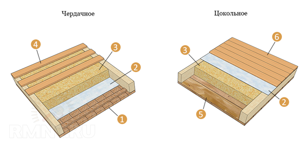
Floor options: 1 - plank shield; 2 - vapor barrier; 3 - thermal insulation; 4 - sparse flooring; 5 - boards; 6 - flooring
The design of the floors can also be different:
· with open and hidden beams;
· With various types bearing beams;
· With different materials filling and lining of the floor.
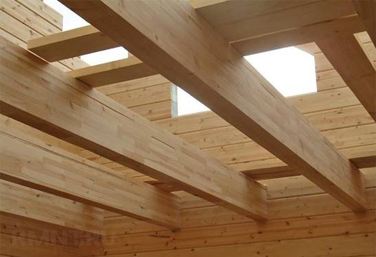
Hidden beams are sewn on both sides and are not visible. Open - protrude from the ceiling and serve as decorative elements.
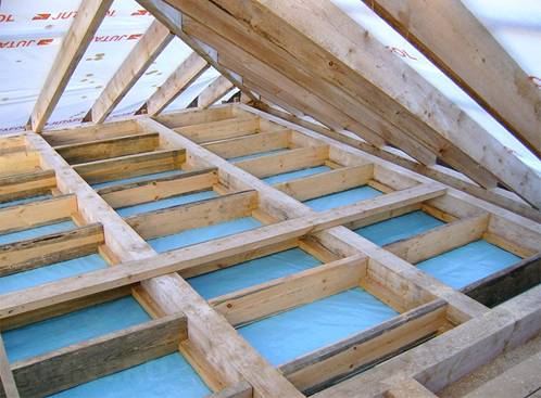
The figure below shows what the structure of the overlap can be. attic floor with a shield roll and with a filing of boards.
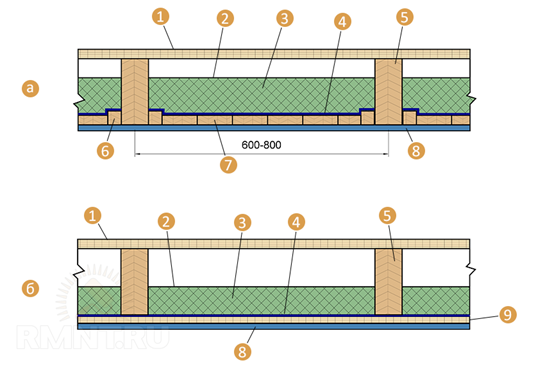
a - with a shield roll; b - with filing from boards; 1 - plank floor; 2 - polyethylene film; 3 - insulation; 4 - vapor barrier; 5 - wooden beams; 6 - cranial bars; 7 - shield reel; 8 - finishing; 9 - filing from boards
Types of fastenings and connections of wooden beams
Depending on the design and material of the load-bearing walls, wooden beams are attached:
· in the nests provided in the brick or block masonry, deepening the beam or log at least 150 mm, and the board at least 100 mm;
· on the shelves (ledges) provided in the brick or block masonry. It is used if the wall thickness of the second floor is less than the first one;
· into cut grooves in log walls to a depth of at least 70 mm;
· to the beam of the upper strapping of the frame house;
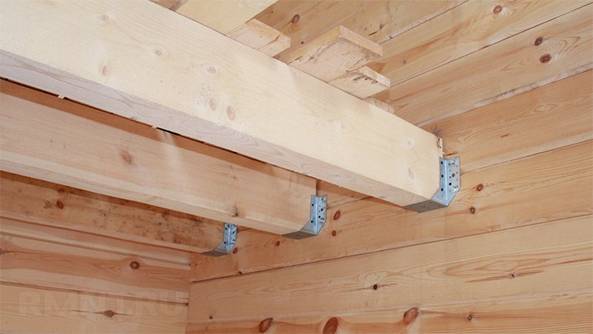
· to metal supports-brackets fixed on the walls.
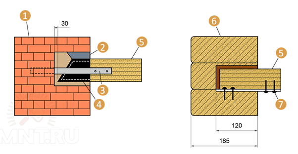
1 - support on brick wall; 2 - solution; 3 - anchor; 4 - roofing felt insulation; 5 - wooden beam; 6 - support on a wooden wall; 7 - bolt
If the length of the beam is not enough, you can lengthen it by connecting (joining) along the length using one of the known methods using wooden pins and wood glue. When choosing the type of connection, be guided by the direction of application of the load. It is desirable to strengthen the spliced beams with metal plates.
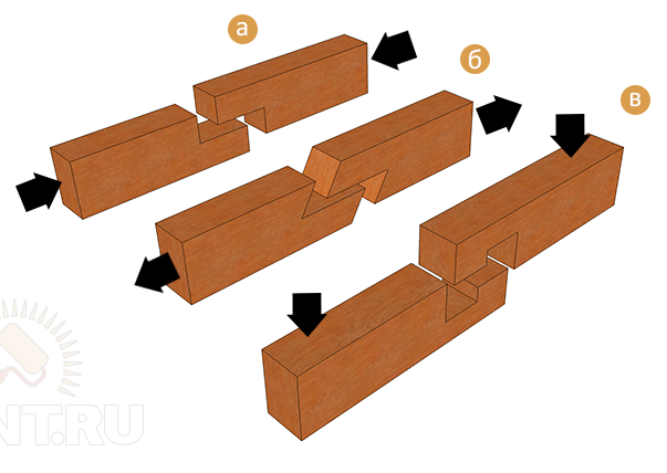
a - compression; b - stretching; c - bend
About wooden beams
In construction, beams of rectangular, round or partially round section are used. The most reliable are rectangular lumber, and the rest are used in the absence of timber or for reasons of economy, if such materials are available on the farm. Glued wood materials have even greater strength. Beams made of glued beams or I-beams can be installed on spans up to 12 m.
The most inexpensive and popular type of wood is pine, but other types of conifers are also used - larch, spruce. Floors are made of spruce in summer cottages, small houses. Larch is good for building premises with high humidity (bath, swimming pool in the house).
Materials also differ in grade, which affects bearing capacity beams. Grade 1, 2 and 3 (see GOST 8486–86) are suitable for floor beams, but grade 1 for such a design may be unnecessarily expensive, and grade 3 is best used on small spans.
Calculation of load-bearing beams
To determine the section and step of the beams, it is necessary to calculate the load on the ceiling. The collection of loads is carried out according to the methodology and taking into account the coefficients set forth in SNiP 2.01.07–85 (SP 20.13330.2011).
Load calculation
The total load is calculated by summing the constant and variable loads, determined taking into account the standard coefficients. In practical calculations, they are first set by a certain design, including the preliminary layout of beams of a certain section, and then corrected based on the results obtained. So the first step is to sketch all the layers of the "pie" overlap.
1. Own specific gravity of the overlap
The specific gravity of the floor is the sum of its constituent materials and is divided by the horizontal total length of the floor beams. To calculate the mass of each element, you need to calculate the volume and multiply by the density of the material. To do this, use table 2.
table 2
|
Material name |
Density or bulk density, kg / m 3 |
|
asbestos cement sheet |
|
|
Basalt wool (mineral) |
50–200 (depending on the degree of compaction) |
|
Birch |
620–650 |
|
Concrete |
2400 |
|
Bitumen |
1400 |
|
Drywall |
500–800 |
|
Clay |
1500 |
|
Chipboard |
1000 |
|
Oak |
655–810 |
|
Spruce |
420–450 |
|
Reinforced concrete |
2500 |
|
Expanded clay |
200–1000 (from foam factor) |
|
Expanded clay concrete |
1800 |
|
Brick solid |
1800 |
|
Linoleum |
1600 |
|
Sawdust |
70–270 (depending on fraction, wood type and humidity) |
|
Parquet, 17 mm, oak |
22 kg/m2 |
|
Parquet, 20 mm, panel |
14 kg/m2 |
|
foam concrete |
300–1000 |
|
Styrofoam |
|
|
Ceramic tiles |
18 kg/m2 |
|
Ruberoid |
|
|
Wire mesh |
1.9–2.35 kg/m2 |
|
Pine |
480–520 |
|
Carbon steel |
7850 |
|
Glass |
2500 |
|
glass wool |
350–400 |
|
Plywood |
|
|
cinder block |
400–600 |
|
Plaster |
350–800 (from composition) |
For wood materials and waste density depends on humidity. The higher the humidity, the heavier the material.
Permanent loads include partitions (walls), specific gravity which is taken approximately 50 kg / m 2.
The decor of the room, people, animals - all this is a variable load on the floor. According to Table. 8.3 SP 20.13330.2011, for residential premises, the standard distributed load is 150 kg / m 2.
The total load is not determined by simple addition, it is necessary to take the reliability factor, which, according to the same SNiP (clause 8.2.2), is:
· 1,2 - with a specific gravity of less than 200 kg/m 2 ;
· 1.3 - with a specific gravity of more than 200 kg / m 2.
4. Calculation example
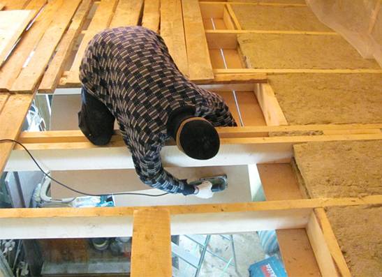
As an example, let's take a room with a length of 5 and a width of 3 m. Every 600 mm of length we put beams (9 pcs.) Of pine with a section of 150x100 mm. We will block the beams with a board 40 mm thick and lay linoleum 5 mm thick. From the side of the first floor, we will sew the beams with plywood 10 mm thick, and inside the ceiling we will lay a layer of mineral wool 120 mm thick. Partitions are absent.
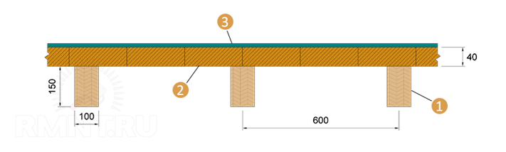
1 - beam; 2 - board; 3 - insulated linoleum 5 mm
The calculation of the constant specific load on the area of the room (5 x 3 \u003d 15 m 2) is shown in table 3.
Table 3
|
Material |
Volume, m3 |
Density, kg / m 3 |
Weight, kg |
|
|
Beam (pine) |
9 x 0.15 x 0.1 x 3.3 = 0.4455 |
222,75 |
14,85 |
|
|
Board (pine) |
15 x 0.04 = 0.6 |
20,0 |
||
|
Plywood |
15 x 0.01 = 0.15 |
|||
|
Linoleum |
15 x 0.005 = 0.075 |
1600 |
||
|
mineral wool |
15 x 0.12-0.405 = 1.395 |
139,5 |
||
|
Total: |
58,15 |
|||
|
Taking into account k = 1.2 |
Design load on the beam (qр) - 250 x 0.6 m = 150 kg/m (1.5 kg/cm).
Allowable deflection calculation
We accept the permissible deflection of the interfloor ceiling - L / 250, i.e. for a three-meter span, the maximum deflection should not exceed 330 / 250 = 1.32 cm.
Since the beam lies on the support at both ends, the calculation of the maximum deflection is carried out according to the formula:
· h = (5 x qp x L4) / (384 x E x J)
where:
· L - beam length, L = 330 cm;
· E - modulus of elasticity, E \u003d 100,000 kg / cm 2 (for wood along the fibers according to SNiP);
· J is the moment of inertia, for a rectangular beam J = 10 x 153/12 = 2812.5 cm 4.
For our example:
· h \u003d (5 x 1.5 x 3304) / (384 x 100000 x 2812.5) \u003d 0.82 cm
The result obtained in comparison with the allowable deflection has a margin of 60%, which seems excessive. Therefore, the distance between the beams can be increased by reducing their number and repeat the calculation.
In conclusion, we suggest watching a video on calculating the floor on wooden beams using a special program:
http://www. rmnt . ru/ - RMNT website. en