Resistance of 220 volt incandescent lamps. Schematic diagram of an incandescent lamp dimmer. Online calculators for determining the value of resistors by color coding
Page 1
The resistance of light bulbs designed to operate at the same voltage is inversely proportional to their power.
The resistance of incandescent bulbs depends on the voltage of the bridge. The ratio between the elements of the bridge is chosen in such a way that with a slight change in the voltage at its input, the voltage at the output remains practically constant.
Voltage, current and resistance. As mentioned earlier, the number of electrons in motion in a circuit is called current, and it is measured in amperes. The "voltage" that pushes the electrons along is called voltage and is measured in volts. If you live in the United States, the power supplies in the wall of your house or apartment deliver 120 volts each.
If you know the amps and volts involved, you can determine the amount of electrical power being consumed, which we usually measure in watt hours or kilowatt hours. Imagine that you are plugging a heater into a wall outlet. You measure the amount of current flowing from the wall outlet to the heater and it goes up to 10 amps. If you multiply voltage by amps, you get power. This is true for any electrical appliance. If you plug in a light and it drives half the amp, it's a 60 watt light bulb.
The resistance R of the bulb changes when heated from 30 to 300 ohms. How much does the potential difference U on the bulb change in this case, if the movable contact c is in the middle of the potentiometer. By how much does the power P consumed by the bulb change in this case.
Find the resistance of a flashlight bulb using the data written on its base.
Examples from the practice of measuring the resistance of products
Let's say you turn on the heater and then look at the power meter outside. The purpose of the meter is to measure the amount of electricity coming into your home so that the power company can bill you. Let's assume we know that it's unlikely that nothing else is going on in the house, so the meter only measures the electricity used by the space heater.
Your space heater uses 2 kilowatts. If you leave the heater on for one hour, you will use 2 kilowatt hours of electricity. If your power company charges you 10 cents per kilowatt hour, then the power company charges you 12 cents for every hour you leave your heater.
Problem 15.1. At a temperature of 20 C, the resistance of a light bulb with a tungsten filament is 2 ohms, in a heated state - 16 6 ohms.
If u: m1 [) and the resistance of the bulb in the cold state and then turn it on in the circuit direct current, then the devices will notice a deviation from Ohm's law and, moreover, the greater the greater the current strength. The difficulty in proving the validity of Ohm's law disappears, but take into account the dependence of resistance on temperature R R0 (la /), where the temperature coefficient a is positive for some substances, and negative for others.
Light bulb color
Now let's add another factor to current and voltage: resistance, which is measured in ohms. We can extend the analogy to understand resistance. Voltage is equivalent to water pressure, current is equivalent to flow rate, and resistance is similar to pipe size.
A basic electrical engineering equation called Ohm's law explains how the three terms relate. Current equals voltage divided by resistance. If you increase the pressure in the tank, more water comes out of the hose, right? The same applies to electrical system: Increasing the voltage will result in more current. Now say you're increasing the diameter of the hose and all tank fittings. This adjustment will also cause more water to come out of the hose. It's like lowering the resistance in an electrical system, which increases the current.
With an increase in the output voltage of the exciter, for some reason, the current in the negative feedback circuit increases, which leads to an increase in the resistance of the light bulb, an increase in the voltage drop across it, and, accordingly, an increase in negative feedback. As a result output voltage remains unchanged.
When you look at an ordinary incandescent light bulb, you can see this water analogy in action. The filament of a light bulb is an extremely thin wire. This thin wire opposes the flow of electrons. You can calculate the wire resistance with the resistance equation.
UPD: Fluorescent lamp filament resistance
Let's say you have a 120W light bulb plugged into an outlet. The voltage is 120 volts and a 120 watt bulb has 1 amp going through it. You can calculate the resistance of a filament by rearranging the equation. Thus, the resistance is 120 ohms.
The high-frequency power of the keyae-bans to be measured is supplied to an incandescent bulb (or a group of bulbs), and attention is paid to matching the resistance of the bulbs with the characteristic impedance of the feeder supplying high-frequency energy (see Matched load), since otherwise the reflection of the high-frequency part energy from the load will not make it possible to make an accurate measurement. The light emitted by the light bulb (or bulbs) falls on the photocell, as a result of which the pointer of the DC electrical measuring instrument of the magnetoelectric system in the photocell circuit deviates. The deviation of the needle will depend on the power heating the filament of the light bulb, and the device can be calibrated directly in units of power.
Beyond these basic electrical concepts, there is a practical difference between the two kinds of current. Some current is direct and some current is alternating - and this is a very important difference. Simply connect the positive terminal of the battery to one electrical terminal of your light bulb and the negative terminal to the other electrical terminal of the lamp. Many lamps have one electrical contact with a screw thread on it, and the other contact is a round dot at the end of the base. Other bulbs will have metal ends.
It is notoriously difficult to get good electrical contact on batteries and lamps when soldering wire. Spring contacts in flashlights work much better. It is important to choose a light bulb that matches what the battery can drain. If the battery voltage is too low, the current flowing through the bulb will be small and the incandescent bulb will not get hot enough to glow noticeably. high voltage, so much current will flow that the filament accumulates and evaporates.
The power of high-frequency oscillations to be changed is supplied to an incandescent bulb (or a group of bulbs), and attention is paid to matching the resistance of the bulbs with the characteristic impedance of the supply feeder. The light from the bulb falls on the photocell, as a result of which the arrow of the electrical measuring device in the photocell circuit deviates. The device can be calibrated directly in units of power.
Standard lamps are designed to operate at about 120 volts, which is an unusual range for batteries. Regular incandescent bulbs are designed to run at about 3V, which is easy to get with two batteries in series. Light bulbs from automobiles are usually designed to operate with approximately 12 volts, a car battery output, or eight standard battery cells.
You might think that using a lower voltage would only dim the light slightly, but the effect is actually much more severe. First, the heating power in the lamp goes like the square of the voltage, at least until the voltage is large enough to heat up the lamp and increase its resistance. Secondly, the amount of visible light produced in the bulb is practically zero until the filament temperature approaches the standard operating temperature. Thus, using one fourth of the power will give much less than one quarter of the light output.
- This is a measuring device used to determine the amount of resistance in circuits. Resistance is measured in Omaha and is denoted by the Latin letter R. About what Ohm is in a popular form Before starting measurements with an ohmmeter, I strongly recommend that you read the article on the site "Current Law".
If you use too low a voltage, the light bulb will glow orange because it can still emit several colors of light, but not the blue part of the spectrum. This is because your temperature is too low to give off visible light.
Follow-up #1: Battery powered light bulbs
The light you give off is infrared, which can be detected but not directly by the eyes. Of course, any arrangement of batteries providing the correct voltage will do. Twisting 120V batteries leaves a very dangerous voltage, easy enough to kill someone without the proper safety provided by standard plugs and plugs. The headlights in a car are exactly what you want - about 50 watts per second, and two of them, which are driven in parallel on a 12-volt car battery.
Measuring device An ohmmeter is structurally a battery with a series-connected pointer or digital indicator. In practice, an instrument that only measures resistance is used for special cases, such as measuring insulation resistance at elevated voltage, earth resistance, or as a reference for the verification of other measuring instruments. All combined instruments - testers and multimeters have the function of measuring resistance.
The dependence of the resistance of the filament of an incandescent lamp on voltage
You can easily find 40W halogen bulbs at most hardware stores that run on 12 volts of electricity. They can also come in higher power. Regular alkaline batteries may not deliver 75 watts for a very long time - a good car battery will last much longer.
Follow-up #2: Switches and Batteries
As long as the switch is not connected to the 220V mains and also to the battery, you are fine. If you are using a high voltage battery, you can blow through a low voltage lamp. You can also burst a light bulb by throwing the battery into it, but that's probably not what you had in mind.

On electrical measuring circuits, an ohmmeter is denoted by the Greek letter omega enclosed in a circle, as shown in the photo.
Repair of electrical wiring, electrical and radio engineering products consists in finding the contact of current conductors with each other. In some cases, the resistance must be equal to infinity, for example, insulation resistance. And in others it is equal to zero, for example, the resistance of wires. And in some cases it is equal to a certain value, for example, the resistance of the filament of a light bulb or a heating element.
Is there any possibility that this might work? - Chris Windsor, Ontario, Canada. These compact fluorescent lamps intended for use with power supply alternating current rather than with DC battery power. The DC/DC converter will add significant weight.
This is safe as there are no high voltages anywhere in the circuit. It may be convenient to start with a commercially available lamp driven by 12 V DC, which can be supplied with about 8-10 alkaline cells. You can measure the actual voltage to check.
Attention! It is allowed to measure the resistance of circuits, in order to avoid failure of the Ohmmeter, only when they are completely de-energized. It is necessary to remove the plug from the socket or remove the batteries from the compartment. If the circuit contains electrolytic capacitors of a larger capacity, then they must be discharged by shorting the capacitor leads through a resistance of about 100 kOhm for a few seconds.
Follow-up #5: Efficient Lighting
We have 12-12 rabbits in our backyard. Every night she comes out to feed and water them in the dark with a flashlight. Do I need an inverter or buy some kind of lamp? You can use an inverter, but that would be inefficient. Compact fluorescent lamps will work fine if you connect 115V AC. However, the battery system avoids any safety issues.
I was wondering how many batteries would it take to power a 120 or 230 volt light bulb? Weird, we suddenly had problems. The wire runs from one battery terminal to one side of the single pole single pole switch. One should also be noted. Go to the battery side and - go to the battery side.
As with voltage measurements, before measuring resistance, it is necessary to prepare the device. To do this, you need to set the switch of the device to the position corresponding to the minimum measurement of the resistance value.
Before measurements, you should check the operability of the device, as there may be bad batteries and the device may not work. To do this, connect the ends of the probes together.
Follow-up #9: Auto lamp battery size?
Oops, here "lead" is just a wire coming from a device - a switch, etc. there are light bulbs designed for automotive use that work well with 12 volt batteries. Most cars run on a 12 volt system, so most bulbs are rated for the same. So you need a 12 volt battery or two 6 volt batteries connected in series.
Follow-up #10: Snowboarding
So you end up with something light, simple, durable and efficient, all of which are useful properties for these portable handheld devices. You probably want something light. Headlights can run parallel to each other, in a circuit where the switches and battery are in series.
At the same time, the arrow of the tester should be set exactly to the zero mark, if it has not been set, then you can turn the “Set. 0". If it doesn't work, you need to replace the batteries. For dialing electrical circuits, for example, when checking an electric incandescent bulb, you can use the device, the batteries are dead on the battery and the arrow is not set to 0, but it reacts at least a little when the probes are connected. It will be possible to judge the integrity of the circuit by the fact of the deviation of the arrow. Digital instruments should also show zero readings, a deviation in tenths of ohms is possible, due to the resistance of the probes and the transient resistance in the contacts for connecting them to the terminals of the device.
Follow-up #12: Body lighting?
It is difficult to use our system to draw a diagram. Similar to interesting idea! Be sure and try something other than a real body first and don't use a higher voltage than the battery.
Follow-up #13: 3-volt lamp on a 9-volt battery
It will work fine for a day or so, but after that it will light up and then quickly disappear. Is it better to have the bulb a little over your battery voltage, or a little under? The ratio in your case is 2~.With the ends of the probes open, the arrow should be set to the point indicated on the ∞ scale, and in digital instruments, the overload will flash or the number 1 will be displayed on the indicator on the left side.
The ohmmeter is ready to go. If you touch the ends of the probes to the conductor, then if it is intact, the device will show zero resistance, otherwise, the readings will not change.
So this naive model predicts that a 9 volt battery will last twice as long if two batteries have the same amount of stored energy. Now this is probably not the case because the resistance of the lamp will probably increase a little as it gets hotter with a 9 volt battery. It may be worth connecting a small resistance in series with the light bulb. It will dim a little and the battery will last a little longer.
Follow-up #17: Battery powered
Thank you, Chris Staten, New York Island. This is a normal incandescent lamp. For your incandescent bulbs, you can connect anyway. Based on the previous answer, I need a car battery. It's frustrating to assemble a battery to power it. It's safer and more convenient.

If the multimeter has a circuit continuity function, indicated in the resistance measurement sector by the symbol of a diode, then it is easier to measure the resistance of wires in a cable and in low-resistance circuits by setting the mode switch to this position. Then the test will be accompanied by a sound signal, and it will not be necessary to constantly look at the display of the device.
Examples from the practice of measuring the resistance of products
Theoretically, everything is usually clear, but in practice questions often arise that are best answered by examples of checking the most common products with an ohmmeter.
Checking incandescent bulbs
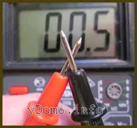
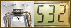
The incandescent bulb in the lamp or in the car on-board instruments has stopped shining, how to find out the reason? The switch, electrical socket, or electrical wiring may be faulty. With the help of a tester, any incandescent lamp from a home lamp or car headlight, filament of fluorescent lamps and energy-saving lamps is easily checked. To check, it is enough to set the switch of the device to the position of measuring the minimum resistance and touch the ends of the probes to the terminals of the light bulb base.

The resistance of the filament of the light bulb was 51 ohms, which indicates its serviceability. If the thread were broken, then the device would show infinite resistance. The resistance of a 220 V halogen bulb with a power of 50 watts when lit is about 968 ohms, a 12 volt car bulb with a power of 100 watts, about 1.44 ohms.
It is worth noting that the resistance of the filament of an incandescent lamp in a cold state (when the light bulb is not lit) is ten times less than when it is heated. It's connected with physical property tungsten. Its resistance increases non-linearly with heating. Therefore, incandescent lamps, as a rule, burn out at the moment of switching on.
Using the online calculator, you can independently calculate the resistance of any incandescent light bulb or heating element, for example, heating element, electric soldering iron.
Checking the Headphones of the Headset
It happens that the headphones in one of the emitters, or in both at once, the sound is distorted, periodically disappears or is absent. Two options are possible here, either the headphones are faulty, or the device from which the signal is taken. Using an ohmmeter, it is easy to check what is the cause and locate the fault. To test the headphones, you need to connect the ends of the probes to the connector, usually the headphones are connected to the equipment using a 3.5 mm jack connector. In this connector, the contact, which is closer to the holder, is common, at the end it is figured for the left channel, between them there is an annular contact for the right channel.
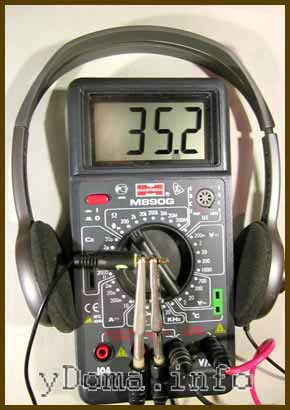
One end of the probe is touched to a common conclusion, and the second in turn to the other two. The resistance should be the same and be about 40 ohms. Usually, the impedance is indicated in the passport for headphones. If the resistance is very different, then there may be a short circuit in the wires. It is easy to verify this, it is enough to connect the ends of the probes to the outputs of the right and left channels. The resistance should be twice as much as one earphone, that is, already 80 ohms. In practice, the total resistance of series-connected emitters is measured.
If the resistance changes when the conductors are moved during measurements, then the wire is frayed in some place. Usually frayed at the exit from the Jack or emitters. For an accurate determination, you need to connect an ohmmeter, bend the wire locally, fixing the rest of it. By the instability of the ohmmeter readings, you will determine the location of the defect. If Jack has it, then you need to purchase a collapsible connector, bite off the old one with a section of bad wire and solder the wire to the contacts of the new Jack. If the headphones themselves have a break, then you need to disassemble them, remove the defective part of the wire, strip the ends and solder them to the same contacts to which the wires were soldered earlier. In the site article "How to solder with a soldering iron" you can learn about the art of soldering.
Resistors (resistances) are widely used in electrical diagrams. Therefore, when repairing electronic devices there is a need to check the health of the resistor or determine its value.

On electrical circuits, a resistor is indicated in the form of a rectangle, inside which its power is sometimes written in Roman numerals. I - one watt, II - two watts, IV - four watts, V - five watts.
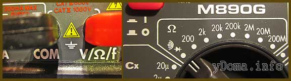
You can determine the value of the resistor using a multimeter included in the resistance measurement mode. In the sector of the resistance measurement mode, there are several switch positions. This is done in order to improve the accuracy of the measurement results. For example, position 200 allows you to measure resistances up to 200 ohms. 2k - up to 2000 Ohm (up to 2 kOhm). 2M - up to 2000000 Ohm. (up to 2 MΩ). The letter k after the numbers indicates the prefix kilo - the need to multiply the number by 1000, M stands for Mega, and the number must be multiplied by 1,000,000. If the switch is set to 2k, then when measuring a 300 kΩ resistor, the device will show an overload. It is necessary to switch it to position 2M. In contrast to measuring voltage, it does not matter what position the switch is in, you can always switch it during the measurement process.
Online calculators for determining the value of resistors
by color coding
Sometimes when checking a resistor, an ohmmeter shows some kind of resistance, but if the resistor has changed its resistance as a result of overloads and it no longer matches the marking, then such a resistor should not be used. Modern resistors are marked with colored rings. It is most convenient to determine the value of a resistor marked with colored rings using an online calculator.
marked with 4 colored rings
Online calculator for determining the resistance of resistors
marked with 5 colored rings
By appearance diodes come in various shapes, transparent and colored, in a metal, glass or plastic case. But they always have two conclusions and immediately catch the eye. The circuits mainly use rectifier diodes, zener diodes and LEDs. 
The symbol for diodes in the diagram is an arrow resting on a straight line segment. The diode is denoted by the Latin letters VD, with the exception of LEDs, which are denoted by the letters HL. Depending on the purpose of the diodes, additional elements are introduced into the designation scheme, which is reflected in the drawing above. Since there is more than one diode in the circuit, for convenience, a serial number is added after the letters VD or HL.
Testing a diode is much easier if you understand how it works. And the diode works like a nipple. When you inflate a ball, a rubber boat or a car wheel, the air enters them, but the nipple does not let it back out. The diode works the same way. Only passes in one direction not air, but electricity. Therefore, to test the diode, you need a constant current source, which can be a multimeter or a pointer tester, since they have a battery installed.
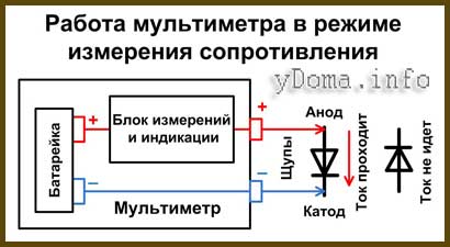
Above is a block diagram of a multimeter or tester in resistance measurement mode. As you can see, a DC voltage of a certain polarity is applied to the terminals. Plus is usually applied to the red terminal, and minus to the black. When you touch the diode terminals in such a way that the positive output of the device is at the anode terminal of the diode, and the negative output is at the cathode of the diode, then the current will flow through the diode. If the probes are interchanged, then the diode will not pass current.
The diode can usually have three states - to be serviceable, broken or open. Upon breakdown, the diode turns into a piece of wire, it will pass current in any order the probes are touched. With a break, on the contrary, the current will never flow. Rarely, but there is another condition when the transition resistance changes. Such a malfunction can be identified from the indications on the display.
According to the above instructions, you can check rectifier diodes, zener diodes, Schottky diodes and LEDs, both with leads and in SMD versions. Consider how to test diodes in practice.
First of all, it is necessary, observing the color marking, to insert the probes into the multimeter. Usually, a black wire is inserted into COM, and a red wire is inserted into V / R / f (this is the positive terminal of the battery). Next, you need to set the operation mode switch to the dialing position (if there is such a measurement function), as in the photo or to the 2kOm position. Turn on the device, close the ends of the probes and make sure that it works.

Let's start the practice by checking the ancient germanium diode D7, this instance is already 53 years old. Diodes based on germanium are now practically not produced due to the high cost of germanium itself and the low limiting operating temperature, only 80-100 ° C. But these diodes have the smallest voltage drop and self-noise level. They are very much appreciated by assemblers of tube sound amplifiers. In direct connection, the voltage drop across the germanium diode is only 0.129 mV. The dial gauge will show approximately 130 ohms. When changing the polarity, the multimeter shows 1, the dial tester shows infinity, which means a very large resistance. This diode is correct.
The procedure for testing silicon diodes is no different from testing those made of germanium. On the body of the diode, as a rule, the cathode terminal is marked, it can be a circle, a line or a dot. In direct connection, the drop at the diode junction is about 0.5 V. For powerful diodes, the drop voltage is less, and is about 0.4 V. Zener diodes and Schottky diodes are checked in the same way. The voltage drop of Schottky diodes is about 0.2 V.
For powerful LEDs, more than 2 V drops on the direct transition and the device can show 1. But here the LED itself is a health indicator. If even the faintest glow of the LED is visible during direct connection, then it is working. It should be noted that some types of powerful LEDs consist of a chain of several individual LEDs connected in series and this is not visible externally. Such LEDs sometimes have a voltage drop of up to 30 V, and it is possible to check them only from a power supply with an output voltage of more than 30 V and a current limiting resistor connected in series with the LED.
Checking electrolytic capacitors
There are two main types of capacitors, simple and electrolytic. Simple capacitors can be included in the circuit as you like, and electrolytic ones only with polarity, otherwise the capacitor will fail.

In electrical diagrams, a capacitor is represented by two parallel lines. When designating an electrolytic capacitor, its polarity of connection is necessarily indicated with a “+” sign.
Electrolytic capacitors are of low reliability, and are the most common cause of electronic component failure in products. A swollen capacitor in the power supply of a computer or other device is not a rare sight.
With a tester or multimeter in resistance measurement mode, you can successfully check the health of electrolytic capacitors, or, as they say, ring. The capacitor must be unsoldered from the printed circuit board and must be discharged so as not to damage the device. To do this, you need to short-circuit its conclusions with a metal object, such as tweezers. To check the capacitor, the switch on the device must be set to the resistance measurement mode in the range of hundreds of kilo-ohms or mega-ohms.

Next, you need to touch the probes to the terminals of the capacitor. At the moment of contact, the arrow of the device should deviate sharply along the scale and slowly return to the position of infinite resistance. The rate of deflection of the arrow depends on the value of the capacitance of the capacitor. The larger the capacitance of the capacitor, the slower the arrow will return to its place. A digital device (multimeter), when the probes touch the terminals of the capacitor, will first show a small resistance, and then increasing up to hundreds of megohms.
If the behavior of the devices differs from that described above, for example, the resistance of the capacitor is zero ohms or infinity, then in the first case there is a breakdown between the capacitor windings, and in the second, a break. Such a capacitor is defective and cannot be used.


