The scheme of LCD TV inverters for powering LEDs. If you want to repair such a device yourself, then you need to understand that you will need some knowledge and skills. If there is no experience, then it is better to call the master. Light bulbs do not turn on or
TDK inverter
This inverter (its schematic diagram is shown in Fig. 5) is used in 17-inch ACER, ROVER SCAN monitors with SAMSUNG matrices, and its simplified version (Fig. 6) is used in 15-inch LG monitors with an LG-PHILIPS matrix. The circuit is implemented on the basis of a 2-channel PWM controller from the company OZ960 O2MICRO with 4 outputs of control signals. As power switches, transistor assemblies of the FDS4435 type (two field-effect transistors with a p-channel) and FDS4410 (two field-effect transistors with an n-channel) are used. The circuit allows you to connect 4 lamps, which provides increased brightness of the LCD panel backlight.
The inverter has the following features:
- supply voltage - 12 V;
- rated current in the load of each channel - 8 mA;
- lamp operating voltage - 850 V, start voltage - 1300 V;
- output voltage frequency - from 30 kHz (at minimum brightness) to 60 kHz (at maximum brightness).
The maximum screen brightness with this inverter is 350 cd/m2;
- protection operation time — 1…2 s.
When the monitor is turned on, +12 V voltage is supplied to the inverter connector - to power the Q904-Q908 switches and +6 V - to power the U901 controller (in the version for the LG monitor, this voltage is formed from +12 V voltage, see the diagram in Fig. 6) . The inverter is in standby mode. The turn-on voltage of the ENV controller is supplied to the pin. 3 chips from the microcontroller of the main monitor board. The PWM controller has two identical outputs for powering two inverter channels: pin. 11, 12 and vyv. 19, 20 (Fig. 5 and 6). The frequency of the generator and PWM are determined by the values of the resistor R908 and capacitor C912 connected to the pin. 17 and 18 microcircuits (Fig. 5). Resistor divider R908 R909 determines the initial threshold of the sawtooth voltage generator (0.3 V). On the capacitor C906 (pin 7 U901), the threshold voltage of the comparator and the protection circuit is formed, the response time of which is determined by the value of the capacitor C902 (pin 1). The protection voltage against short circuit and overload (when the backlight breaks) is supplied to the pin. 2 chips. The U901 controller has a built-in soft start circuit and an internal regulator. The launch of the soft start circuit is determined by the voltage at the pin. 4 (5V) controllers.
Voltage transformer direct current in the high-voltage supply voltage of the lamps, it is made on two pairs of p-type FDS4435 and n-type FDS4410 transistor assemblies and is forcedly triggered by PWM pulses. A pulsating current flows in the primary winding of the transformer, and on the secondary windings of T901, the supply voltage of the backlight lamps connected to the connectors J904-J906 appears. To stabilize the output voltages of the inverter, the feedback voltage is fed through the full-wave rectifiers Q911-Q914 and the integrating circuit R938 C907 C908 and is fed to the pin in the form of sawtooth pulses. 9 controller U901. When one of the backlight lamps breaks, the current increases through the divider R930 R932 or R931 R933, and then the rectified voltage is supplied to the pin. 2 controllers exceeding the set threshold. Thus, the formation of PWM pulses on the pin. 11, 12 and 19, 20 U901 is blocked. In the event of a short circuit in the circuits C933 C934 T901 (winding 5-4) and C930 C931 T901 (winding 1-8), voltage spikes occur, which are rectified by Q907-Q910 and also fed to the pin. 2 controllers - in this case, the protection is activated and the inverter turns off. If the short circuit time does not exceed the charge time of the capacitor C902, the inverter continues to operate normally.
The fundamental difference between the circuits in Fig. 5 and 6 in that in the first case more complex scheme soft start (the signal is sent to pin 4 of the microcircuit) on transistors Q902, Q903. In the diagram in fig. 6, it is implemented on the capacitor C10. It also uses assemblies of field-effect transistors U2, U3 (p- and n-type), which simplifies their power matching and ensures high reliability in circuits with two lamps. In the diagram in fig. 5, field-effect transistors Q904-Q907 are used, connected in a bridge circuit, which increases the output power of the circuit and the reliability of operation in start-up modes and at high currents.
Inverter Faults and Solutions
Lamps do not turn on
Check the presence of supply voltage +12 and +6 V on pin. Vinv, Vdd inverter connector respectively (Fig. 5). In their absence, check the health of the main monitor board, assemblies Q904, Q905, zener diodes Q903-Q906 and capacitor C901.
Check the supply of +5 V inverter turn-on voltage to pin. Ven when putting the monitor into working mode. You can check the health of the inverter using an external power source by applying a voltage of 5 V to the pin. 3 U901 chips. If the lamps turn on at the same time, then the cause of the malfunction is in the main board. Otherwise, the elements of the inverter are checked, and the presence of PWM signals on the pin is monitored. 11, 12 and 19, 20 U901 and, in their absence, replace this chip. They also check the health of the windings of the T901 transformer for an open and short circuit of the turns. When a short circuit is detected in the secondary circuits of the transformer, the serviceability of the capacitors C931, C930, C933 and C934 is first checked. If these capacitors are in good condition (you can simply unsolder them from the circuit), and a short circuit occurs, open the place where the lamps are installed and check their contacts. Burnt contacts are repaired.
The backlights flash for a short time and immediately go out
Check the serviceability of all lamps, as well as their connection circuits with connectors J903-J906. You can check the health of this circuit without disassembling the lamp unit. To do this, the feedback circuits are turned off for a short time, sequentially soldering the diodes D911, D913. If at the same time the second pair of lamps turns on, then one of the lamps of the first pair is faulty. Otherwise, the PWM controller is faulty or all lamps are damaged. You can also check the inverter’s performance by using an equivalent load instead of lamps - a 100 kΩ resistor connected between the cont. 1, 2 connectors J903, J906. If in this case the inverter does not work and there are no PWM pulses on the pin. 19, 20 and 11, 12 U901, then check the voltage level at the pin. 9 and 10 microcircuits (1.24 and 1.33 V, respectively. In the absence of the indicated voltages, the elements C907, C908, D901 and R910 are checked. Before replacing the controller microcircuit, the rating and serviceability of the capacitors C902, C904 and C906 are checked.
Inverter turns off spontaneously after a while (a few seconds to a few minutes)
Check the voltage at the output. 1 (about 0 V) and 2 (0.85 V) U901 in operating mode, if necessary, change the capacitor C902. With a significant difference in the voltage at the pin. 2 from the nominal value, check the elements in the short circuit and overload protection circuit (D907-D910, C930-C935, R930-R933) and, if they are in good condition, replace the controller chip. Check the voltage ratio on the pin. 9 and 10 microcircuits: on pin. 9 voltage should be lower. If this is not the case, check the capacitive divider C907 C908 and the feedback elements D911-D914, R938.
Most often, the cause of such a malfunction is caused by a defect in the capacitor C902.
The inverter is unstable, there is a flashing of the backlight lamps
Check the performance of the inverter in all modes of operation of the monitor and in the entire range of brightness. If instability is observed only in some modes, then the main monitor board (brightness voltage generation circuit) is faulty. As in the previous case, an equivalent load is included and a milliammeter is installed in the circuit break. If the current is stable and equal to 7.5 mA (at minimum brightness) and 8.5 mA (at maximum brightness), then the backlight lamps are faulty and must be replaced. Also check items secondary circuit: T901, S930-S934. Then check the stability of rectangular pulses (average frequency - 45 kHz) on the pin. 11, 12 and 19, 20 U901 chips. The DC component on them should be 2.7 V at the P-outputs and 2.5 V at the N-outputs). Check the stability of the sawtooth voltage at the pin. 17 chips and, if necessary, replace C912, R908.
SAMPO inverter
Schematic diagram of the SAMPO inverter is shown in fig. 7. It is used in 17-inch SAMSUNG, AOC monitors with SANYO matrices, monitors "Proview SH 770" and "MAG HD772". There are several modifications to this scheme. inverter forms output voltage 810 V at rated current through each of the four fluorescent lamps (about 6.8 mA). The starting output voltage of the circuit is 1750 V. The frequency of the converter at an average brightness is 57 kHz, while the brightness of the monitor screen is up to 300 cd/m2. The response time of the inverter protection circuit is from 0.4 to 1 s.
The basis of the inverter is the TL1451AC chip (analogues - TI1451, BA9741). The microcircuit has two control channels, which allows you to implement a power supply circuit for four lamps. When the monitor is turned on, +12 V voltage is supplied to the inputs of +12 V voltage converters (sources of field-effect transistors Q203, Q204). The dimming voltage DIM is supplied to the pin. 4 and 13 microcircuits (inverted inputs of error amplifiers). When a turn-on voltage of 3 V (pin ON / OFF) is received from the main board of the monitor, transistors Q201 and Q202 open and on the pin. 9 (VCC) of the U201 chip, +12 V is supplied. 7 and 10, rectangular PWM pulses appear, which go to the bases of transistors Q205, Q207 (Q206, Q208), and from them to Q203 (Q204). As a result, voltages appear on the right terminals of the inductors L201 and L202 according to the scheme, the value of which depends on the duty cycle of the PWM signals. These voltages feed the oscillator circuits made on transistors Q209, Q210 (Q211, Q212). On the primary windings 2-5 of the transformers RT201 and RT202, respectively, a pulsed voltage appears, the frequency of which is determined by the capacitance of the capacitors C213, C214, the inductance of the windings 2-5 of the transformers RT201, RT202, as well as the level of the supply voltage. When adjusting the brightness, the voltage at the outputs of the converters changes and, as a result, the frequency of the generators. The amplitude of the output pulses of the inverter is determined by the supply voltage and the state of the load.
Autogenerators are made according to a half-bridge circuit, which provides protection against high currents in the load and a break in the secondary circuit (turning off lamps, breakage of capacitors C215-C218). The heart of the protection circuit is in the U201 controller. In addition, the protection circuit includes elements D203, R220, R222 (D204, R221, R223), as well as a feedback circuit D205 D207 R240 C221 (D206 D208 R241 C222). When the voltage at the output of the converter rises, the zener diode D203 (D204) breaks through and the voltage from the divider R220, R222 (R221, R223) is fed to the input of the overload protection circuit of the controller U201 (pin 6 and 11), increasing the protection threshold for the time the lamps start. Feedback circuits rectify the voltage at the output of the lamps and it goes to the direct inputs of the controller error amplifiers (pin 3, 13), where it is compared with the dimming voltage. As a result, the frequency of the PWM pulses changes and the brightness of the lamps is maintained at a constant level. If this voltage exceeds 1.6 V, then the short circuit protection circuit will start, which will work during the charge of the capacitor C207 (about 1 s). If the short circuit lasts less than this time, the inverter will continue to operate normally.
SAMPO Inverter Faults and Solutions
The inverter does not turn on, the lamps do not light up
Check the presence of +12 V voltages and the active state of the ON / OFF signal. In the absence of +12 V, check its presence on the main board, as well as the serviceability of transistors Q201, Q202, Q205, Q207, Q206, Q208) and Q203, Q204. If there is no ONN / OFF inverter turn-on voltage, it is supplied from an external source: + 3 ... 5V through a 1 kΩ resistor to the base of transistor Q201. If the lamps turn on at the same time, then the malfunction is related to the formation of the inverter turn-on voltage on the main board. Otherwise, check the voltage at the pin. 7 and 10 U201. It should be equal to 3.8V. If the voltage at these pins is 12V, then the U201 controller is faulty and must be replaced. Check the reference voltage at the pin. 16 U201 (2.5 V). If it is zero, check the capacitors C206, C205 and, if they are working, replace the controller U201.
Check the presence of generation on the output. 1 (sawtooth voltage swing 1 V) and, in its absence, capacitor C208 and resistor R204.
Lights come on but then go out immediately (within less than 1 second)
Check the health of the zener diodes D201, D202 and transistors Q209, Q210 (Q211, Q212). In this case, one of the pairs of transistors may be faulty. They check the overload protection circuit and the health of the zener diodes D203, D204, as well as the values of resistors R220, R222 (R221, R223) and capacitors C205, C206. Check the voltage at the output. 6 (11) controller chips (2.3 V). If it is underestimated or equal to zero, check the elements C205, R222 (C206, R223). In the absence of PWM signals on the pin. 7 and 10 U201 microcircuits measure the voltage at the pin. 3 (14). It should be 0.1 ... 0.2V more than the pin. 4 (13), or the same. If this condition is not met, check the elements D206, D208, R241. When carrying out the above measurements, it is better to use an oscilloscope. Turning off the inverter may be due to a break or mechanical damage to one of the lamps. To test this assumption (in order not to disassemble the lamp assembly), the + 12V voltage of one of the channels is turned off. If at the same time the monitor screen starts to glow, then the disabled channel is faulty. They also check the serviceability of transformers RT201, RT202 and capacitors C215-C218.
The lamps spontaneously turn off after a while (from units of seconds to minutes)
As in previous cases, they check the elements of the protection circuit: capacitors C205, C206, resistors R222, R223, as well as the voltage level at the pin. 6 and 11 of the U201 chip. In most cases, the cause of the defect is caused by a malfunction of the capacitor C207 (which determines the protection response time) or the controller U201. Measure the voltage at the inductors L201, L202. If the voltage rises steadily during the operating cycle, check transistors Q209, Q210 (Q211, Q212), capacitors C213, C214 and zener diodes D203, D204.
The screen flickers intermittently and the brightness of the screen backlight is unstable
Check the health of the feedback circuit and the operation of the controller error amplifier U201. Measure the voltage at the output. 3, 4, 12, 13 chips. If the voltage at these terminals is below 0.7V, and at the pin. 16 below 2.5V, then replace the controller. Check the health of the elements in the feedback circuit: diodes D205, D207 and D206, D208. Connect load resistors with a nominal value of 120 kΩ to the CON201-CON204 connectors, check the level and stability of the voltages on the pin. 14 (13), 3 (4), 6 (11). If the inverter operates stably with the load resistors connected, replace the backlight lamps.
Currently, almost every apartment has personal computers, system units, or laptops. Laptops are a separate difficult topic, they need regular qualified care, prevention, timely replacement of thermal paste, lubrication of coolers with silicone grease, otherwise the chipset will fall off over time. motherboard laptop.
With system units, everything is much simpler, there the conditions for cooling semiconductor radio components that do not like prolonged overheating are much better. But along with system units, LCD and LED monitors are used to display visual information. If with the latest, LED monitors, there are usually no problems, since they have neither inverters nor CCFL matrix backlight lamps, reminiscent of appearance conventional fluorescent lamps. Then with LCD monitors after 6-7 years of operation problems often arise.

Which, by the way, home craftsmen check CCFL backlight lamps by connecting to, which are nothing more than ordinary fluorescent lamps with a glass bulb twisted into a spiral and a low-power electronic ballast built into the lamp base. CCFL lamps require high voltage, which we get using step-up transformers installed in the monitor inverter.

LCD monitor inverter
Often the number of transformers is equal to the number of lamps, but there are also options for transformers with twice the number of windings, for two lamps at once. What most often breaks in LCD monitor inverters?
First. I think that loved by all masters for the ease of repair - in the line filter of 13 volts of the power supply. By the way, electrolytic capacitors with an operating voltage of not 16 volts are installed in this line, as novice masters might think, since the operating voltage of electrolytic capacitors must exceed the supply voltage in the circuits in which they are located. No, 25 volt capacitors are installed there, and in LCD TVs and monitors with a larger diagonal, it happens that there are also 35 volt capacitors due to the fact that the operating voltage there is not 13 volts, but higher. So, why are capacitors still installed at 25 volts, and not at 16 V?
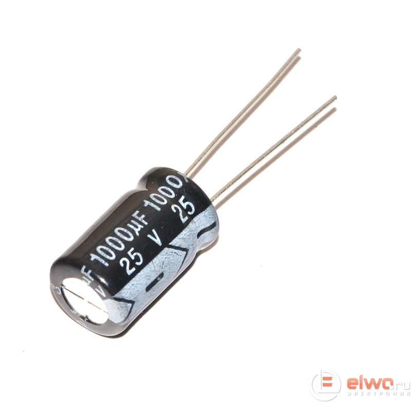
Capacitor 1000x25v
The fact is that when the inverter is operating in abnormal mode, the output circuits of the power supply for 13 volts are not loaded, there is a voltage of about 18 volts at the output, and under load, when the inverter is operating in normal mode, it sags to the standard 13 volts. By the way, if you have an LED blinking at the same frequency on a non-working LCD monitor, this is already a sign that everything is fine with the LCD monitor control board, the scaler, since there is an error indication, and there are already problems in the inverter circuits.

If there is no reaction at all to pressing the power button, you need to check the 5 volt power circuits, in particular the electrolytic capacitors on the power supply board, for 10 volts. On the connector of the power supply connected by a cable to the scaler, in addition to the 5 volts necessary for the operation of the scaler, there are also 13 volts. Sometimes, an additional 3.3 volts from a low-power SMD stabilizer come from the power supply board to the scaler. All these voltages on the connector can be found out by first determining its pinout according to the inscriptions, silk-screen printed on the board, or by downloading the Service manual for this monitor.

Be careful when measuring the voltage at the connector of the monitor that is on, it is best to take ordinary pins, clamp them (if you have any of course) into multimeter probes, with crocodile clips at the ends. Thus, by sticking the pins into the contacts of the crimped wire, the cable on the connector, you will be able to take measurements on the power connector and not short anything on the board. So, you measured, you see that you don’t have one voltage, for example 13 volts. What can it say?

We measure the voltage with a multimeter
You may have a short circuit, a short circuit in the 13 volt circuits. You can make sure that this is not the case by touching the probes of the multimeter, in the sound continuity mode, of course, when the voltage is removed from the monitor, unplugged from the outlet, on the power connector, contacts signed + 13V and GND. If your measurement resistance is close to zero or even tens of ohms, this means that the assemblies of mosfets in the inverter, field-effect transistors, they are also called “keys”, are broken, and most likely short-circuited, the 13 volt power input to ground.
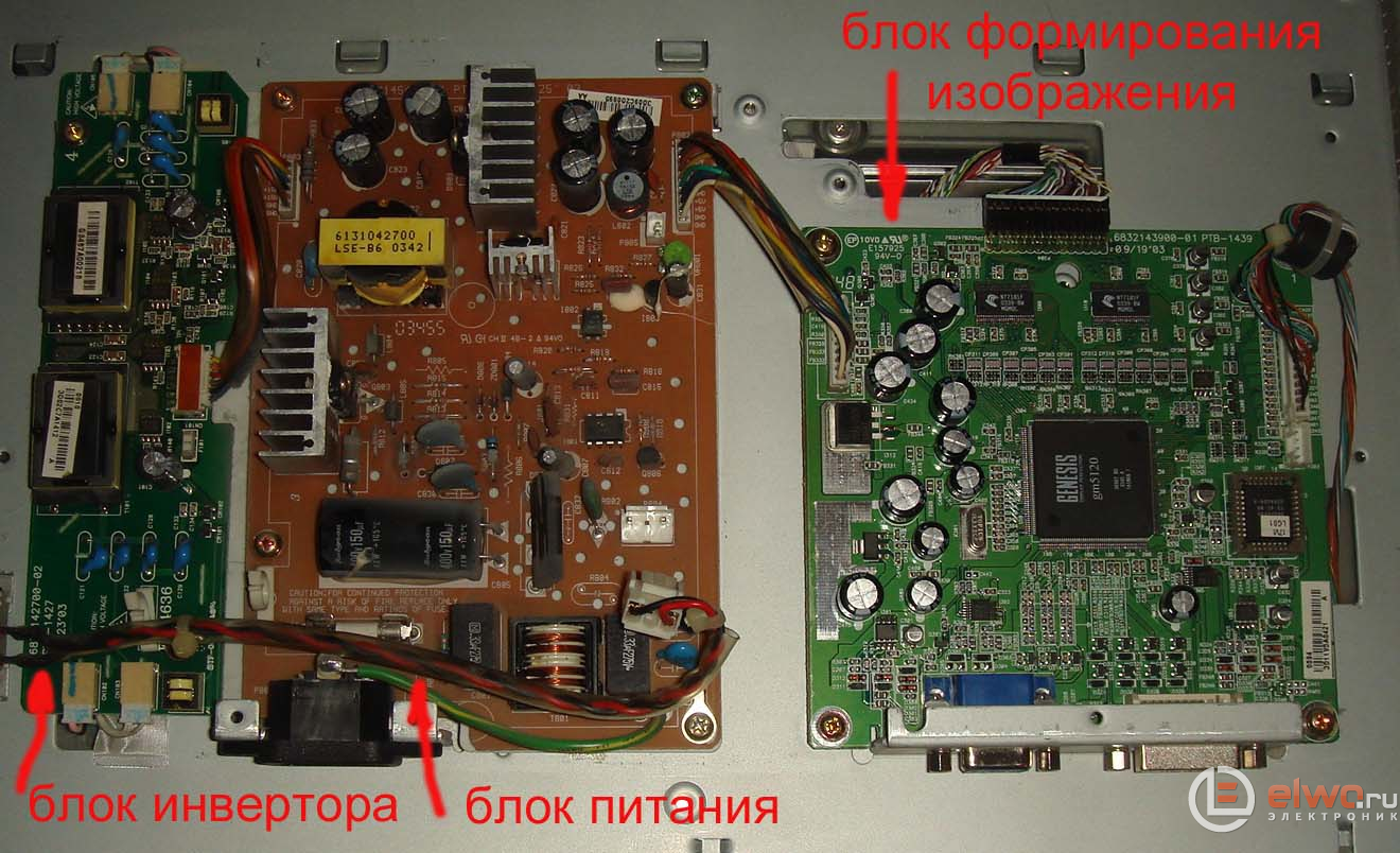
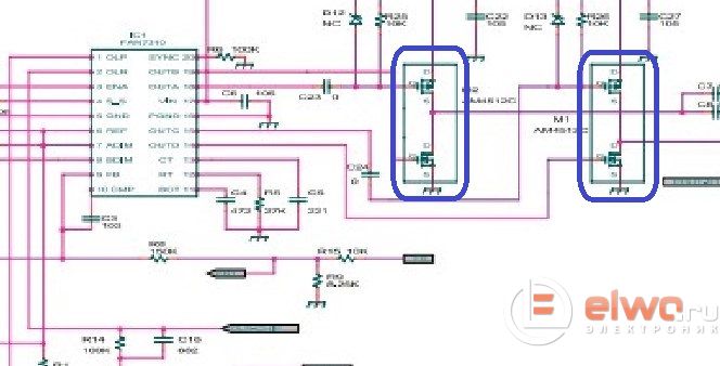
Three boards from the monitor scaler power supply and inverter
But even if during the measurement we did not detect a 13 volt short circuit on the power connector, we still need to ring the key mosfet assemblies. These assemblies include two transistors, p and n channel, the outputs of which are short-circuited on the board. These are usually the conclusions of the assemblies that go most often in the SO-8 package, numbered 5,6,7,8. The sources of transistors, and these are usually legs 1 and 3, are paralleled among themselves for both assemblies of mosfets.

How, then, to determine which of the mosfet assemblies is broken, because the punched conclusions of one assembly connected in parallel will shunt the conclusions of the second assembly with their low resistance? If you really want to identify which of the assemblies burned out, you can solder special wires on the board, jumpers, and parallelize the assembly outputs. But usually this is not necessary. Why? - I'll explain now.
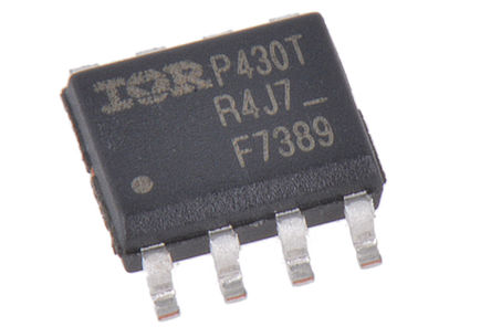
IRF7389 photo
The fact is that when mosfets change, the upper shoulder or the lower, in other words, a mosfet that has a connection either to ground or to the plus of the power supply, especially if polyphase power is used according to the circuit design, mosfets or mosfet assemblies should be changed STRICTLY to the original or as a last resort to an absolutely complete analogue. If there is no desire to delve into datasheets for a long time, comparing the parameters of analogues and at the risk that the analogue will still not work and subsequently burn out, you should change, in the case of monitor inverters, both assemblies of mosfets at once, always with the same ones.
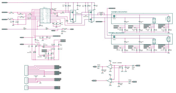
Click on diagram to enlarge
And since finding the original part used is problematic in our radio stores, but there is a well-proven, relatively inexpensive, common analogue, at a price of only 45 rubles, IRF7389, I always do this, I change both assemblies at once, both keys. And here we are approaching the most interesting. How can I change these octopuses in an SMD case at home? Without experience, if you change them for the first time, there is a risk of getting torn off thin roads on the board.

Drains of transistors are usually on one side of the microcircuit, our assembly, they are connected to each other, and even if you tore off the contact on the board, no one bothers you to thoroughly smear the board and the remaining contacts with flux, fill them with molten solder.
This is even recommended, since the more you fill the leads with solder, the less the board, tracks, from poor contact, etc., etc. will heat up. And the currents there, at the output, are rather big. So, how can we dismantle the chip?
First. If you have a soldering iron, this procedure is easy and simple. We apply the Rose or Wood alloy, the latter is preferable, since it has a lower melting point compared to the Rose alloy, less than 100 degrees.
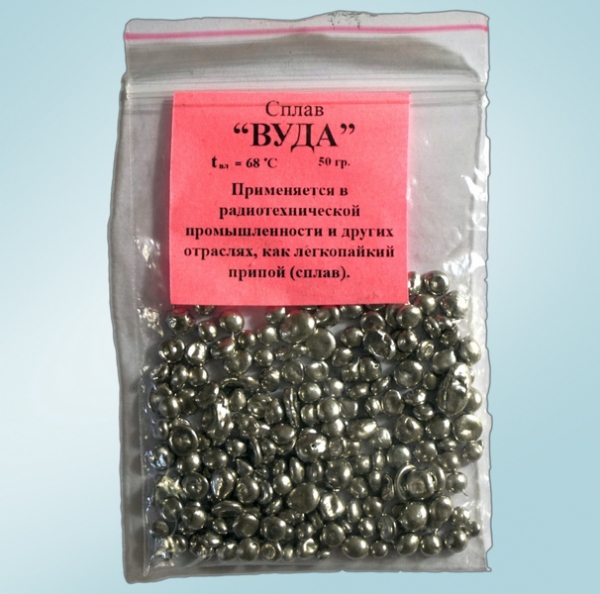
Alloy wood photo
We bit off a piece from a drop of Wood's solder with side cutters, put it on the contacts of the microcircuit. The droplet should not be small and not very large. We melt it with a soldering iron and distribute it among the contacts so that all the leads, on both sides, are closed with this solder. Of course, pre-apply abundant flux on all contacts. Having had the RMA-223 flux for a long time, out of habit I use only alcohol-rosin flux prepared by myself - the soldering quality is beyond praise.

646 solvent photo
And it is removed from the board using 646 solvent after soldering easily and quickly, there is practically no dirt left and the board dries instantly, due to the high volatility of the solvent. No corrosion of contacts and similar problems were noticed in the future. Do not buy ready-made alcohol-rosin flux in radio stores, always make it yourself. There was a negative experience of buying such a flux, in which rosin was diluted by the manufacturer instead of alcohol with some kind of filth, which even 646 solvent did not take, and after soldering the capacitors on the motherboard, I had to give, blushing, a sticky board to a familiar computer hardware dealer, I have it and now there is a full tube.

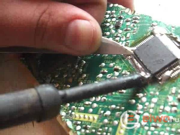
Dismantling with a blow dryer
So, we applied and distributed Wood's alloy over all contacts, then we heat the microcircuit with a hairdryer on average temperature, constantly gently rocking the chip from side to side. Why are we doing this? The fact is that the manufacturer, for some reason incomprehensible to us, is not enough that the microcircuit is soldered almost tightly on the board, and during the production of electronics on production lines, he applies one, and in especially severe cases, even two drops under the microcircuit case glue.

And until this glue softens from soldering temperature, you will not be able to remove the chip from the inverter board.
Second method, which I use when making repairs outside the home, in the absence of access to a blow dryer. In the same way, we apply Wood's alloy to the contacts of the microcircuit and, holding the microcircuit with tweezers on both sides, where it has no contacts, the tweezers must be notched on the lips so that they do not slip off during dismantling.
We alternately heat the microcircuit contacts with a soldering iron tip, on both sides, quickly changing sides. The soldering iron must be domestic, EPSN with a power of 65 watts. I think it would never occur to anyone to use a soldering iron with a ceramic heater and a fireproof tip at this temperature, since overheating the tip there is fraught with the fact that it will darken and the solder will simply stop sticking to it.
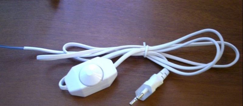
Dimmer on power cord
If it's possible to slightly lower the temperature of a 65 watt soldering iron with a dimmer - fine, no - try this. A 40 watt soldering iron is not enough for dismantling in this way. This method is only suitable if you are not going to re-solder the soldered microcircuit somewhere. Since in connection with high temperature soldering iron tips, the microcircuit, most likely, will already be discarded. But with the complete absence of access to a soldering dryer, as practice shows, this is a completely working option.

MGTF wire
The only thing is, if you didn’t manage to solder the microcircuit in this way during the warming up of the board within 30 seconds, ALWAYS take a break for 2 minutes, let the board cool down, otherwise it’s very likely that your textolite will rear up, and thin roads will have to be “thrown” by the MGTF canopy , to the pins on the board, or the pins of the elements connected by this track. And if SMD elements were soldered to these roads, then you will also have to solder everything after what happened.

Alcohol rosin flux photo
After three or four times, dismantling in this way, this procedure will be easy and fast. So, we dismantled the microcircuit, in the first or second way, it doesn't matter. Now we need to align the contact pads on the board, from the solder bumps that have arisen. To do this, we take a soldering iron with a power of 25-40 watts, a dismantling braid, and again we apply abundant alcohol-rosin flux to the contacts.

Dismantling oletka
The tip of the braid, for better absorbency, can even be dipped in flux. After removing the “snot” from the board, we get ready-made sites for mounting a new microcircuit. Installation can be done in two ways. We apply, quite a bit, the usual POS-61 lead-containing solder to the contacts on the board, but so that the pads remain straight. This solder has a lower melting point than lead-free solder used by the electronics manufacturer.
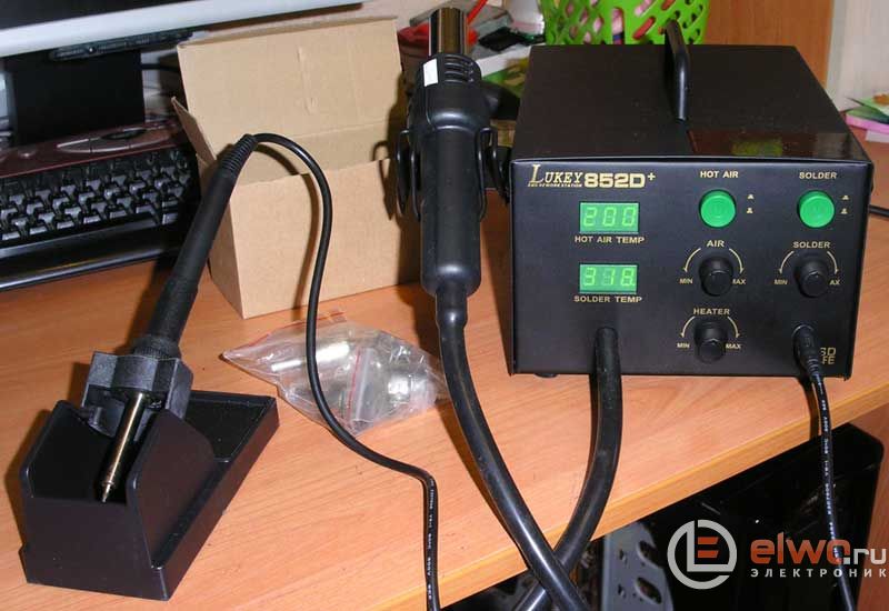
Soldering station photo
Then we put our chip on the board, positioning it so that the pins match the pins exactly. You can also smear the legs of the microcircuit with alcohol-rosin flux. Then it is soldered instantly and at a low temperature of the hair dryer. The temperature itself, set the average on the soldering iron, the air flow is also moderate, otherwise the microcircuit will be blown away, it may solder a little crookedly, and you will have to dismantle it and solder it on a new one.
Second way mounting of the microcircuit is carried out without a soldering dryer, using a conventional soldering iron with a power of 25 watts, with a thin, sharply sharpened tip. Also, as it was written above, we apply the flux, and with a light touch, picking up quite a bit of solder, on the soldering iron tip, we touch the two legs of the microcircuit, and the contacts on the board located diagonally. Thus, we grab the microcircuit, and we already have it, it will not go anywhere.
Dismantling the SMD chip
Then calmly solder all the remaining legs in the same way. On the legs of the microcircuit 5-8 connected on the board, we apply more solder in order to reduce the heating of the board in this place. Then we call, just in case, with a multimeter in the sound continuity mode, adjacent contacts for a short circuit relative to each other, or we look at the contacts under a good 10-20x magnifying glass for the same purpose.

Flux off
And then we wash off all the dirt and traces of flux 646 with a solvent, or with a special tool for washing FluxOff boards, let the board dry, make sure that the circuit is gone, assemble the monitor, turn it on and enjoy its work.
Finally
Someone who has no experience in such repairs will say that everything is too complicated, I probably can't handle it. In fact, such repairs can be made much faster than I spent the time writing this article, a description of all the nuances of the repair. And as practice shows, in a crisis, people with such knowledge become even more in demand and, in addition to the savings received, if completed, they can always get an additional side job by repairing electronics on the side - to all their friends. We wish you successful repairs! AKV.
Got on the occasion monitor Samsung 940N. When turned on, an image appeared for a second, then the screen went blank. During verification, the backlight transformer was found to be faulty (breakage of one secondary winding). There was no new transformer, and its replacement in workshop conditions was slightly less than the cost of the monitor. It was decided to try to restore it at home.
The transformer was soldered out of the monitor board, inspected. Its design was not subject to disassembly. Since the backlight converter was single-ended (there is most likely a gap in the transformer core), it was decided to break it carefully in order to try to restore it in the future (gluing gaps should not greatly impair its operation).
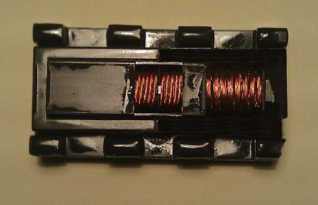
With a screwdriver, its side jumpers were carefully broken off from the W-shaped core. Then, to free access to the winding, the plastic frame of the transformer.
The old winding was cut off and a new winding was wound in its place, 8 sections of 80-100 turns in one section with a thin wire (was 0.1), preferably even thinner is needed.
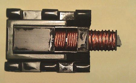
After winding the winding, the transformer core was glued with super glue. The glued seam is clearly visible in the photo. The frame of the transformer was also glued together. It turned out without the upper protective part (the pieces were too small).

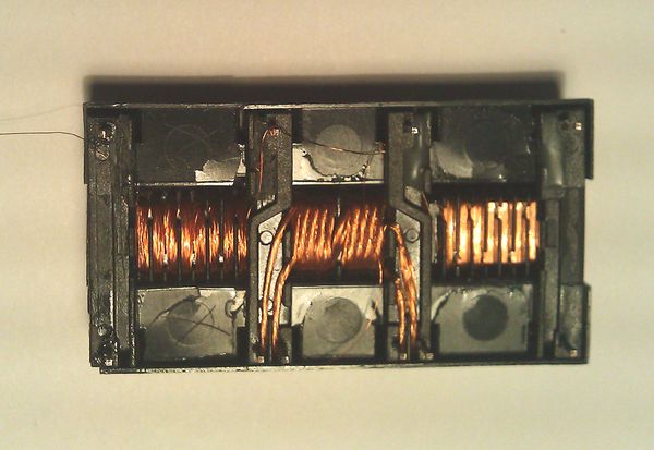
Below in the figure is a view of the transformer from the back side, a new winding on the left side, the conclusions have not yet been soldered. After soldering the leads and continuity of the transformer, the resistance of the new winding turned out to be much lower than the remaining one. Well, this is understandable, the new winding was wound with a thicker wire than the original one.
Next, the transformer was installed in the monitor power supply board (new winding on the bottom side of the board). The monitor was assembled and tested for performance.
After the monitor was turned on, all the backlights lit up, the power supply did not go into protection. A test run of the monitor showed quite satisfactory operation of the repaired transformer.
It is also possible to restore the monitor's performance without rewinding the transformer - by transferring the monitor to work only from 2 backlight lamps (one on top and one on the bottom), which can be powered from the remaining working secondary winding of the high-voltage transformer. To do this, it will be necessary to remove the CA2 SMD diode from the monitor power supply board: D10 or D11, (depending on which transformer winding is faulty) and rearrange the backlight connectors accordingly. The faulty winding will need to be mechanically, carefully removed (cut with a knife). After that, accordingly, the brightness of the monitor will decrease slightly, but the monitor will remain fully functional.
This article discusses the main points to consider when repairing inverters for LCD TVs and monitors.
LCD TV inverter repair.
If you want to repair such a device yourself, then you need to understand that you will need some knowledge and skills. If there is no experience, then it is better to call the master.
Television inverter is a device that is responsible for starting and uninterrupted operation of the backlight of any LCD panel. With it, you can easily increase or decrease the brightness of the image. Before you start troubleshooting a possible malfunction of this device, you need to understand what it does:
First of all, the device converts the voltage, which, as a rule, does not exceed 24 V, into high voltage.
The second responsibility is to regulate the supply in fluorescent lamps, as well as its stabilization.
As mentioned above, changing the brightness is also his direct responsibility.
One of the most useful functions is to protect the TV from all kinds of overloads, as well as to prevent short circuits.
Faults directly related to the inverter:
Light bulbs do not turn on or work intermittently.
Spontaneous change in screen brightness or flashing.
When the inverter refuses to work after a long period of inactivity, this is one of the most serious malfunctions.
Unequal backlighting of the screen in the presence of a circuit of 2 devices also refers to problems.
Troubleshooting:
If one of the above malfunctions is found, then first you need to check the voltage for the absence of ripples and stability.
Then you need to pay attention to the quality of the passage of commands related to turning on the lamps and adjusting the backlight. They come from the motherboard.
If the problem is still not found, you need to remove the protection from the inverter itself and start looking for a breakdown. Next, a careful inspection of the board for burnt elements follows.
After that, it does not hurt to measure indicators such as voltage and resistance with a tester.
Checking transistor keys is also worth paying attention to, they are often to blame.
This is followed by a check of high-voltage transformers. Incorrect assembly or poor insulation of these devices can also cause problems. Breaks and short circuits between individual turns can still occur on transformers. Such problems are also detected during inspection and verification of the device.
LCD monitor inverter repair.
Most computer monitors inevitably develop problems over time. And they are all the same for the most part.
Monitor problems :
Failure of the screen backlight due to broken lamps.
Turning on the lamps for a short period of time and then turning off.
Unstable monitor brightness, flickering.
Troubleshooting.
The first step is to check the voltage in the power system, normal rate more than 12 V. If it is not there at all, then you need to check the fuses. If the problem is here, then before replacing, you need to inspect the transistors.
In the case when the listed operations are useless, the microcircuit must be completely changed. Now you need to inspect the converter for disruption of generation. Checking transistors will also not be superfluous.
Next, the ENB signal should be tested. If not, then the problem must be sought in the main board. If there is a signal, then you need to inspect all the lamps and look for damage or burnt elements. If the problem still persists, then the secondary circuits should be checked further, so the protection that protects against short circuits can work. For the same purpose, you can inspect the transistor, divider, and zener diode. In a situation where the voltage at the terminals is less than 1 V, then a new capacitor must be installed.
This is followed by a study of the stability of the brightness voltage of the resistor, which must be disconnected from the feedback before testing. If the voltage is not stable, then the problem lies in the main monitor board. The next step is to check the oscillations and stability of the so-called sawtooth pulse generator. The amplitude should be in the range from 0.7 to 1.3 V. The frequency indicator should be in the region of 300 kHz. If the voltage is unstable, then the device must be changed.