Big encyclopedia of oil and gas. Supports. Support structures and their symbols
Students of the course "Calculation of building structures - from scratch!", Which I lead in the Dystlab Education project, periodically ask me to explain to them such concepts as "hinge", "hinge support". Apparently, the understanding of these important elements, from the point of view of the operation of the structure, causes some difficulties for novice designers.
Various dictionaries and wikis define a hinge as a "rotational kinematic pair", which terminologically refers more to mechanical engineering (elements of machines and mechanisms) than to building structures, although the principle of the hinge is the same everywhere. Hinge - a device that connects two elements in such a way that they can rotate about one point or axis.
Various schemes for using hinges are demonstrated in the following videos. In the first video, hinges are used for window and door systems, in the second - for camera gyro stabilization (not one, but several hinges are used):
Video 1. Hinge Examples
Video 2. Hinges as part of a complex mechanism
From these videos, the concept itself should become clear: the hinge is needed where it is not required to rigidly fix the element, but it is necessary to allow it to rotate.
Hinges in building structures
In buildings and structures, hinges are used, as a rule, in the most critical nodes - supports. Sometimes hinges are introduced into some "internal" part of the structure:
Bearing part of the span structure of the bridge

Rope fastening on temporary supports is also articulated

Hinge as part load-bearing structure in a civil building

Pedestrian bridge, implemented according to the "three-hinged arch" scheme (a rare design!)

Articulated support of the attraction "Ferris wheel"
Hinges in design schemes
One way or another, the design of a structure begins with the development of its design scheme. Consider a few examples of the simplest calculation schemes:

Figure 1. Examples of design schemes with hinged supports
Whether it surprises you or not, all three diagrams show the same type of structural support - hinged. Please note that the left support in each diagram is "rotated" by some angle. This was done only to emphasize that now we are working not with a real structure, but with its virtual counterpart, a simplified model (calculation scheme). And on calculation scheme it is important to note only those features that fundamentally affect the operation of the structure: in this case, these are two support rods with which the structure is attached to the ground.
Here is another example of a design scheme taken from the explanatory note of the 1905 overpass project:
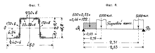
Figure 2. Articulated beam, project 1905
On the right (Fig. 8, Fig. 2) a simple beam on two supports is shown, and the black triangles show the articulated and articulated fixed support(although it’s hard to find out which one is which, but this is a question for the authors of the project, engineers E. O. Paton and P. Ya. Kamentsev). As you can see, the single correct variant in the notation articulated support no, and how to show this element on the diagrams is up to you.
What does the circle mean
As you can easily see, in the diagrams the hinge symbolizes a small circle. The support section of the structure rotates around this center:

Figure 3. Structure sections A, B rotate in bending around hinged supports
Movements and reactions
The hinge allows the section to rotate around its center. Since angular movements are allowed at this point, there is no corresponding reference moment. This is the main purpose of the hinge in the building structure - to zero the moments that appear in the process of bending:

Figure 4. Hard pinch (1) and articulated support(2) beams
What is the difference between movable and fixed supports?
You probably noticed that in Figures 1, 3, 4 the beams lie on different supports: on the left, the support is drawn with three circles a mi and two connecting lines, and on the right - two circles a mi and one line. Why is that?
Each connecting line (short segment in the image of the support) models the attachment of this node to the ground, so linear movements of the beam in this direction are prohibited. So, the beam cannot bend down in the supporting sections; both at the beginning and at the end of the structure, vertical or inclined rods are drawn to support the beam. Let me remind you that an inclined structure can always be projected onto mutually perpendicular axes (vertical and horizontal), so scheme 2 in Figure 1 is not fundamentally different from the others.
It is also important to understand the purpose of the single horizontal support bar. It prohibits the horizontal movement of the beam (in the direction of the longitudinal axis), but only of the section in which it is installed. This is a classic hinged-fixed support:

Figure 5. What movements are prohibited and permitted by hinged supports
In Figure 5, the right support is called articulated, as it allows the right end of the beam to move in the horizontal direction. This is an important circumstance for taking into account elongations and shortenings of the structure due, for example, to temperature fluctuations.
conclusions
The hinge is important element design: it allows the sections that are attached to it to rotate around the hinge axis. The hinge resets the reference moments.
On the design diagram, the hinge is shown, as a rule, in a circle. Hinged-movable and hinged-fixed supports are one of the most common types of support for beam systems. Both of them have hinges and allow rotation of the reference section, and the articulated support also allows horizontal movements of the corresponding end of the beam.
It is customary to say that the supports are attached "to the ground", but this should not be taken literally. Often, the "ground" is another structural element, of greater rigidity.
On fig. 1.21 shows a horizontal beam based on hinged and movable and fixed supports at points A and B.
Reaction R A of the pivotally movable support is directed normal to the supporting surface towards the beam. The articulated movable support is placed on rollers, which do not prevent the beam from moving along the supporting surface. If we do not take into account the friction of the rollers, then the line of action of the reaction R A passes through the hinge center perpendicular to the bearing surface.
The hinged-fixed support prevents translational movements of the beam along the coordinate axes, but allows it to rotate about the hinge axis. Reaction action line R B of the hinged support passes through the center of the hinge, but the modulus and the direction of the reaction are not known in advance.
On fig. 1.22 shows the beam AB. According to the axiom of the parallelogram of forces, which allows the reverse interpretation, the reaction R B can be decomposed into components parallel to the coordinate axes.
FROM

More complex types of connections and their reactions are considered later, when the concepts are introduced. pairs of forces and moments of forces about a point and an axis.
Axiom of connections - any non-free body can be considered as free, if we discard the bonds and replace their action with the reactions of these bonds.
On fig. 1.23 shows the beam AB, considered as a non-free mechanical system, on which external constraints are imposed.
The hinged fixed support at point B does not allow the beam to move translationally parallel to the coordinate axes and allows it to rotate in the plane of the figure. Based on this, the reaction R B is decomposed into its components Y AT, Z B, parallel to the coordinate axes.
The hinged-movable support at point A does not allow the beam to move to the supporting surface, therefore its reaction R And directed along the normal.

AT

Beam AB is in equilibrium under the action of active forces F 1 ,F 2 and reactions Z b, Y b, R A external relations. reaction R It is advisable to decompose A into components of the force along the coordinate axes.
It must be emphasized once again that the decomposition of the force into components of the force is carried out only at the point of application of the force.
Questions and tasks for self-control
"non-free body" .
Formulate a definition of the term "connections" .
Formulate a definition of the term "bond reactions" .
Formulate a definition of the term "smooth connection" .
Formulate a definition of the term "flexible connection" .
Formulate a definition of the term "weightless rod" .
Formulate a definition of the term "free body" .
Formulate axiom of connections .
Under the calculation scheme for the problem in the future we will understand: a schematic representation of the body (or system of bodies), the equilibrium of which is considered in the problem, with the given (active) forces acting on the body and the reaction forces of the bonds imposed on the body, with the coordinate system introduced to solve the problem axes, with all the necessary data on the geometric dimensions and angles, which must either be known or determined to solve the problem.
A competent and clear calculation scheme is the first and always necessary condition successful solution of any problem and ..... not only in mechanics.
When drawing up a design scheme, it is necessary to be extremely careful and accurate - attentive when studying the conditions and the drawing for the task, when applying the given forces, reaction forces of bonds to the design scheme, and .... accurate when designing the design scheme.
At this stage of the solution, in order to quickly draw up a design scheme for the problem, you need to know perfectly well conventions types of bonds and reactions of these bonds (i.e. poster 4c), be able to replace any distributed loads with concentrated forces, be able to determine the position of the center of gravity of any body.
Among the given forces in tasks can be: concentrated nagruzki, depicted in the drawings for tasks in the form of force vectors; weight of structural elements; distributed loads with a given intensity. Even in problems on a body or a system of bodies, given couples of forces. They are usually given by the magnitude of the moment and the direction of rotation. Points of application of concentrated loads are always indicated in the condition for the problem. The points of application of gravity forces, as a rule, are not indicated. It is believed that everyone who solves the problem will apply this force at the center of gravity of the body in question.
It is necessary to dwell on distributed loads in more detail. There are loads distributed over a certain area, and loads distributed over a certain length. The former include the forces of wind pressure on the walls of buildings, the snow load on the floor slabs of buildings, the pressure of liquids on the walls of tanks, dams, etc. This load is characterized by intensity (p), measured in units of pressure - i.e. in N/m 2 . With a uniform load per unit area, the magnitude of the resultant force that replaces this load is determined by the product of the load intensity and the surface area under the load.
In problems of statics, loads are usually considered that are distributed over a certain length. The value of the resultant force, which replaces the load, in this case depends on the length of the section on which the load acts, and on the nature of the load distribution. Such a load is also characterized by intensity, but measured in newtons per unit length - that is, in N / m. It is denoted, as a rule, by the symbol q. Beams and structures of various purposes are calculated for the action of loads distributed along the length.
The graphic representation of the change in the intensity of the load along the length of the beam in mechanics and the resistance of materials is commonly called load distribution diagram. For the cases considered, according to the load distribution diagram, the magnitude of the concentrated force replacing the load and the position of the line of action of the force are determined in accordance with a simple rule.
THE VALUE OF THE FORCE IS EQUAL TO THE AREA OF THE PLATE SHOWING THE LOAD.
THE LINE OF ACTION OF THE FORCE PASSES THROUGH THE CENTER OF GRAVITY OF THE AREA OF THE DIAGRAM.
In addition to the given forces, the calculation scheme shows the reaction forces of the bonds imposed on the body (system of bodies).
The links were very briefly discussed in Chapter 1. Here, it is necessary to dwell on the types of links and their reactions in more detail. Let's first look at poster 4c, which the author suggests, who want to learn how to solve static problems, remember the mark "Excellent". And, at least, for four years of subsequent studies at the university. 
1. Smooth surface- surface, when determining the reaction of which the friction forces can be neglected. The reaction vector of a smooth surface is applied at the point of contact of the body with the surface and is directed along the normal to the surface - i.e. perpendicular to the plane tangent to the given surface.
A variation of the type of connection under consideration is the support of the body on a ledge or point - i.e. point support. In this case, the surface of the body itself is considered smooth. The reaction vector is directed along the normal to the surface of the body.
2. Rough (non-smooth) surface- a surface where, according to the condition of the problem, friction forces cannot be neglected. The surface roughness in this case is specifically specified in the condition of the problem.
The reaction of a rough surface differs from the reaction of a smooth surface in that this reaction is depicted as a combination of two forces - the normal reaction of the surface and the friction force in the plane of contact between the bodies. The friction force is directed in the direction opposite to the possible movement of the body on the surface.
Value f (friction coefficient) is either specified in the problem or is a desired value. Due to the fact that the friction force according to the above formula is determined only when the friction force reaches its maximum value, in problems with body friction
considered IN THE POSITION OF LIMIT BALANCE!
 3.
weightless rod with ideal hinges at the ends - an idealized connection in the form of a rectilinear or curvilinear body, having the form of a rod, with hinges at the points of its attachment to other bodies and with a weight, the value of which can be neglected when solving the problem under consideration.
3.
weightless rod with ideal hinges at the ends - an idealized connection in the form of a rectilinear or curvilinear body, having the form of a rod, with hinges at the points of its attachment to other bodies and with a weight, the value of which can be neglected when solving the problem under consideration.
It is assumed that there is no friction in ideal hinges connecting the rod to other bodies.
The rod can be either compressed or stretched. When the rod is stretched, the force with which the straight rod acts on the body is directed along the rod from the body to which the rod is attached. When the rod is compressed, its reaction force is directed towards the attachment point.
The nature of the stress in the rod is usually unknown. Therefore, it is customary to direct the reaction vector of the rod from its attachment point to the body, considering the rod to be stretched. If, when calculating the force in the bar, its value turns out to be positive, then the bar is indeed stretched.
If during the calculation the force in the rod turned out to be negative, then the rod is compressed.
It is convenient and simple to determine the nature of the stress using the signs (-) - compressed, (+) - stretched.
This convention in the designation of the nature of stresses is also used below.
when solving problems of the discipline “Strength of materials”.
In some problems there are curvilinear weightless rods. The reactions of such rods are directed along the line connecting the hinge axes. This follows from the equilibrium condition solid body under the action of a system of two forces applied in the hinges.
4. flexible thread- connection, which has many other names - cable, rope, rope, chain, etc.

A thread, like a connection, can only work when it is stretched. When discarding the thread filament reaction vector is shown attached at the point where the thread is tied to the body whose equilibrium is being considered, andguided along the thread.
It is often the case that the body is held by a thread thrown over an ideal block with some weight at the end. Since a block that can rotate on an axis without friction is considered ideal, the tension of the thread at the point of its attachment to the body is considered equal to the weight of the load at the end of the thread.
In order not to introduce new designations, it is recommended that the thread tension in this case be denoted by the same symbol as the weight of the load at the end of the thread.
5. Articulated support- a support that allows a point of the body, which is connected to the support, to move without friction along any surface. The reaction of the movable support is directed along the normal to the surface along which the support can move.

With a certain design implementation, the movable support can prevent the movement of the body attachment point in two mutually opposite directions. Therefore, the result of determining the magnitude of the reaction of the support, as in the case of the rod, can be both positive and negative.
6. Hinged-fixed support or cylindrical joint- a connection that does not allow a point of the body fastened to such a support to move in a plane perpendicular to the axis of rotation of the hinge, but allows the body, in the absence of other connections, to rotate about this axis. Conventionally, it is assumed that there is no friction in the hinge.
The design of the supports, conventionally referred to as the “hinge-fixed support” (and these can be plain bearings, rolling bearings, and simply pin joints), can be different.
The reaction of the support is the resultant of forces acting from the side of the fixed part of the support, on the body connected with this support and considered in the equilibrium position.
Reaction force of the hinged support located in a plane perpendicular to the axis of rotation of the hinge; passes through the center of the hinge; unknown in magnitude or direction.
This force is determined when solving problems by finding its projections on the coordinate axes.

 In the drawing for the problem, these projections are depicted as vectors (components or components of the force) with the appropriate designations.
It is necessary to pay attention to the fact that in the drawings for the tasks, various types of symbols for the connection in question are possible. The main types of symbols for hinged-fixed supports in tasks on the PSS and in the tasks on the SSS are shown in the figure and on the poster.
7. Ball joint or spherical joint- a connection that does not allow one of the points of the body to move in any of the directions, but allows the body to rotate within certain limits relative to any of the coordinate axes passing through this point. 
A schematic design of such a support, its symbol and reactions are shown in the figure.
The support reaction is a force unknown in magnitude and direction in space. Its components along the coordinate axes and are the desired quantities.
The conditional images of spherical hinges in the drawings for tasks and design schemes are the same as for cylindrical ones in tasks on the PSS. This should not be misleading. Spherical hinges are found in problems only on PPSS, where the conditional representations of cylindrical hinges are different.
8. thrust bearing- connection, which is a combination of a cylindrical hinge and a reference plane. Occurs in tasks on PPSS. Another support for a body having such a connection is, as a rule, a cylindrical hinge.
The reaction of the thrust bearing, unknown in magnitude and direction, as in the case of a spherical hinge, is determined by its components directed along three coordinate axes.
The figure shows a conventional image of the thrust bearing and one of the options for its design.
9. Pinching support also called hard termination- the conditional name of the connection that prevents the embedded body from moving in any of the directions and turning about any of the coordinate axes. Examples of pinching supports are: slabs of window sills or balconies embedded in the wall of the house, brackets for fixing pipes and radiators, ordinary nails driven into the wall, and so on.
It should be noted that in addition to a rigid attachment, a sliding attachment can also occur - a connection that does not allow the fixed body to rotate relative to the attachment point and move in only one of the directions. The reactions of such a variant of communication are shown in the figure in variant b).
It is better to remember for yourself the types of connections and their reactions in the form of a table similar to that shown on poster 4c. But if you doubt in determining the direction of the reaction forces of a particular connection on the calculation scheme to the problem, then knowing the following rules will help you direct these reactions correctly:
1. IF THE COMMUNICATION HINDERS THE POINT OF THE BODY IN CONSIDERATION ONLY IN ONE DIRECTION, THEN THE FORCE OF THE COMMUNICATION REACTION IS DIRECTIONAL TO THIS DIRECTION.
2. IF THE CONNECTION HINDS THE POINT IN CONSIDERATION IN TWO (THREE) MUTUALLY PERPENDICULAR DIRECTIONS, THEN THE CONNECTION REACTIONS ARE TWO (THREE) UNKNOWN FORCES - COMPONENTS OF THE COMPLETE REACTION OF THIS CONNECTION ON THE COORDINATE AXES.
Afterimages on the drawing to the task of given concentrated forces, moments of pairs of forces; after replacing the action distributed loads concentrated forces equivalent to them in action and the action of bonds by the forces of their reactions the drawing for the task turns into a calculation scheme for the task. This drawing and diagram can either help solve the problem, or, if you treat the drawing carelessly, simply provoke errors.
In order for your drawings to help solve problems, you need to know the following:
1. You should never save time on drawing up a drawing (calculation scheme) for a problem to be solved. The clearer the drawing, the faster you will solve the problem and with less probability of error.
2. It is advisable to carry out the calculation scheme directly on the drawing for the task (see poster 12c). The drawing for the task should be large enough so that all the given dimensions are easily read, the angles formed by the force vectors or lines of the drawing with the coordinate axes are clearly visible.
3. It is very important that all force vectors, arrows of the moments of pairs of forces stand out clearly against the background of the drawing. A “badly” selected vector is easy to miss when compiling equilibrium equations. This entails both an incorrect solution to the problem and loss of time searching for an error. It is better to draw a drawing with a pencil, and vectors with ink.
4. It is important that the visual proportionality of the dimensions in the drawing correspond to that specified in the problem statement.
More importantly, the corners which form forces or drawing lines with certain coordinate axes,corresponded to the given ones.
Angles at 30 0 , 45 0 , 60 0 and 90 0 are desirable to learn how to draw quite accurately by hand.
For many novice designers, the main problem is the choice of design scheme: where should there be hinges, and where should there be rigid nodes? How to understand what is more profitable, and how to figure out what is generally needed in a particular design node? This is a very broad question, I hope this article will shed some light on such a multifaceted issue.
What are support nodes and the designation of these nodes in the diagrams
Let's start with the essence. Each structure must be supported - at least it must not fall from the height at which it is supposed to be. But if we dig deeper, for the reliable operation of the element, it is not enough for us to forbid it to fall.
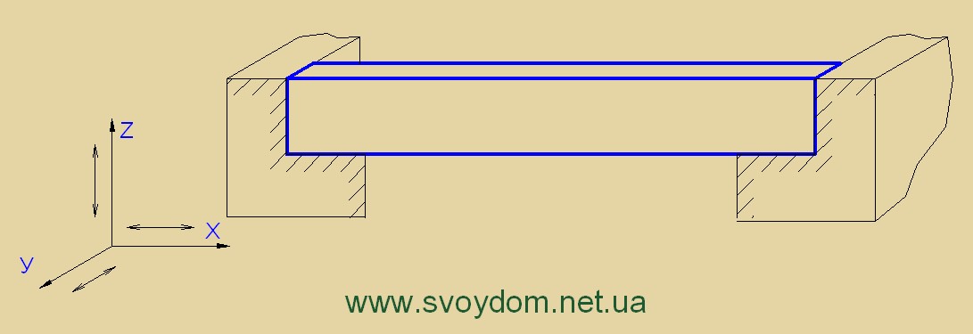
How can any element move in space? Firstly, it can be moving along one of three planes - vertically (Z-axis), horizontally (X and Y axes). Secondly, it can be a rotation of the element in the node around the same three axes.
Thus, we have as many as six possible movements (and if we also take into account the plus or minus direction, then there are not six, but twelve of them), which are also called degrees of freedom - and this is a very descriptive name. If the structure is hanging in the air (an unrealistic situation), then it is completely free, not limited by anything. If a support appears in some place below it, preventing it from moving vertically, then one of the degrees of freedom of the element at the place of support is limited along the Z axis. An example of such a restriction is the free support of a metal beam on a smooth, slippery surface - it will not fall due to the support, but can, with a certain effort, move along the X and Y axes, or turn around any axis. Looking ahead, let's clarify an important point: if an element in a node has no rotation constraint, the node is articulated. So, such a simple hinge with a limitation along only one axis is usually denoted as follows:

It is easy to decipher such a designation: circles mean the presence of a hinge (i.e., the absence of a ban on the rotation of an element at this point), a wand means a ban on movement in one direction (usually it becomes immediately clear from the diagram - in which one - in this case, a vertical ban). A hatched horizontal symbolizes the presence of a support.
The next option for limiting the degrees of freedom is the prohibition of movement in the direction of two axes. For the same metal beam, these can be the Z and X axes, and along Y it can move when a force is applied to it; its turns, as you can see, are also not limited by anything.
How to imagine the absence of restriction of turns? If you try to spin this beam around its own axis (for example, lean the ceiling on it only on one side - then the beam will begin to spin under the weight of the ceiling), then nothing will prevent this torsion, the beam along its entire length will begin to tip over under the action of a torsional force. In the same way, if a vertical load is applied in the center of the beam, the beam will bend and, at the points of support, will freely rotate around the Y axis (clockwise on the left, counterclockwise on the right). This is what we understand as a hinge.
|
Spoiler:"Important nuances in the design of support nodes" |
|
I would like to immediately make a reservation that in the construction of ideal hinges and pinches do not happen. There is always some condition. Let's say we ignore the friction force and assume that the movement of the beam along the Y axis is not limited by anything. With experience usually comes the ability to see if the knot is rigid or hinged. It is also very important to learn how to avoid incomplete pinching (when, with small efforts, there is no rotation of the structure, and with an increase in the acting force, the support does not withstand, and the rotation occurs). Such situations provoke unpredictable behavior of the structure - it was considered for one design scheme, but you have to work according to another. Suppose there is a rigid beam support in the frame, which is provided by welding the beam to the column. But the welded joint is calculated incorrectly and the seam does not withstand the applied force and collapses. The beam continues to rest on the column, but can already turn on the support. In this case, the diagram of bending moments changes dramatically: on the supports, the moments tend to zero, but the span moment increases. And the beam was designed for pinching and was not ready to perceive the increased moment. This is how destruction happens. Therefore, rigid nodes must always be designed for the maximum possible load. |
Such a hinge is designated as follows.
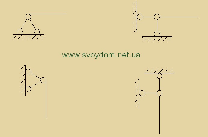
Left and right notations are equivalent. On the right, it is more visual: 1 - a horizontal rod is limited in the node in moving vertically (vertical stick with circles at the ends) and horizontally (horizontal stick with circles at the ends); 2 - the vertical rod is also limited in the node in moving vertically and horizontally. On the left is also a very common designation of exactly the same hinge, only the sticks are arranged in the form of a triangle, but the fact that there are two of them means that the movement is limited along two axes - along the axis of the element and perpendicular to its axis. Particularly lazy comrades may not draw circles at all, and designate such a hinge simply as a triangle - this also occurs.
Now consider what the classic designation of a hinged beam means.
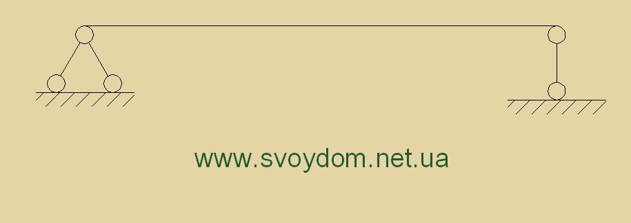
This is a beam that has two supports, and on the left it is also limited in horizontal movement (if this were not the case, the system would not be stable - there is such a condition in the strength of materials - the rod must have three movement restrictions, in our case two restrictions on Z and one X). The designer must consider how to ensure that the support of the beam complies with the design scheme - this should never be forgotten.
And the last case for a plane problem is the restriction of three degrees of freedom - two displacements and rotation. It was said above that for any element there are six (or twelve) degrees of freedom, but this is for a three-dimensional model. We usually consider a plane problem in the calculation. And here we come to the restriction of rotation - this is a classic concept hard node or pinching- when at the point of support the element can neither move nor turn. An example of such a node can serve as a team termination node reinforced concrete column into a glass - it is so deeply monolithic that it has no opportunity to either move or turn around.
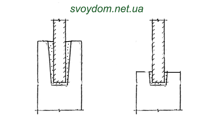
The embedment depth of such a column is strictly calculated, but even in appearance we cannot imagine that the column in the figure on the left can turn in a glass. But the right column is easy, it is an obvious hinge, and it is unacceptable to design a pinch in this way. Although both there and there the column is immersed in a glass and the groove is filled with concrete.
More pinching options will be in the course of the article. Now let's deal with the notation of pinching. It is classic, and there is no particular variety, unlike hinges.

On the left is a horizontal element clamped on a support, on the right is a vertical element.
And finally - about the articulated and rigid nodes in the frames. If the beam-to-column connection node is rigid, then it is shown either without symbols at all, or with a filled triangle in the corner (as in the top two figures). If the beam rests on the columns pivotally, circles are drawn at the ends of the beam (as in the lower figure).

How to Design a Hinged or Rigid Knot
Supporting plates, beams, lintels.
The first thing to remember when designing nodes is that often a hinge is distinguished from a pinch by the depth of support.
If a slab, lintel or beam is supported at a depth equal to or less than the height of the section, and no additional measures have been taken (welding to embedded elements that prevent rotation, etc.), then this is always a clean hinge. For metal beams is considered to be articulated by 250 mm.
If the support is more than two - two and a half heights of the section of the element, then such support can be considered as pinching. But there are nuances here.
Firstly, the element must be loaded from above (with masonry, for example), and the weight of this weight must be sufficient to absorb the force in the element on the support.
Secondly, another solution is possible, when the rotation of the element is limited by welding to embedded parts. And here it is necessary to clearly understand the features of the design of rigid nodes. If the beam is either welded at the bottom (this is often found both in metal structures and in precast concrete - mortgages in the beam or slab are welded to the mortgages in the support), then this does not prevent it from turning on the support - it only prevents the horizontal movement of the element, about this we said above. But if the upper part of the beam is securely anchored by welding on a support (these are either frame nodes in metal, or bath welding of the upper outlets of reinforcement in prefabricated crossbars - in rigid frame nodes, or welding of embedded elements in the support nodes of balcony slabs, which must be pinched, since they are console), then this is already a hard node, because clearly prevents rotation on the support.
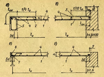
In the figure below, hinged and rigid assemblies are selected from standard series (series 2.440-1, 2.140-1 issue 1, 2.130-1 issue 9). They clearly show that in a hinged joint, the fastening goes at the bottom of a beam or slab, and in a rigid one, at the top. Clarification: in the slab support node, the anchor does not provide a rigid node, it is a flexible element that only prevents the horizontal displacement of the floor.

But designing a knot correctly is half the battle. It is also necessary to make a calculation of all the elements of the node, whether they can withstand the maximum force transmitted from the element. Here it is necessary to calculate both embedded parts and welds, and check the masonry if the weight from it is taken into account in the design.
Connection of columns with foundations.
When supporting metal columns, the determining factor is the number of bolts and how the base of the column is designed. I will not expand on metal here, because. this is not my profile. I will only write that if there are only two bolts in the foundation for attaching the column, then this is a 100% hinge. Also, if the post is welded to the foundation embedded part through the plate, this is also a hinge. The remaining cases are detailed in the literature, there are nodes in typical series - in general, there is a lot of information, it is difficult to get confused here.
For prefabricated reinforced concrete columns, their rigid embedment in the foundation glass is used (this was discussed above). If you open the "Manual for the design of foundations on a natural foundation for columns of buildings and structures", there you can find the calculation of all the elements of this rigid node and the principles of its design.
With a hinged joint, the column (pillar) simply rests on the foundation without any additional measures or is embedded in a shallow glass.
Connection of monolithic structures.
AT monolithic structures a rigid knot or hinge is always defined by the presence of properly anchored reinforcement.
If on the support the reinforcement of the slab or beam is not inserted into the structure of the support by the amount of anchoring or even overlapping, then such a node is considered to be hinged.
So the figure below shows the support options monolithic slabs from the Reinforced Concrete Construction Design Guide. Figure (a) and (b) - this is a rigid connection of the slab with the support: in the first case, the upper reinforcement of the slab is inserted into the beam for the length of the anchorage; in the second case, the slab is pinched in the wall also by the amount of anchoring of the working reinforcement. Figure (c) and (d) - this is the hinged support of the slab on the beam and on the wall, here the reinforcement is brought to the support to the minimum allowable support depth.
Frame nodes connecting monolithic crossbars and columns in reinforced concrete look even more serious than the support of slabs on beams. Here, the upper reinforcement of the crossbar is inserted into the column by the value of one and two anchoring lengths (half of the rods are inserted into one length, half - into two).

If in node reinforced concrete frame the reinforcement of both beams and columns passes through and goes further than the length of the anchoring (for example, some kind of middle node), then such a node is considered rigid.
In order for the connection of columns to the foundation to be rigid, outlets of sufficient length must be made from the foundations (at least the amount of overlap, for more details, see the Design Guide), and the same outlets must be inserted into the foundation to the length of the anchorage.
Similarly in pile grillage- if the length of the protrusions from the pile is less than the length of the anchorage, the connection between the grillage and the pile cannot be considered rigid. For a hinged connection, the length of the outlets is left 150-200 mm, it is no longer desirable, because. this will be the boundary state between the hinge and the rigid joint - and after all, the calculation was done as for a pure hinge.
If there is no space to place reinforcement for the length of the anchorage, additional measures are taken - welding washers, plates, etc. But such an element must be necessarily designed for puncturing (something like the calculation of anchors for embedded parts, it can be found in the Reinforced Concrete Design Guide).
You can also read on the topic of hinges and pinching.
Page 1
The pivotally movable support (support B in Fig. 118) makes it possible, in addition to rotations, to move the end of the beam parallel to the reference plane. In accordance with this, the reaction of such a support passes through the center of the hinge and.
The first type is a cylindrical movable or pivotally movable support. It consists of an upper balancer attached to the system, a lower balancer, a cylindrical hinge placed between the balancers, and rollers that can move along the reference plane. Such support allows rotation of the system around the hinge and translational movement along the support plane.
The cross section of the beam passing through the pivotally movable support can be displaced parallel to the reference plane / - / and rotated, but it cannot be displaced perpendicular to the reference plane. Only one reaction occurs in the support - in the form of a force R perpendicular to the support plane. Fixing a beam with such a support imposes one connection on it.
The cross section of the beam passing through the pivotally movable support can be displaced parallel to the reference plane / - / and rotated, but it cannot be displaced perpendicular to the reference plane. In the support, only one reaction occurs - in the form of a force R perpendicular to the support plane. Fixing a beam with such a support imposes one connection on it.
When calculating beams, there are three main types of supports (three types of fixing the ends of the beams): hinged movable support; pivotally fixed support; rigid termination of the end of the beam.
The fact that the main parametric resonance occurs at 0 2Q is easy to explain - in the time it takes for any point of the beam axis to complete one cycle of oscillation, the center of the section coinciding with the pivotally movable support performs two cycles of oscillation along the axis of the rod.
The right free end of the real beam in this section of the fictitious beam corresponds to the termination. In the section above the pivotally movable support, the deflection of the real beam is equal to zero, and the angle of inclination is different from zero. Therefore, a hinge should be introduced into this section of the fictitious beam, in which the fictitious bending moment M is always equal to zero, and the fictitious transverse force Q is different from zero.
The pivotally movable support (Fig. 7.6) allows the beam to move in the horizontal direction and the beam to rotate relative to the support at a certain angle cf. In accordance with this, only a vertical reaction occurs in a pivotally movable support, which will be denoted by R. Fastening a beam with such a support imposes one connection on it.
The design schemes of the shafts and axles of the gearboxes are presented in the form of stepped or smooth beams on hinged supports. Bearings that simultaneously perceive axial and radial loads are replaced by pivotally fixed bearings, and bearings that perceive only radial forces are replaced by pivotally movable bearings. The position of the hinged support is determined taking into account the contact angle of the rolling bearing axes (c. At a 0 for radial bearings, the position of the support is taken in the middle of the bearing width. The axes of the satellites that do not rotate relative to the load vector can be considered as statically indeterminate beams with an elastic seal.
| Reduction of stress concentration at the landing site with a guaranteed tightness.| Rational form of splined sections of shafts. |
The design schemes of the shafts and axles of the gearboxes are presented in the form of stepped or smooth beams on hinged supports. Bearings that simultaneously perceive axial and radial loads are replaced by pivotally fixed bearings, and bearings that perceive only radial forces are replaced by pivotally movable bearings. The position of the hinged support is determined taking into account the contact angle of the rolling bearing axes (c. At a 0 for radial bearings, the position of the support is taken in the middle of the bearing width. The axes of the satellites that do not rotate relative to the load vector can be considered as statically indeterminate beams with an elastic seal.
Consider now a section of a real beam with an intermediate hinge. In this section, the deflection and the angle of inclination are not equal to zero. Moreover, the hinge allows a break in the curved axis of the beam, therefore, the angles of inclination of the tangent to the left and right of the hinge must be different. To satisfy the specified conditions, it is necessary to introduce a pivotally movable support into this section of the fictitious beam. Then the fictitious bending moment M above the support will be different from zero, therefore, the deflection in this section of the real beam will also be different from zero.
Pages: 1


