Calculation of the deflection of a metal beam. Methodology for calculating load-bearing structures made of various materials
Wooden floor beams
Timber beams are often the most economical option. Wooden beams are easy to manufacture and install, have low thermal conductivity compared to steel or reinforced concrete beams. Flaws wooden beams- lower mechanical strength, requiring large sections, low fire resistance and resistance to damage by microorganisms and termites (if they are found in your area). Therefore, wooden floor beams must be carefully treated with antiseptics and flame retardants, for example, XM-11 or HMBB manufactured by Antiseptic (St. Petersburg).
How to calculate the required cross-section of a wooden floor beam?
The optimal span for wooden beams is 2.5-4 meters. The best section for a wooden beam is rectangular with a height to width ratio of 1.4:1. The beams are led into the wall by at least 12 cm and waterproofed in a circle, except for the end. It is advisable to fix the beam with an anchor embedded in the wall.
When choosing a section of a floor beam, the load of its own weight is taken into account, which for beams of interfloor floors, as a rule, is 190-220 kg / m2, and the temporary (operational) load, its value is taken equal to 200 kg / m2. Floor beams are laid along a short section of the span. It is recommended to choose the installation step of wooden beams equal to the installation step of the frame racks.
To calculate the minimum and optimal cross-section of a wooden floor beam, you can use the Romanov online calculator for wooden floor beams
Below are several tables, with the values of the minimum sections of wooden beams for various loads and span lengths:
Table of sections of wooden floor beams depending on the span and installation step, with a load of 400 kg / m2. - it is recommended to rely on this load
If you do not use insulation or do not plan to load floors (for example, an uninhabited attic floor), then you can use the table for lower load values of wooden floor beams:
Table of minimum sections of wooden floor beams depending on the span and load, with loads from 150 to 350 kg / m2.
![]()
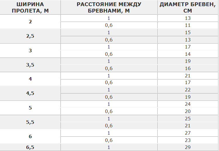
If you use round logs instead of rectangular beams, you can use the following table:
The minimum allowable diameter of round logs used as floor beams depending on the span at a load of 400 kg per 1 m2
If you want to block large runs, we recommend using the experience from the Okolotok website.
Steel (metal) I-beams
An I-beam metal floor beam has a number of undeniable advantages, with only one drawback - high cost. A metal I-beam can cover large spans with a significant load, metal steel beam non-combustible and resistant to biological influences. However, a metal beam can corrode in the absence of a protective coating and the presence of aggressive environments in the room.
To calculate the parameters of an I-beam metal beam you can use good
In most cases, in amateur construction, when calculating in the above program or others similar to it, it should be assumed that the metal beam has articulated supports(that is, the ends are not rigidly fixed - for example, since in the frame steel structure). The load on the floor with steel I-beams, taking into account their own weight, should be calculated as 350 (without screed) -500 (with screed) kg / m2
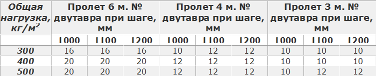
The step between the I-beams is recommended to be equal to 1 meter. In case of economy, it is possible to increase the step between metal beams up to 1200 mm.
Table for selecting the number of an I-beam metal beam with different pitches and lengths of runs
Reinforced concrete floor beams
When constructing reinforced concrete beams, the following rules must be used (according to Vladimir Romanov):
- Height reinforced concrete beam must be at least 1/20 of the length of the opening. Divide the length of the opening by 20 and get the minimum height of the beam. For example, with an opening of 4 m, the height of the beam should be at least 0.2 m.
- The width of the beam is calculated based on the ratio of 5 to 7 (5 - width, 7 - height).
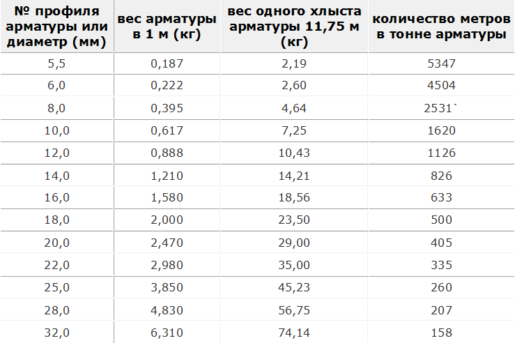
- The beam should be reinforced with at least 4 bars of reinforcement d12-14 (it can be thicker from below) - two at the top and bottom. Tables of the ratio of the length and mass of reinforcement of various sections.
- Concrete at one time, without interruptions, so that the previously laid portion of the mortar does not have time to grab before laying a new portion. Concreting beams with a concrete mixer is more convenient than ordering a mixer. The mixer is good for quickly pouring large volumes.
The weight of building reinforcement or how many meters of reinforcement in a ton. Weight of rebar 11.75 m long. Weight of rebar with a diameter of 5.5 to 32 mm.
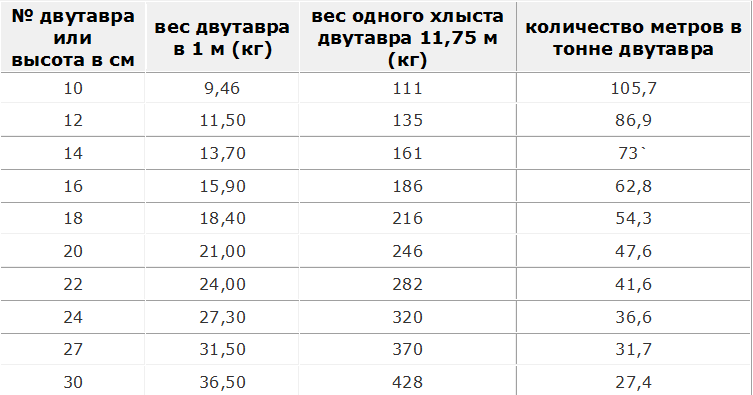
I-beam weight and number of meters per ton of I-beam
Beam - an element in engineering, which is a rod that is loaded by forces acting in a direction perpendicular to the rod. The activities of engineers often include the need to calculate the deflection of a beam under load. This action is performed in order to limit the maximum deflection of the beam.
Types
To date, beams made of different materials. It can be metal or wood. Each specific case implies different beams. At the same time, the calculation of beams for deflection may have some differences that arise on the basis of the difference in structure and materials used.
wooden beams
Today's individual construction implies the widespread use of beams made of wood. Almost every building contains Wooden beams that can be used as load-bearing elements, they are used in the manufacture of floors, as well as supports for floors between floors.
It's no secret that a wooden beam, like a steel beam, tends to bend under the influence of loading forces. The deflection arrow depends on what material is used, the geometric characteristics of the structure in which the beam is used, and the nature of the loads.
The allowable beam deflection is formed from two factors:
- Compliance with deflection and allowable values.
- Possibility of operation of the building taking into account the deflection.
Strength and stiffness calculations carried out during construction make it possible to most effectively assess what loads the building can withstand during operation. Also, these calculations allow you to find out exactly what will be the deformation of structural elements in each specific case. Perhaps no one will argue with the fact that detailed and maximum accurate calculations- this is part of the duties of civil engineers, however, using a few formulas and the skill of mathematical calculations, you can calculate all the necessary quantities yourself.
In order to make a correct calculation of the beam deflection, one must also take into account the fact that in construction the concepts of stiffness and strength are inseparable. Based on the strength calculation data, you can proceed to further calculations regarding stiffness. It should be noted that the calculation of the beam deflection is one of the indispensable elements of the stiffness calculation.
Please note that to carry out such calculations on your own, it is best to use enlarged calculations, while resorting to fairly simple schemes. It is also recommended to make a small margin in the big direction. Especially if the calculation concerns load-bearing elements.
Calculation of beams for deflection. Work algorithm
In fact, the algorithm by which such a calculation is made is quite simple. As an example, let's consider a somewhat simplified calculation scheme, while omitting some specific terms and formulas. In order to calculate beams for deflection, it is necessary to perform a series of actions in a certain order. The calculation algorithm is as follows:
- A calculation scheme is being drawn up.
- The geometric characteristics of the beam are determined.
- The maximum load on this element is calculated.
- If necessary, the strength of the beam in terms of bending moment is checked.
- The maximum deflection is calculated.
As you can see, all the steps are quite simple and quite doable.
Drawing up a design diagram of a beam
In order to compose calculation scheme does not require much knowledge. To do this, it is enough to know the size and shape of the cross section of the element, the span between the supports and the method of support. The span is the distance between two supports. For example, you use beams as floor support beams for the load-bearing walls of a house, between which there are 4 m, then the span will be 4 m. 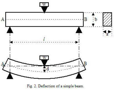
When calculating the deflection of a wooden beam, they are considered freely supported structural elements. In the case for the calculation, a circuit with a load that is evenly distributed is adopted. It is denoted by the symbol q. If the load is concentrated, then a scheme with a concentrated load, denoted by F, is taken. The value of this load is equal to the weight that will put pressure on the structure.
Moment of inertia
The geometric characteristic, which received the name, is important when calculating the beam deflection. The formula allows you to calculate this value, we will give it a little below.
When calculating the moment of inertia, you need to pay attention to the fact that the size of this characteristic depends on the orientation of the element in space. In this case, there is an inversely proportional relationship between the moment of inertia and the amount of deflection. The smaller the value of the moment of inertia, the greater the value of deflection and vice versa. This dependence is quite easy to trace in practice. Everyone knows that a board laid on its edge bends much less than a similar board in its normal position. 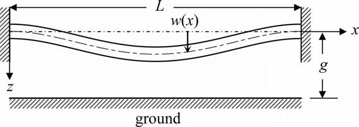
The moment of inertia for a beam with a rectangular section is calculated using the formula:
J=b*h^3/12, where:
b - section width;
h is the height of the beam section.
Maximum Load Level Calculations
The determination of the maximum load on a structural element is made taking into account a number of factors and indicators. Usually, when calculating the load level, they take into account the weight of 1 linear meter of a beam, the weight of 1 square meter of floor, the load on the floor of a temporary nature and the load from partitions by 1 square meter overlap. The distance between the beams, measured in meters, is also taken into account. For an example of calculating the maximum load on a wooden beam, we will take averaged values, according to which the weight of the floor is 60 kg / m², the temporary load on the floor is 250 kg / m², the partitions will weigh 75 kg / m². The weight of the beam itself is very easy to calculate, knowing its volume and density. Let's assume that a wooden beam with a section of 0.15x0.2 m is used. In this case, its weight will be 18 kg / running meter. Also, for example, let's take the distance between the floor beams equal to 600 mm. In this case, the coefficient we need will be 0.6.
As a result of calculating the maximum load, we obtain the following result: q=(60+250+75)*0.6+18=249 kg/m.
When the value is obtained, you can proceed to the calculation of the maximum deflection.
Calculating the value of the maximum deflection
When a beam is calculated, the formula displays all the necessary elements. It should be borne in mind that the formula used for calculations may have a slightly different form if the calculation is carried out for different types loads that will affect the beam.
First, let's bring to your attention the formula used to calculate the maximum deflection of a wooden beam with a distributed load.
f=-5*q*l^4/384*E*J.
Please note that in this formula, E is a constant value, which is called the modulus of elasticity of the material. For wood, this value is 100,000 kgf / m².
Continuing the calculations with our data used for the example, we get that for a beam made of wood, the cross section of which is 0.15x0.2 m, and the length is 4 m, the value of the maximum deflection when exposed to distributed load equal to 0.83 cm.
Please note that when the deflection is calculated taking into account the scheme with a concentrated load, the formula takes the following form:
f=-F*l^3/48*E*J, where:
F is the pressure force on the beam. 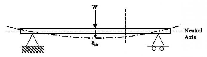
We also pay attention to the fact that the value of the modulus of elasticity used in the calculations may differ for different types wood. The influence is exerted not only by the type of wood, but also by the type of timber. Therefore, a solid beam made of wood, glued beams or logs will have different moduli of elasticity, and hence different meanings maximum deflection.
You can pursue different goals when calculating beams for deflection. If you want to know the limits of deformation of structural elements, then after completing the calculation of the deflection arrow, you can stop. If your goal is to establish the level of compliance of the found indicators with building codes, then they need to be compared with the data that are placed in special regulatory documents.
I-beam
Please note that I-beams are used somewhat less frequently due to their shape. However, you should also not forget that such a structural element can withstand much greater loads than a corner or a channel, an alternative to which can be an I-beam.
Calculating the deflection of an I-beam is worth doing if you are going to use it as a powerful structural element. 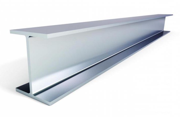
We also draw your attention to the fact that not for all types of I-beams it is possible to calculate the deflection. In what cases is it allowed to calculate the deflection? There are 6 such cases in total, which correspond to six types I-beams. These types are:
- Beam of single-span type with uniformly distributed load.
- Cantilever with rigid termination at one end and evenly distributed load.
- A single-span beam with a cantilever on one side, to which a uniformly distributed load is applied.
- Single-span beam with hinged support type with concentrated force.
- Single-span hinged beam with two concentrated forces.
- Cantilever with rigid termination and concentrated force.
metal beams
The calculation of the maximum deflection is the same, whether it is a steel beam or an element made of another material. The main thing is to remember those values that are specific and constant, such as the modulus of elasticity of the material. When working with metal beams, it is important to remember that they can be made of steel or I-beams. 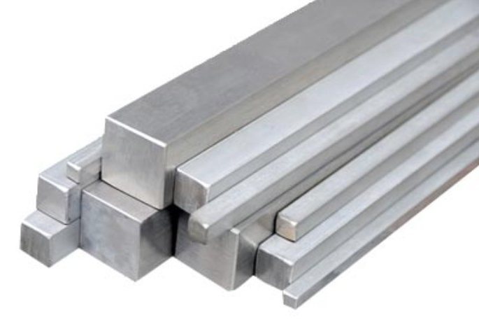 The deflection of a metal beam made of steel is calculated taking into account that the constant E in this case is 2 105 MPa. All other elements, such as the moment of inertia, are calculated according to the algorithms described above.
Calculation of the maximum deflection for a beam with two supports
As an example, consider a scheme in which a beam is on two supports, and a concentrated force is applied to it at an arbitrary point. Before the force was applied, the beam was a straight line, but under the influence of the force it changed its appearance and, due to deformation, became a curve. 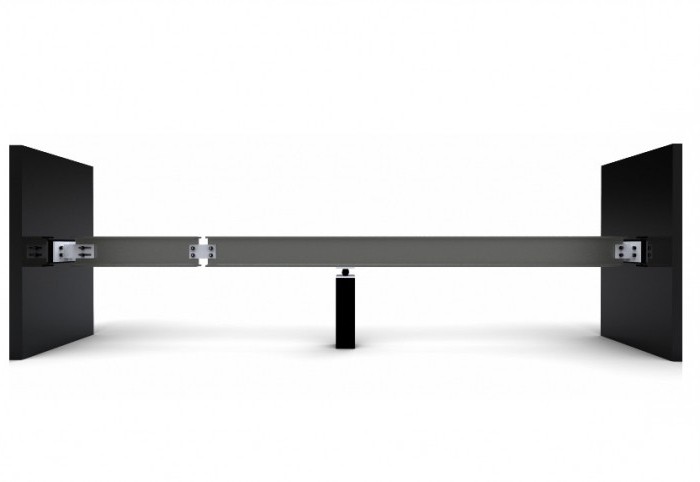
Let us assume that the XY plane is the plane of symmetry of the beam on two supports. All loads act on the beam in this plane. In this case, the fact will be that the curve resulting from the action of the force will also be in this plane. This curve is called the elastic line of the beam or the line of deflection of the beam. Algebraically solve the elastic line of the beam and calculate the deflection of the beam, the formula of which will be constant for beams with two supports, as follows.
Deflection at a distance z from the left beam support at 0 ≤ z ≤ a
F(z)=(P*a 2 *b 2)/(6E*J*l)*(2*z/a+z/b-z 3 /a 2 *b)
Beam deflection on two supports at a distance z from the left support at a ≤ z ≤l
f(z)=(-P*a 2 *b 2)/(6E*J*l)*(2*(l-z)/b+(l-z)/a-(l-z) 3 /a+b 2), where P is the applied force, E is the modulus of elasticity of the material, J is the axial moment of inertia.
In the case of a beam with two supports, the moment of inertia is calculated as follows:
J=b 1 h 1 3 /12, where b 1 and h 1 are the values of the width and height of the section of the used beam, respectively.
Conclusion
In conclusion, we can conclude that it is quite simple to independently calculate the value of the maximum deflection of beams of different types. As shown in this article, the main thing is to know some characteristics that depend on the material and its geometric characteristics, as well as to carry out calculations using several formulas in which each parameter has its own explanation and is not taken from nowhere.
And the collapse of buildings is necessary to perform the calculation of the data load-bearing structures. Beams are made of wooden beams, rolled metal and reinforced concrete. Below are the simplest calculation methods and recommendations for choosing beams from these materials.
Calculation of wooden beams
To calculate wooden beams, you need to know the distributed load on, the length of the beams and the distance between them. The beams are laid parallel to the short side of the building, the distributed load is chosen to be 400 kg/sq. meter for interfloor and 200 kg / sq. meter for attic floors. For example, we calculate the beams for a room with dimensions of 6x4.5 meters, while the length of the beam will be about five meters, but the calculation is based on the distance between the walls - 4.5 meters. The distance between the beams is chosen equal to 0.8 meters.
Calculate the maximum bending moment:
M \u003d (q x hxl2) / 8 \u003d 400 x 0.8 x 4.52 / 8 \u003d 810 kgm \u003d 81000 kgcm;
where q is the distributed load, h is the distance between the beams; l is the span length.
The required modulus of the beam is:
W \u003d M / R \u003d 81000 / 142.71 \u003d 567.6 cu. cm;
where R is the design resistance of wood, for pine equal to 14 MPa or 142.71 kgf / sq. cm.
By setting the width of the beam section (10 cm), we determine the height of the beam:
h \u003d √ (6W / b) \u003d √ (6 x 567.6 / 10) \u003d 18.5 cm;
where h is the height, b is the width of the beam. The calculation results show that a 10x20 cm beam can be used.
The optimal ratio of the width and height of the beam is 1:1.4. Substituting in the formulas different values of the distances between the beams and their widths, we calculate the consumption of materials and choose the most economical option with the optimal section.
To select wooden beams, you can use the Romanov online calculator or tables that show the most typical options based on the results of the calculations. Similar materials can be easily found on the Internet.
The deflection of a wooden beam must be less than 1/250 of its length, in our case 450/250 = 1.8 cm. It is calculated by the formula:
f \u003d (5ql4) / (384EI) \u003d 5 x 400 x 4.5 x 4.5 x 4.5 x 4.5 / 384 x 109 x 6666.6667 x 10 - 8 \u003d 3.2 cm;
where E is the modulus of elasticity, for wood equal to 109 kgf/m2; I - moment of inertia, for a rectangular beam equal to:
![]() I \u003d b x h3 / 12 \u003d 10 x 203 / 12 \u003d 6666.6667 cm4.
I \u003d b x h3 / 12 \u003d 10 x 203 / 12 \u003d 6666.6667 cm4.
In this case, the deflection is greater than the allowable one, so you should choose a beam with a larger section or reduce the distance between the beams and repeat the calculations.
The methodology for determining the maximum bending moment and the moment of resistance is the same for beams of any material. Metal beams are most often made of I-beams. The value of the permissible moment of resistance for the selected profile can be found in the rolled metal reference or calculated on online calculator by geometric dimensions. Calculations are greatly facilitated by using programs available on the Internet. The table shows the recommended numbers of I-beams with a distributed load of 400 kgf / sq. m.
Calculation of reinforced concrete beams
Factory beams are selected according to the allowable moment of resistance, which is indicated in the documentation. The choice of the design of monolithic beams is complicated by the fact that reinforced concrete is a material consisting of several components and it is quite difficult to foresee the influence of all factors on the bearing capacity of the beam. The calculation methodology can be mastered only by specialists who have studied strength of materials and have practical experience.- Concrete can withstand significant compressive loads, and reinforcement can withstand tension, so it is installed in the tension zone - the bottom of the beam.
- The height of the beam section is chosen greater than 1/20 of the span length, the ratio of the height to the width of the section is equal to 7:5.
- The diameter of the reinforcement should be 12 mm or more, the number of bars should be at least 4, thicker reinforcement is laid in the lower part of the section (the reinforcement in the upper part is needed if the beam is made on the ground and is installed in place by a crane).
- Concreting should be carried out in one step, the next portion of concrete is laid before the previous one sets.
- The choice of beams is simplified when using programs that determine their cross section and the amount of reinforcement.
Conclusion
The above formulas and recommendations give an idea of the calculation methodology and, in most cases, are suitable for choosing floor beams. More sophisticated techniques take into account all operating conditions, while checking for resistance to loads acting in different directions.
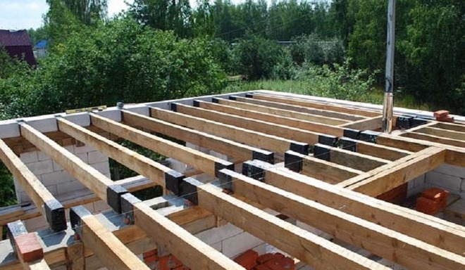
During the construction of private residential buildings, outbuildings and other buildings, it is important to correctly calculate the parameters of each structural element. One of the key elements of any wood structure is the floor.
About floor materials
Properly selected material, choice of length, section and installation scheme determines its durability and the loads that it can withstand. The selection and calculation of wooden beams for floors between floors is one of the most important decisions in private construction. Since wood is an environmentally friendly material and quite durable.
The only supposed minus of wood when compared with concrete is its combustibility, the indicator of which, if necessary, can be reduced if the wood is treated with special compounds.
It is generally accepted that concrete is refractory, although this is not entirely true: it cracks at temperatures above 250 and crumbles at a temperature of 550 degrees, that is, it is completely destroyed in a fire. Therefore, wood is a good alternative to concrete.
But, in order to calculate how much wood is needed for construction, so that there is no excess of it, so that the maximum load bearing capacity this wooden beam, often use a calculator for automatic calculation of floor parameters. The calculator for calculating wood floor beams will help you quickly and fairly accurately determine the safety margin when using different materials and, accordingly, choose one of them. The best materials, section parameters, design features, high-quality floor beams allow you to optimally distribute the load without exceeding the permissible one, as well as walls made of brick or made of other material.
What determines the strength of the coating?
The main parameters that affect the quality of the overlap depend on the properties of the material, technical parameters and operating conditions.
Properties of wood materials:
- Type of tree. Pine, spruce, larch are considered popular species for use in residential construction. Sometimes oak, birch, aspen, as well as combined materials are used.
- Sort. Three types of wood are determined, which are numbered 1 (the best), 2 and 3. The grade is determined by the maximum number of knots on the wood, the bending of the beams, including healthy and rotten ones, the number, depth and length of cracks, and other wood defects. Detailed requirements for wood are determined by standards, norms, rules (SNiP II-25-80, SP 64.13330.2011 and others).
Each material has its own strength and deflection characteristics, which depend on the technical parameters described below. Some breeds are lighter, others more resistant to moisture.
For example, softwoods have better resistance to moisture. The first grade of wood is of the best quality, lack of flaws, but it is correspondingly more expensive.
Technical indicators:
- Beam type. Defines types such as rectangular beams, round logs, beams,. glued from boards or LVL veneer.
- Span length. Typically, a beam span for private residential buildings is no more than 6 meters. It is important to remember that this indicator is different from the length of the beam itself, which must also capture the supporting sections on the walls or other supports.
- Beam height and width. For a beam, another rectangular beam, these indicators may be the same or different. The greater their height, the greater the rigidity and the less they flex. In the case of logs, the diameter or average diameter of the log is taken into account. When choosing these parameters, the features and ease of manufacture, transportation, and installation of beams are also taken into account.
- Beam step. This is the distance between two adjacent beams in the floor. The closer the beams, the higher their consumption of beams, the strength of the overlap, but the deflection and maximum load decrease. and concentrated load, which are defined by standards and depend on the type of premises, the number of residents or employees, the type and amount of furniture or equipment in them, and other features of their use.
- Cover type. This refers to interfloor floors with increased requirements for relative deflection, which is 1/250; attic floors, the requirements for which are lower - 1/200; coatings and floorings, the relative deflection of which is 1/150.
The last 3 items are also defined as operating conditions hardwood floor, which depend directly on the features of the construction.
Result and calculation example
How the wooden beam calculator works and how the load is calculated are the main questions to be answered here.
The 2 main indicators that determine the quality of the floor are the distributed load on the floor itself, as well as the concentrated load on the crossbars, if they are used. The quality of the crossbar also depends on the method of fixing it.
The online calculator automatically shows how large the reserve of distributed load and deflection at the floor will be. Or vice versa, it will indicate an overload.
Calculation example
For example, the following input parameters are used: pine timber, single-span for interfloor overlapping, 6 meters long, has a square section of 120 by 120 millimeters. They will be located in increments of 40 centimeters with a load on the beam, which is 60 kilograms per square meter.
The moment of inertia of the section will be 1728 cm⁴, and such beams weigh 43 kilograms each.
As a result, the calculated deflection of such an overlap will be 23 millimeters (or 1/261 of the relative deflection). It will have a deflection margin of 1.04 times and collapse under a load of 845 kilograms.
For the corresponding crossbar with a concentrated load of 90 kg, the calculated deflection will be 23 millimeters, and the deflection margin will be 1.04 times. The design will not withstand loads over 422 kilograms.
Consequently, building experts will recommend not to use a floor between floors with such indicators, since the deflection margin is too small.
The optimal deflection index is from 1.5 to 3, respectively. The higher this indicator, the higher the wood consumption, but the lower the deflection margin, the less stable the building as a whole and its elements in particular will turn out.
Benefits of a calculator
Using the calculator, the builder can independently select the necessary parameters, selecting each of the available or desirable options and calculating more profitable materials and type of beams.