Articulated support. Columns. Crane and strapping beams
n1.doc
23 Beams and beam structures, classificationMost common element steel structures bending.
The scope of beams is very wide: from small elements of work sites, interfloor floors of industrial or civil buildings to large-span beams of roofs, bridges, heavily loaded crane beams and the so-called "spinal" beams for suspension of boilers in modern thermal power plants.
Classification:
1.By static schema: 1.single-span (slit) - easier installation and manufacture. 2. multi-span (continuous) - less metal consumption by 20%. 3. cantilever (cut, continuous).
2. By type of section: 1. rolled. 2. composite (welded, riveted, bolted).
More often in construction - I-sections (convenience in line-up, technologically advanced and economical in terms of material consumption). The economic efficiency of sections is related to their thinness.
A measure of efficiency, i.e., the profitability of a beam section as a bending structure, is the ratio of the moment of resistance to the cross-sectional area, equal to the core distance p= W/ A.
A comparison of the core distances of round, rectangular and I-sections, shown in Fig. the best way corresponds to the distribution of normal stresses from beam bending.
In construction, thin-walled beams, beams made of bent profiles, extruded, composite of aluminum alloys, as well as bisteal beams, that is, beams welded from two grades of steel, and prestressed beams, have found application.
24 Beam cages, junction nodes
Beam cells are divided into three main types: simplified (a), normal (b) and complicated (c).

In a simplified beam cage, the floor load is transferred through the flooring to the floor beams, which are usually located parallel to the smaller side of the floor at distances a (beam spacing) and through them to walls or other bearing structures that bound the area. Due to the small bearing capacity flooring, the beams supporting it have to be installed often, which is rational only for small spans.
In a normal beam cage, the load from the deck is transferred to the deck beams, which in turn transfer it to the main beams supported by columns, walls, or other load-bearing structures that bound the site. Floor beams are usually taken as rolling.
In a complicated beam cage, auxiliary beams are introduced, located between the deck beams and the main beams, which transfer the load to the columns. In this type of beam cage, the load is transferred to the supports for the longest time. Floor beams and auxiliary beams are usually taken for hire.
The choice of the type of beam cage is connected with the question of the pairing of beams with each other in height. The conjugation of beams can be storey, at the same level and lowered.


In case of floor junction (a), the beams that directly support the flooring are laid on the main or auxiliary ones. This is the simplest and most convenient way of connecting beams in terms of installation, but it requires the highest building height.
When mating at the same level (b), the upper flanges of the deck beams and the main beams are located at the same level, and the deck rests on them. This method makes it possible to increase the height of the main beam at a given construction height of the ceiling, but significantly complicates the design of the support of the beams.
Reduced conjugation (c) is used in complex type beam cages. In it, auxiliary beams are adjacent to the main one below the level of the upper belt, beams with flooring are laid on them floor by floor. This type of interfacing, as well as interfacing in one level, allows you to have the highest height of the main beam for a given construction height of the floor.
All considered beam interfaces work as articulated ones. If necessary, a rigid pairing of beams is introduced by "fish" (with the same height of the beams) or "fish" and a table (with different heights of the beams). In such a conjugation, not only a transverse force arises, which is transmitted to the bolts that attach the wall of the auxiliary beam to the edge of the main beam or directly to the table, but also a support moment transmitted through special overlays of the fish or through the "fish" and the table.
25 Selection of the section of rolled beams
Maximum bending moment in the beam:
M max \u003d ql 2 / 8, where l is the length of the beam, q is the design load on the beam
Required moment of resistance:
W tr \u003d M max / ? c R y , where? c-factor. working conditions, R y - design resistance of steel
Select an I-beam by W>W red => I-beam, channel or other number.
1. The strength of the accepted section is not checked, because W x >W tr.
2. We check the rigidity (deflection): f / l \u003d (5q n * l 3) / (384EJ x)?
- relative ultimate strain, E - modulus of elasticity of steel
3. Endurance test: ? max??Ry? y , where? - coefficient, taking into account the number of loading cycles, R y - design fatigue resistance, y-coefficient, taking into account the type of loaded state.
4. Testing for strength taking into account brittle fracture? max ??R u /? u, ? max - the highest tensile stress, α-coefficient, depending on the operation t and the type of stress concentrate.
26 Selection of the section of welded beams

beam height is determined from two conditions: a) h?h min , b) h?h opt
The minimum height that provides the condition for ensuring the relative deflection:
 , where R y is the design resistance, l is the length of the beam, E is the elasticity model, = 400 is the reciprocal of the allowable deflection
Optimum main beam height  , where k = 1.1 is the coefficient taking into account the design of the main beam (welded)
Required moment of resistance W tr \u003d M max / s * R y
T w = 7+3*h min, where h min is in meters, t w is in millimeters.
The final height is taken from the condition:
H?h w + 2t f, where h w is the height of the beam web, taken according to the assortment for sheet steel, t f = 20 ... 30 mm.
Section layout
The wall thickness is determined from 2 conditions:
Ensuring shear strength of the wall:
 ; where R s \u003d 0.58 R y is the design shear resistance of steel.
 2) t w ? 7+3*h, where h is the accepted actual height of the beam in meters; t w - in millimeters.
We accept t w according to GOSTs for strip steel.
Determining the width of the girdle sheet
Required area of one belt sheet:
A f tr \u003d (W tr / h) - (t w * h / 6)
Required belt width:
B f tr = A f tr /t f
To ensure the stability of the belt, the following conditions must be met:
1)  2)
2)  ,
,  , Where
  - belt overhang
Geometric characteristics of the accepted section

Checking the selected section for strength:
27 Changing the section of welded beams
If the beam section is left constant along the length, then wherever the bending moments are less than the calculated one, the sections will be underloaded, and the beam as a whole is uneconomical. To save metal, it is advisable to change the beam sections in accordance with the diagram of bending moments.
It is most advisable to change the width of the belts.
The place of change in the section for a hinged beam under a uniformly distributed load is at a distance x = l/6 from the support. For a beam loaded with a concentrated force in the middle, this distance is x = l/4 .
Required section modulus of the modified section:
W№ x tr = M№/R wy , where R wy = R y is the calculated resistance of the deposited metal in the weld, subject to full control over the quality of the weld; M№ - bending moment at the site of the change in the section.
Calculated forces at the site of cross-section change:
Required moment of inertia of the section at the place of change:
J№ x tr = W№ tr *h/2
Required moment of inertia of the belts at the site of the change in the section:
J№ f tr = J№ x tr - J w , where J w is the moment of inertia of the wall 
Required cross-sectional area of one belt sheet at the site of the cross-section change:
 , where h f is the distance between the centers of gravity of the belt sheets
The required width of the girdle sheet at the site of the change in the section:
B№ f tr = A№ f tr /t f
To ensure the strength of the modified section, the following condition must be met: W№ x > W№ x tr
Actual characteristics of the modified section:
J№ x = J w +2*A№ f tr (h- t f) 2
W№ x = J№ x /(h/2)
28 Ensuring the overall stability of welded beams
General stability composite beams check according to the formula M /? b Wc?R? Where? b for I-beams composite beams having two axes of symmetry, as well as in rolling beams, is calculated from  , which in turn is determined in the coefficient function?. Required for definition? parameter?, depending on the resistance of the beam to torsion, for composite beams is calculated by the formula? \u003d 8 (l 0 t p / h 0 b p) 2 (1+ at st 3 / b p t p 3), where l 0 is the effective length compressed beam chord secured against transverse displacements; a = 0.5h0; h 0 - distance (height) between the axes of the belt sheets; b p and t p - respectively, the width and thickness of the compressed belt; t st - beam wall thickness.
For beams with a cross section other than an I-beam, which has two axes of symmetry, the stability check has its own characteristics and should be carried out in accordance with the instructions of SNiP. The overall stability of the beams can be omitted when transferring the load through a solid rigid deck, continuously supported by the compressed beam chord and securely connected to it, as well as when satisfying the conditions of the formula on the ratio of the effective length to the width of the compressed chord.
29 Ensuring local stability of welded beams
Local buckling of individual structural elements under the action of compressive normal or shear stresses is called local buckling.
In beams, the compressed belt can lose stability due to the action of normal stresses and the wall due to the action of tangential or normal stresses, as well as their joint action. The loss of stability of one of the beam elements completely or partially puts it out of operation, the working section of the beam decreases, often becomes asymmetric, the bending center shifts, and this can lead to premature loss of the bearing capacity of the entire beam.
General expression for critical stress
![]()
Beam elements can lose stability only if the stresses acting in the beam or their combined effect are greater than the critical buckling stresses. Therefore undesirable to? cr were less than the design values of the material in terms of strength and the loss of stability occurred before the loss of the bearing capacity of the beam in terms of strength, since in this case the strength of the material would be underused, which is uneconomical.
Stability of a compressed belt. Special constructive measures to ensure an increase in the width of the overhang are impractical.
wall stability. The wall is a long thin plate that is subjected to shear and normal stresses, which can cause the loss of its stability. But the stability of the wall is usually achieved not by increasing its thickness, but by strengthening it with special stiffening ribs located normal to the surface of the buckling of the sheet and increasing the rigidity of the wall.
Stiffening ribs divide the wall into compartments (panels), which can lose stability independently of each other.
The rib in the middle third part of the span of the main beam is installed under each beam above, as well as under the beam closest to the support. In the extreme thirds of the main beams, stiffeners are placed under the rolled beams with a step a? h? . The dimensions of the stiffener are taken according to the assortment for strip steel, while the width of the stiffener b s should not exceed b f /2.
30 Checking the stability of the welded beam web
To ensure the stability of the wall along the span of the beam, transverse double-sided stiffeners are welded to the wall.
The torsional stability of the walls can be omitted if: 
Checking the local stability of the wall
Calculation for the stability of the walls of beams of symmetrical section in the presence of local stress  should be done according to the formula
 ,
,
Where  - determined according to the requirements of SNiP
Determine the actual stresses to check the stability of the beam web  And
And 
The actual value of standard stresses at the level of the top of the wall is determined by the formula:

To check the local stability, we take the average value of shear stresses, provided that they are perceived only by the wall:
local voltage  in the wall under concentrated load
 ,
,
Where F is calculated value load,  - conditional length of load distribution, determined depending on the conditions of support,
The critical stress is determined by the formula:
 , Where
  - conditional wall flexibility
Values 
 , Where
  - coefficient depending on? and the ratios a/h ef
 ,
,
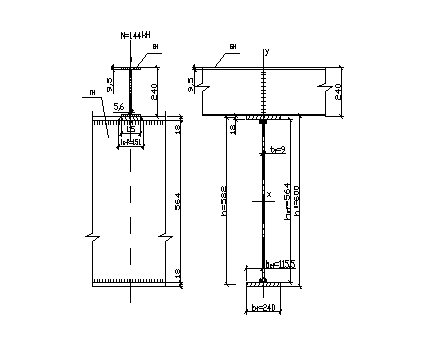
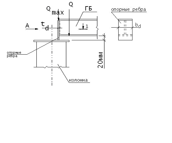
31 Calculation of the support node of the beam on the column from above

The connection of beams with steel columns can be either hinged, transmitting only support reaction beams, or rigid, transmitting to the column, in addition to the support reaction, also the moment of pinching the beam in the column. Swivel is widely used in most beam structures, rigid - in frames multi-storey buildings.
The end of the beam in the place where it rests on the support is reinforced with support ribs, assuming that the entire support reaction is transferred from the beam to the support through these stiffeners. the lower chord of the beam, or planed to directly transfer the support pressure to the steel column. For the correct transmission of pressure to the column, the center of the supporting surface of the rib must be aligned with the axis of the column flange.
The size of the supporting stiffeners is usually determined based on the collapse of the end of the rib
The protruding part of the support rib is usually taken as 15-20 mm.
In addition to checking for collapse of the end of the support rib, the support section of the beam is also checked for stability from the plane of the beam as a conditional support rod, which includes the support ribs and part of the beam wall with a width of 0.65 in each direction and a length equal to the height of the beam web in the design section area: ![]() Where? - buckling ratio of the strut with flexibility (?
=
h CT /
iz),
defined about the axis z,
coinciding with the profile axis of the beam.
Where? - buckling ratio of the strut with flexibility (?
=
h CT /
iz),
defined about the axis z,
coinciding with the profile axis of the beam.
The attachment of support ribs to the beam web by welds shall be designed for the full support reaction of the beam, taking into account the maximum working length of the weld.
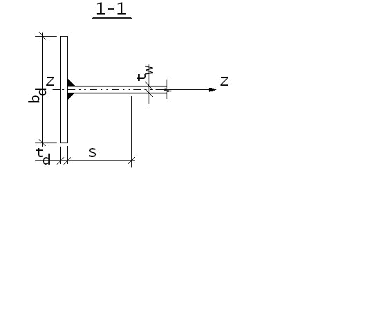
31Calculation of supporting stiffeners
Support rib width: b d \u003d b 1 f \u003d 20 cm.
Required cross-sectional area of the support rib:
 , where Q max is the support reaction in the main beam; R p is the design resistance to crushing of the end surface.
 ,
,  - regulatory resistance in terms of strength,
  - coefficient of reliability for the material.
Required support rib thickness:
T d \u003d A d /b d, where b d \u003d b f
Finally, t d is taken according to the assortment for sheet steel. In addition to crushing, the support rib works in compression, and it is required to check the stability of the conditional rack. The cross section of the conditional post includes a support rib and a part of the wall.
The length of this part of the wall is determined by the formula: 
The cross-sectional area of the conditional rack is found by the formula: 
The stability check is reduced to the fulfillment of the condition = Q max /(*A s) ? R y ; where is the buckling coefficient. Accepted depending on the flexibility z:
z = h w /i z , where i z is the radius of inertia of the conditional rack section,

J z - moment of inertia of the conditional rack section 
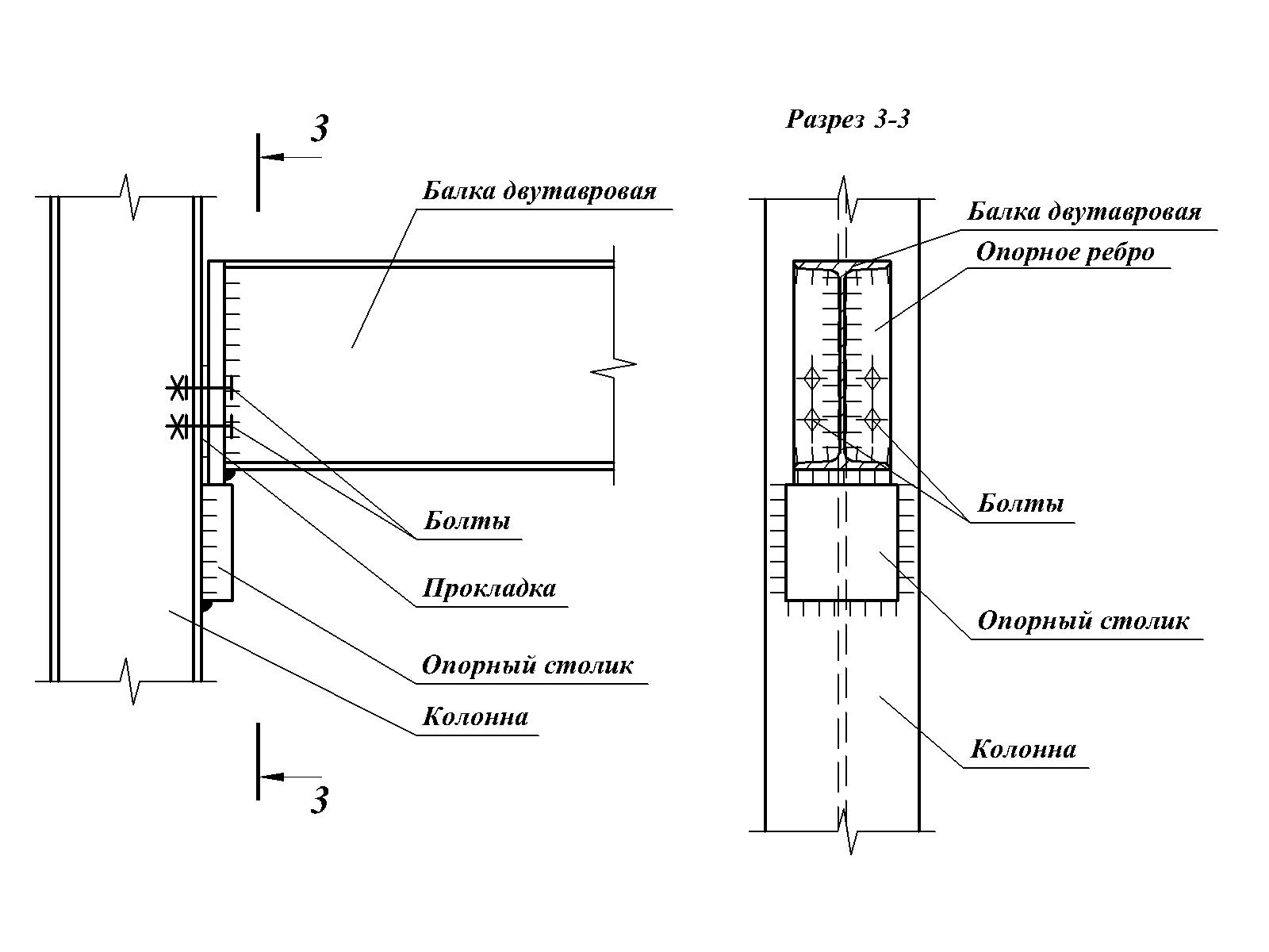
32 Calculation of the support node of the beam on the column on the side and on brick walls
Hinged connection of a beam to a column:
When the beam is hinged to the column, the support reaction is transmitted through the support table, which, depending on the load, is made from a sheet 25-40 mm thick or from an unequal angle with a cut smaller shelf, or from a welded T-section table. The seams securing the support table are calculated for shear or for shear and bending, taking into account the working conditions coefficient equal to 0.65. Bolts in the connection are placed constructively.
Rigid fastening of beams to columns is provided in the case of designing a frame frame or when the floor beam simultaneously performs the function of a spacer beam in the vertical bracing of the frame. With rigid fastening, the upper and lower flanges of the beam are rigidly attached to the columns with the help of horizontal strips or kerchiefs of vertical ties, which prevents the beam from turning in the support node.
Butt strips and scarves perceive the horizontal components of the force S=M/h, arising from the action of the bending moment in the support node. The support reaction in the case of a rigid fastening of the beam is transferred to the column in a manner similar to the transfer of the support reaction in the case of a hinged fastening of the beam to the column. The use of a rigid assembly is more laborious than a hinged one, but it reduces metal consumption.
33 Calculation of the junction of the main beam with rolled beams
The pairings of the main and secondary beams with each other are: storey, at the same level of the upper chords and with a lowered arrangement of the upper chords of the secondary beams
b) crush
 , where R bp is the calculated bearing resistance,
  is the stiffener thickness.
Compare the results of calculations, choose the smaller one. Required number of bolts in the connection: 
34 Calculation of fillet welds in beams
The connection of the chords with the wall in welded beams is carried out by continuous fillet welds. Belt welds take up the shear force between the belt and the web. It is caused by a transverse force Q acting on supports or in places where concentrated loads are applied.
The shear force per unit length of the belt is obtained by multiplying the shear stresses by the wall thickness:  , where S is the static moment of the belt relative to the neutral axis, I is the moment of inertia of the beam section.
 - coefficient of working conditions;
 - with double-sided seams;
 - calculated transverse force.
The leg of the seam must be at least the minimum recommended value, depending on the thickness of the belt  . The thickness of the seam is assumed to be constant along the length.
35 Welding joint of the main beam
Unlike the factory one, the assembly joint is made in one section. The requirements for the seam and its calculation are similar to the factory ones. Seams are recommended to be welded on both sides.
Significant welding stresses can occur in the field joint. To reduce them, it is necessary to follow the sequence of welding: First, the wall is welded. When the weld cools, the wall is freely deformed and welding stresses do not occur. Then the belt sheets are welded. Here, the deformations are constrained, and welding stresses arise. However, in the area where the waist seams are not made, the wall and the belts are deformed independently of each other. The length of the sections is taken no more than 500 mm. They are brewed into last turn. The joint of the stretched belt, as a rule, is performed with an oblique seam.
If at the installation site it is possible to use physical methods of quality control of the seams and the ends of the seams are brought out of their limits, then all seams of the joint and the base metal are considered equally strong. Under these conditions, the mounting joint can be placed anywhere in the beam without calculation.

The simplest and most convenient is the simple butt joint of beams and in manual welding, the design resistance of the butt weld in tension is less than the design resistance of the base metal
M St butt \u003d M max R St / R? 0.85M max
In sections where there is a greater bending moment, the beams are connected directly to the butt, and the shelves are reinforced with overlays.
Calculate bending moments
M \u003d WR sv + N n h n,
The overlays determine the design forces,
N n \u003d (M-WR sv) / h n, h n is the distance between the axes of the overlays, N n is the force in the overlay, W is the section modulus of the beam
And then the cross-sectional area of the lining
A=N n / R sv
36 Mounting joint of the main beam on high-strength bolts
In such joints, it is desirable to cover each beam chord with three overlays on both sides, and the wall with two vertical overlays, the cross-sectional area of \u200b\u200bwhich should not be less than the cross-sectional area of the element they overlap.
Belt joint:
Total area of overlays: A n? A f
Maximum longitudinal force perceived by the belt: N = A f *R y
Bearing capacity of one bolt shear Q bn = 0.7R bun *? b *A bn * ?/ ? n , where R bun is the design resistance of the bolt to shear; ? b is the coefficient of the working conditions of the connection; A bn is the cross-sectional area of one "net" bolt; ? is the coefficient of friction.
Number of bolts on one side of the joint: n \u003d N / (? s * m tr * Q bn), where? c - coefficient taking into account the purpose of the structure; m tr is the number of friction planes at the junction of the belt.
The bolts on each side of the joint are spaced symmetrically with respect to the web of the main beam. The length of the pads is taken depending on the bolt pitch and must be a multiple of 10 millimeters.
Calculation and design of the wall joint:
The wall junction is covered with two overlays using the same high-strength bolts as the junction of the chords. The joint must absorb the bending moment that falls on the beam web: M w \u003d M max *J w /J x, where M max is the moment in the middle of the span of the main beam; J w is the moment of inertia of the wall; J x - moment of inertia of the beam section in the middle of the span.
Bolts in the joint are arranged in vertical and horizontal rows. The maximum loaded bolts are located in the horizontal rows farthest from the neutral axis (N.O.). Estimated force at the farthest from N.O. horizontal row: N max \u003d M w * h max / (m * h i 2).
The number of bolts on each side of the joint is determined by the selection method. Initially, one vertical row is taken from each side of the joint.
h i 2 \u003d h 1 2 + h 2 2 + h 3 2 + ... + h max 2;
M is the number of vertical rows on each side of the joint.
The strength of the joint is ensured if the following condition is met: N max ? m tr *Q bh
Beam support nodes.
Joints of a beam with steel columns.
The support of a beam on a steel column can be articulated or rigid.
If possible, it is best to support the beam from above and transfer the load along the center of the column profile. When the beam is laterally fixed, in addition to the compressive load in the column, an additional moment arises from the action of this force due to the fact that eccentricity appears and, accordingly, this leads to an increase in loads and excessive consumption of metal in the column.
Supporting a beam on a column from above.
![]()
where F is the support reaction of the beam;
Ap is the bearing rib crushing area;
Rp is the design resistance of steel to end surface crushing.
In order for the entire load to be transferred through the rib, it should not protrude much, but not more than 1.5 rib thicknesses, usually 15-20 mm. The rib must be cut from below so that the load is transferred to the entire area of the rib.
Because swivel assembly for fixing the beam, 2 bolts on one side are enough. The diameter of the bolts is taken 16-20 mm. It’s better not to overdo it with tightening - this is not a friction connection 🙂
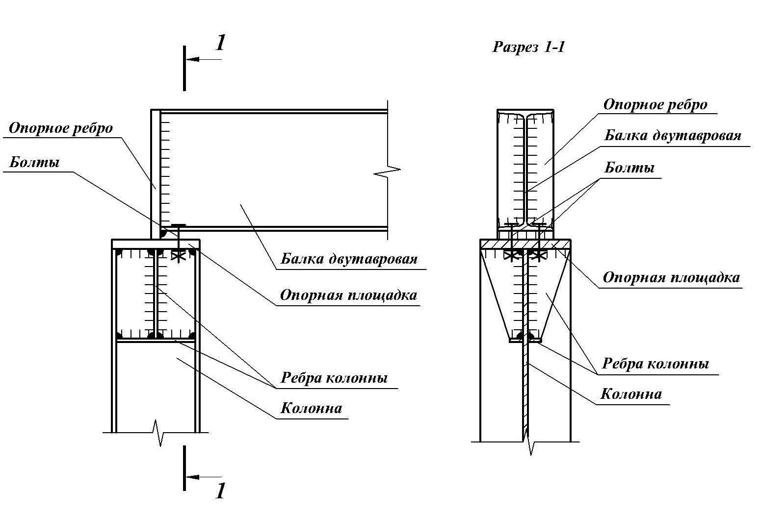
The thickness of the support platform is usually taken as 20-25 mm, the thickness of the ribs is 8-12 mm.
If there is a roof angle, the rib must be cut at the required angle and washers must be added that have a bevel for the bolt.
Supporting 2 beams on a column from above.

Similarly to the previous option, we support the beams through the rib on the head of the column.
We connect the beams together with bolts. It is not worth installing bolts from above, unless of course you want to create a rigid knot. Between the 2 ribs we install plates in order not to pull the beams together (this can load the column with a moment at the opposite end of the beam).
There is also an option to support the 2nd beams on the head of the column in the following way
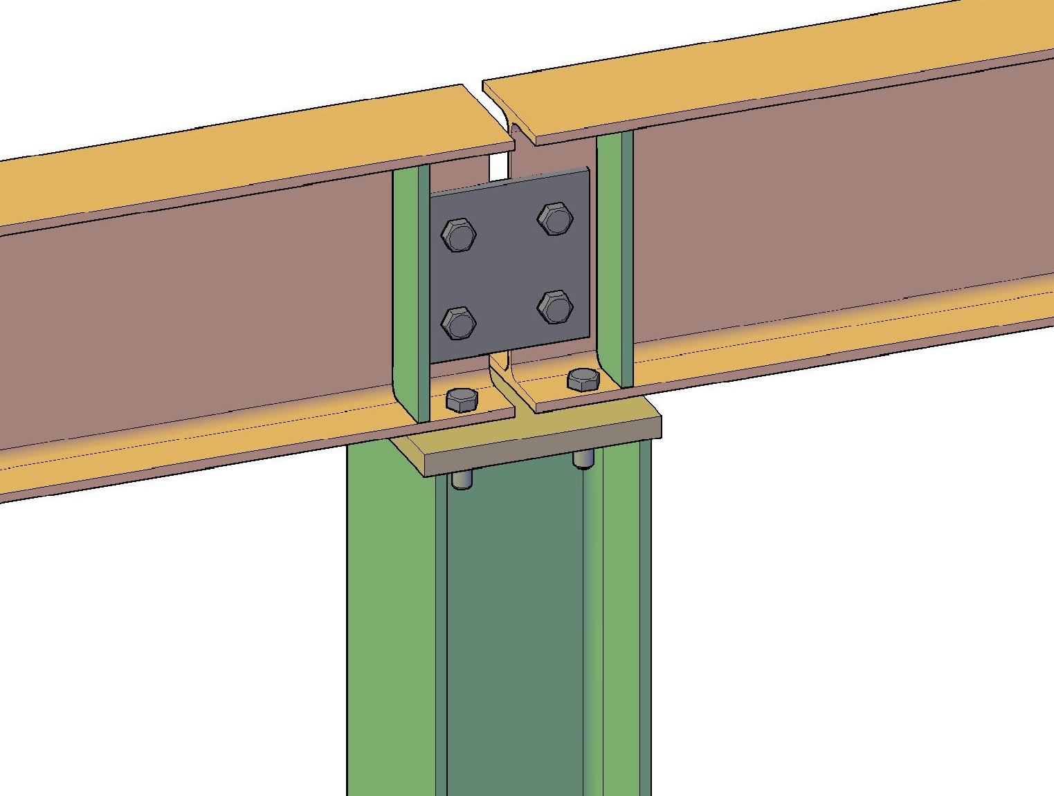
In this embodiment, the beam with the lower shelf lies on the head of the column.
To transfer the transverse force, the beam is reinforced with a rib, the rib is set so that during installation it is directly above the column flange. We connect the beams with bolts using an overlay plate (for symmetrical load transfer, it is better to use 2 plates on 2 sides). As in the previous option, there is no need to connect the beams with bolts from above, so as not to create a rigid knot.
Ribs on the column, in this case, are not needed.
Between 2 beams we leave a small gap of about 10-20 mm.

Hinged support of a beam on a column from the side
For lateral fastening, it is necessary to take into account the eccentricity in the calculations of the column.

With hinged support, the load is transferred through the support rib to the support table. The table is usually made of sheet steel or an unequal corner. The height of the support table is determined from the condition of the strength of the welds. It is advisable to weld the table on 3 sides. The width of the table is made 20-40 mm larger than the edge of the beam so that the support edge lies completely on the support table.
The diameter of the holes is made 3-4 mm larger than the diameter of the bolts so that the beam does not hang on the bolts, but lies completely on the table.
The supporting edge of the beam is calculated for collapse using the same formula as for a beam supported from above.
With hinged support, the ribs in the column are not required. A gasket approximately 5 mm thick is mounted between the support rib and the column.
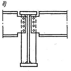
Rigid connection of a beam with a column using a bolted connection
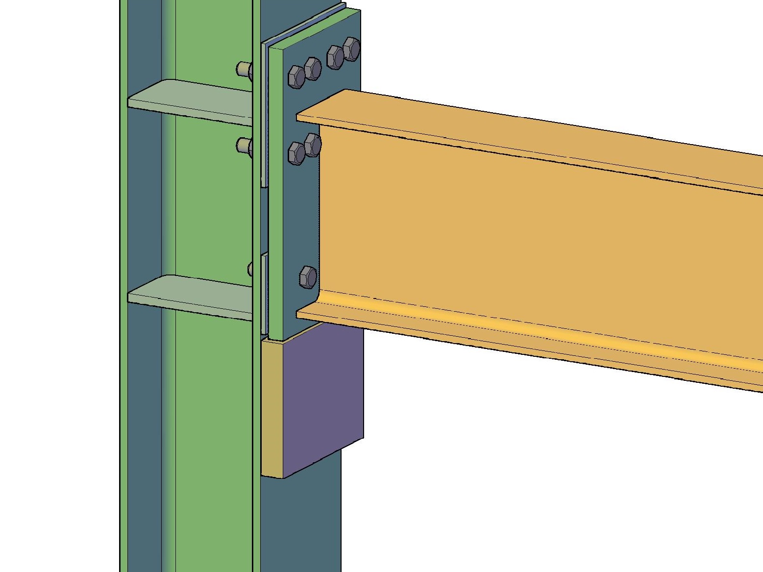
You can create a rigid connection by bolting or welding. Bolted connection is more technologically advanced - all parts are manufactured and painted at the factory, at the construction site it is only necessary to install and tighten the bolts.
In this node, the transverse force is perceived in the same way as in the hinged node using the support table. The moment is transmitted by means of bolts to the walls of the column. Between the support edge of the beam and the column, it is necessary to install steel spacers for a snug fit between the beam and the column (there should be no gap after tightening).
The number and diameters of the bolts for the upper chord must be calculated based on the moment that occurs in the embedment of the beam. Bolts are used only high-strength. It is necessary to control the tightening of the bolts.
The walls of the column are reinforced with stiffeners.

2.440-1.1 01 KM Articulated joints. Hinge Application Recommendations
2.440-1.1 02 KM Articulated joints. Floor support of beams. Nodes 1 and 2
2.440-1.1 03 KM Articulated joints. Fastening beams on the supporting corners. Node 3
2.440-1.1 04 KM Articulated joints. Fastening beams on the supporting corners. Node 4
2.440-1.1 05 KM Articulated joints. Geometrical characteristics and bearing capacity of node 4
2.440-1.1 06 KM Articulated joints. Supporting beams on ribs from channels. Node 5
2.440-1.1 07 KM Articulated joints. Supporting beams on the edge of the Taurus. Node 6
2.440-1.1 08 KM Articulated joints. Mounting beams on the support strips. Nodes 7, 7a, 8, 8a
2.440-1.1 09 KM Hinged joints. Table of geometric characteristics and bearing capacity of nodes 7, 7a
2.440-1.1 10 KM Swivel joints. Table of geometric characteristics and bearing capacity of nodes 8, 8a
2.440-1.1 11 KM Articulated joints. Fastening beams on the support strips from the corners. Node 9
2.440-1.1 12 KM Swivel joints. Supporting beams on the head of the rack, central support. Nodes 10, 11
2.440-1.1 13 KM Articulated joints. Table of geometric characteristics and bearing capacity of nodes 10, 11
2.440-1.1 14 KM Articulated joints. Fastening of beams on 2 bolts of normal accuracy (horizontal). Nodes 12, 13
2.440-1.1 15 KM Articulated joints. Fastening of beams to columns on 2 bolts of normal accuracy. Node 14
2.440-1.1 16 KM Articulated joints. Fastening of beams to columns on 3 bolts of normal accuracy. Node 15
2.440-1.1 17 KM Articulated joints. Fastening of beams to columns on 4 bolts of normal accuracy. Node 16
2.440-1.1 18 KM Articulated joints. Fastening of beams to columns on 5 bolts of normal accuracy. Node 17
2.440-1.1 19 KM Articulated joints. Fastening of beams to columns on 6 bolts of normal accuracy. Node 18
2.440-1.1 20 KM Articulated joints. Fastening of beams to columns on 7 bolts of normal accuracy. Node 19
2.440-1.1 21 KM Articulated joints. Fastening of beams to beams on 2 bolts of normal accuracy. Node 20
2.440-1.1 22 KM Articulated joints. Fastening of beams to beams on 3 bolts of normal accuracy. Node 21
2.440-1.1 23 KM Articulated joints. Fastening of beams to beams on 4 bolts of normal accuracy. Node 22
2.440-1.1 24 KM Articulated joints. Fastening of beams to beams on 5 bolts of normal accuracy. Node 23
2.440-1.1 25 KM Articulated joints. Fastening of beams to beams on 6 bolts of normal accuracy. Node 24
2.440-1.1 26 KM Articulated joints. Fastening of beams to beams on 7 bolts of normal accuracy. Node 25
2.440-1.1 27 KM Articulated joints. Fastening of beams to beams on 2 bolts of normal accuracy. Node 26
2.440-1.1 28 KM Articulated joints. Fastening of beams to beams on 3 bolts of normal accuracy. Node 27
2.440-1.1 29 KM Articulated joints. Fastening of beams to beams on 4 bolts of normal accuracy. Node 28
2.440-1.1 30 KM Articulated joints. Fastening of beams to columns on 2 bolts of normal accuracy. Node 29
2.440-1.1 31 KM Articulated joints. Fastening of beams to columns on 3 bolts of normal accuracy. Node 30
2.440-1.1 32 KM Articulated joints. Fastening of beams to columns on 4 bolts of normal accuracy. Node 31
2.440-1.1 33 KM Articulated joints. Fastening of beams to columns on 5 bolts of normal accuracy. Node 32
2.440-1.1 34 KM Articulated joints. Fastening of beams to columns on 6 bolts of normal accuracy. Node 33
2.440-1.1 35 KM Articulated joints. Fastening of beams to columns on 7 bolts of normal accuracy. Node 34
2.440-1.1 36 KM Articulated joints. Supporting beams on brick walls. Knots 35-38
2.440-1.1 37 KM Frame units. General form and node characteristics table 39
2.440-1.1 38 KM Frame units. General view and table of characteristics of node 40
2.440-1.1 39 KM Frame units. Nodes 39, 40
2.440-1.1 40 KM Frame units. General view and table of characteristics of node 41
2.440-1.1 41 KM Frame units. General view and table of characteristics of node 42
2.440-1.1 42 KM Frame units. Nodes 41, 42
2.440-1.1 43 KM Frame units. Assembly details 39-42
2.440-1.1 44 KM Frame units. Table of characteristics of details of nodes 39-42
2.440-1.1 45 KM Frame units. Support tables for crossbars in knots 39-42, 44, 45
2.440-1.1 46 KM Frame units. General view of node 43. Table of characteristics of nodes 43, 44
2.440-1.1 47 KM Frame units. General view and table of characteristics of node 44
2.440-1.1 48 KM Frame units. Nodes 43, 44. Vertical overlays along the walls of the crossbars in node 43. Table of characteristics of overlays
2.440-1.1 49 KM Frame units. Horizontal overlays along the belts of the crossbars in nodes 43, 44. Table of characteristics of the overlays
2.440-1.1 50 KM Frame units. General view and table of characteristics of node 45
2.440-1.1 51 KM Frame units. Knot 45. Horizontal lining on the belts of the crossbars. Overlay characteristics table
2.440-1.1 52 KM Frame units. Table for selection of horizontal stiffeners in columns
2.440-1.1 53 KM Frame units. Horizontal stiffeners in columns. Rib characteristics table
2.440-1.1 54 KM Frame units. Overhead stiffening ribs
2.440-1.1 55 KM Frame units. Table of bearing capacity of columns by strength
2.440-1.1 56 KM Frame units. Table of bearing capacity of crossbars by strength
Six schemes of classical constructive solutions are presented in the issue of bearing metal beams of floors on the brick walls of buildings.
● The design of buildings includes the process of designing beam floors, associated with many mathematical calculations - the calculation of field connections, the layout of the beam support nodes, the selection of sections of individual elements that are designed to ensure the operability of the nodes.
● The choice of one of the presented options should be based on the value of the support pressure under the end of the beam - i.e. support reaction is
a fundamental factor in choosing a solution. steel beams floors should not just be laid on load-bearing brick walls, but should be supported through reinforced concrete or steel distribution pads. The main tasks of these pillows include:
- equalization of pressure under the ends of the beams;
- prevention of local destruction brickwork under the supporting sections of the beams.
● The first four nodes (out of six) involve the hinged way of supporting the beams directly on the brick wall through a layer of mortar 15 mm thick. The support pressure is transmitted to the brickwork through the supporting metal plates 20 mm thick. The dimensions of the base plates are chosen in such a way that the average pressure under them - that is, on the compression area - is not greater than the calculated resistance of the brickwork on a rigid cement mortar. The load-bearing brick wall should be made of solid brick with good strength characteristics.
If the value of the support pressure exceeds 10 tons, then the required thickness of the reinforced concrete distribution cushion should already be at least 100 mm, and the cushion itself should be equipped with two reinforcing meshes. In this case, the support nodes of metal beams must be rigid and it is strictly not allowed floor beam support straight to the brick wall. Guidelines in this matter are the requirements of SNiP II-22-81 * Stone and reinforced masonry structures.
● Support node No. 1 hinged. Brick wall thickness b=380 mm. The limiting value of the support reaction R=0.6 t.
● Support node No. 2 hinged. Brick wall thickness b>380 mm. The limiting value of the support reaction R=0.7-3.0 t. 
● Support unit No. 3 hinged. Brick wall thickness b>380 mm. The limiting value of the support reaction R=3.1-5.0 t. 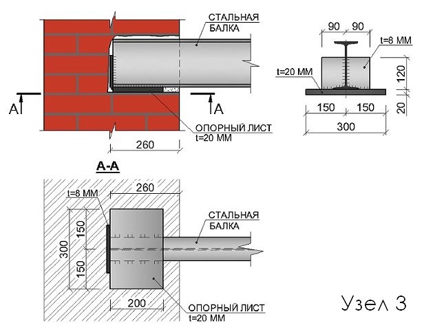
● Support unit No. 4 hinged. Brick wall thickness b>380 mm. Limiting value of the support reaction R=5.1-7.0 t. 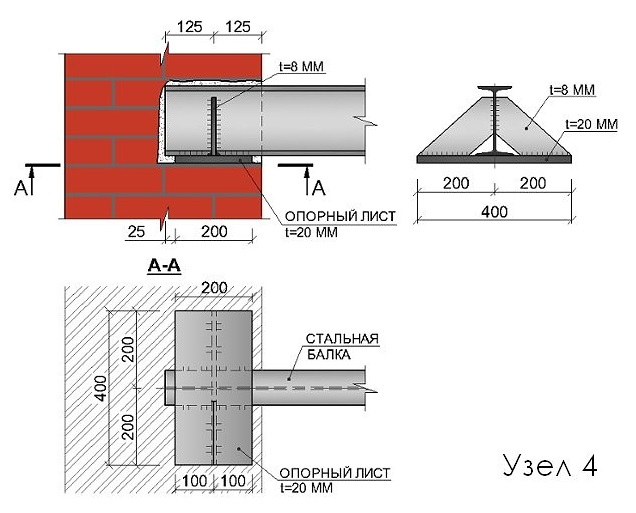
● Support node No. 5 rigid. Brick wall thickness b>380 mm. The limiting value of the support reaction R=10.1-18.0 t. 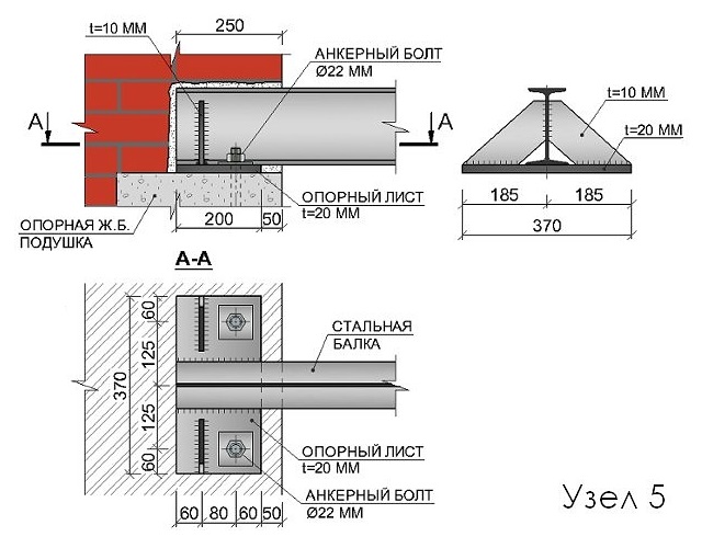
● Support node No. 6 rigid. Brick wall thickness b>380 mm. The limiting value of the support reaction R=18.1-20.0 t. 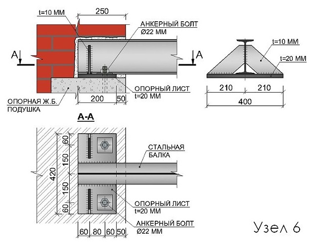
In all nodes, all friction joints elements are made on anchor bolts of accuracy class B, with strength classes 5.8 and 8.8.
In all nodes, the legs of all fillet welds should be taken according to the smallest thickness of the welded elements. Minimum values are specified in Table 38 of SNiP II-23-81* Steel structures.
● If during the operation of the building there will be any dynamic loads, then all elements and details of support nodes V without fail must be tested for endurance.
The beams are connected to steel columns by supporting them from above or by adjoining the side to the doubly. Such a connection can be either hinged, transmitting only the support reaction of the beam, or rigid, transmitting to the column, in addition to the support reaction, also the moment of pinching the beam in the column. Hinged connection is widely used in most beam structures, rigid - in the frames of multi-storey buildings. Examples of supporting beams on columns from above are shown in fig. 15.
Rice. 15. Supporting beams on columns
a, b - top
c - side
The end of the beam in the place where it rests on the support is reinforced with support ribs, assuming that the entire support reaction is transferred from the beam to the support through these stiffeners. the lower chord of the beam (Fig. 15, a), or planed to directly transfer the support pressure to the steel column (Fig. 15.6). For the correct transfer of pressure to the column (with a constructive solution according to Fig. 15, a), the center of the supporting surface of the rib must be aligned with the axis of the column flange.
The size of the supporting stiffeners is usually determined based on the collapse of the end of the rib
![]() (7.60)
(7.60)
The protruding part of the support rib (Fig. 15, b) should not exceed a< 1,5 t OP и обычно принимается 15-20 мм.
In addition to checking for collapse of the end of the support rib, the support section of the beam is also checked for stability from the plane of the beam as a conditional support rod, which includes the support ribs and part of the beam wall with a width of 0.65 in each direction in the design section area (in Fig. 15, b, and this area is shaded) and a length equal to the height of the beam web:
![]() (7.61)
(7.61)
The attachment of support ribs to the beam web by welds must be designed for the full support reaction of the beam, taking into account the maximum working length of the weld. Hinged connection of beams on the side according to fig. 15, c) in its design, work and calculation does not differ from the description of the beams from above in fig. 15, b.
11. Design and calculation of the column head.
With free pairing, beams are usually placed on top of the column, which ensures ease of installation.
In this case, the column head consists of a slab and ribs that support the slab and transfer the load to the column rod.
If the load is transferred to the column through the milled ends of the supporting ribs of the beams located close to the center of the column, then the head plate is supported from below by ribs running under the supporting ribs of the beams.
The ribs of the head are welded to the base plate and to the branches of the column with a through rod or to the wall of the column with a solid rod. The seams attaching the head rib to the slab must withstand the full pressure on the head. Check them according to the formula:
The height of the head rib is determined by the required length of the seams that transfer the load to the column rod (the length of the seams should not be more than):
The thickness of the head rib is determined from the condition of resistance to collapse under full support pressure:
Having assigned the thickness of the rib, you should check:
![]() (8.38)
(8.38)
With small wall thicknesses of the channels of the through column and the walls of a solid column, they must also be checked for a cut at the place where the ribs are attached to them. It is possible to make the wall thicker within the height of the head.
To stiffen the ribs that support base plate, and to strengthen the walls of the column rod from buckling in places where large concentrated loads are transmitted, vertical ribs that perceive the load are framed from below with horizontal ribs.
The head base plate transfers pressure from the overlying structure to the head ribs and serves to fasten the beams to the columns with mounting bolts that fix the design position of the beams.
The thickness of the base plate is adopted constructively within 20-25 mm.
With a milled column end, the pressure from the beams is transmitted through the base plate directly to the head ribs. In this case, the thickness of the seams connecting the slab with the ribs, as well as with the branches of the column, is assigned constructively.
Large bearing pressures of the beams are best transferred to the column through the ribs located above the flanges of the columns.
If the beam is attached to the column from the side, the vertical reaction is transmitted through the supporting edge of the beam to the table welded to the flanges of the column. The end of the supporting edge of the beam and the upper edge of the table are attached. The thickness of the table is taken 20-40 mm more than the thickness of the supporting edge of the beam.
It is advisable to weld the table to the column on three sides.
Welds that weld the table to the column are calculated by the formula:
The coefficient 1.3 takes into account the possible non-parallelism of the ends of the support rib of the beam and the table due to manufacturing inaccuracies, which leads to an uneven distribution of the reaction between the vertical seams.
To prevent the beam from hanging on the bolts and firmly on the support table, the support ribs of the beam are attached to the column rod with bolts, the diameter of which should be 3-4 mm less than the diameter of the holes.
Node of supporting the main beam on cap columns.