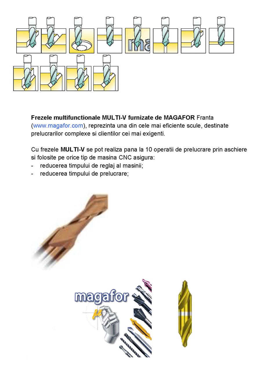
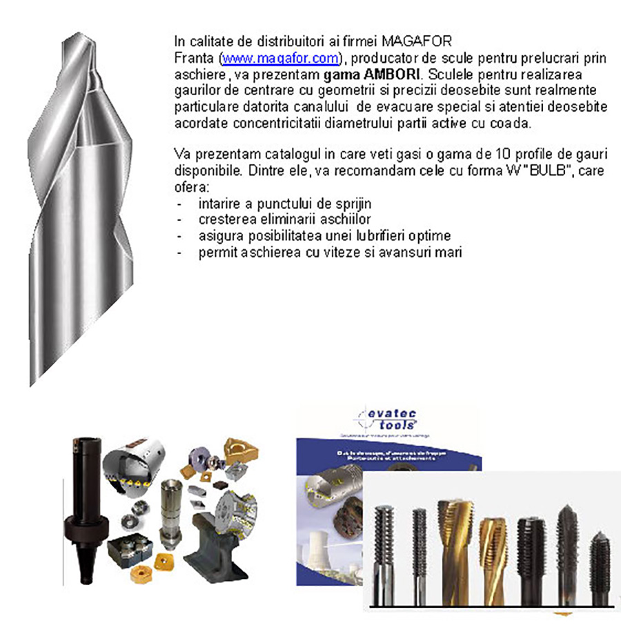
Coursework: Machining parts on lathes. Metal turning on CNC machines. Types of lathes
Most often on the Internet you can find articles about working on CNC machines for wood or plastic, nevertheless a good machine can handle aluminum. The main thing is to know how to work with it correctly.
There are a few fundamental differences between working on aluminum and working on wood or plastics that you need to keep in mind. Firstly, the limits of the optimal cutting regime for aluminum are much narrower. When going beyond the optimal mode, the cutters begin to wear out much faster, and the surface leaves much to be desired. You also need to keep in mind that aluminum and its alloys tend to clog the grooves of your cutting tool tightly. When the chips completely clog your cutter, it will stop cutting metal, and when fed, the tool will simply put pressure on the workpiece, which will lead to its breakage. Even if initially working on aluminum may seem challenging task, it can be processed on almost any CNC machine. In this article, we will consider 10 useful tips that will allow the work to be carried out correctly and safely.
The material is cut, but the lattice is also cut. Often gratings are used in grating cutting machines. Unfortunately, due to their small thickness, they quickly deteriorate and often need to be replaced. Grid adjustment With repeated grilling, the height of the grid can be finely adjusted due to inaccurate ribs so that the gap between the nozzle and the material is always in the optimum range. High working speeds and acceleration Most waterjet users are convinced that these machines are free and do not have high processing speeds.
1. Take your time.
Although the CNC machine can process a variety of metals, it is not the most suitable tool for the production of large-sized products, such as large car parts. For quality cutting, you need to work slowly, just letting the machine do its job - and in this case, a large part will be processed unreasonably long. In general, metal processing is a very serious load for the machine, so you need to correctly calculate the speed and depth of cut, the amount of feed - according to the characteristics of your machine.
However, the rate of development of waterjet technology is fast enough to test these claims. Thin and relatively soft materials such as aluminium, ceramics, etc. Can be cut much faster today than a few years ago, and so with these materials cutoff speed is often no longer just cutting technology, but only water restrictions from the control and drive system.
This makes it even possible to improve cutting efficiency, especially when using thin materials. Rigid spatial structure baths and self-supporting structure. The basic geometrical concepts of the waterjet machines are divided into essentially monolithic solutions and thus the grid bath and material are not mechanically connected to the head positioning set. Some manufacturers explain that separating the bath from the coordinating head system improves handling because vibration is not transmitted.
2. Use a calculator to calculate the spindle feed rate.
Take advantage of the cutting speed and feed calculator to optimize your settings. Do not cut "by ear", it will not lead to anything good. It is better to use calculators, which in our time are easy to find on the Internet, both in the form of sites with the necessary fields for filling and calculating online, as well as individual professionally developed software products. Ideally, you should use a calculator that will display the following indicators:
- Setting the lower limit for the minimum possible RPM. What's the point of a calculator if it keeps offering you lower RPMs than your machine allows?
- Maintain as much as possible more types cutting tools: cylindrical cutters, face, worm, end, conical, and many others;
- Take into account the bending strength of the material;
- Display wear rate warnings. When working at low speeds and elevated temperatures, it increases significantly.
- Consider chip thinning: when you make small cuts that are less than half the diameter of your tool, this will also increase tool wear.
- The ability to calculate several modes of operation of the machine in terms of power as needed.
After calculating the operating mode, you will most likely still have the problem of a discrepancy between the recommended speed, since calculators usually give very low values. The minimum speed of most machines is limited and often much higher than what is needed for cutting aluminium, but there are ways to solve this problem in other ways. The next couple of tips will show possible ways solutions to this problem.
First of all, there should be no vibration. And as they cut the head and cut the material, we need to move together. This is a monolithic version with the coordination system mounted on the tank. There is no relative movement between these elements, which increases the accuracy of processing. We can offer both solutions according to individual beliefs, but we are inclined towards a monolithic solution. The other aspect is the boom or lock, but there is no doubt that there is no doubt that the double-sided self-propelled gate is - the best solution, and even companies that use this boom end up moving away from such solutions.
3. Use of cutters with wear-resistant coating.
A good option would be to use cutters that were originally designed to work on metals at high speeds. Usually it is a tool made of carbide materials. Conventional HSS cutters, as well as cobalt cutters, can still be too slow, so you should look for a tool with a wear-resistant coating like CC AluSpeed® (TiB2 - titanium diboride). For aluminum cutters with this coating, the chips slide over the surface of the cutter without sticking and heat transfer. They cost a little more, but the productivity and quality of the product will pay for it in full. Let's say you have a conventional HSS end mill for which the recommended spindle speed is 3,000 rpm. And your machine has a minimum speed of 8,000 rpm (a very common minimum speed for CNC machines). A CC AluSpeed® coated end mill can have a recommended speed of 7,824 rpm, which is much closer to the minimum machine speed. Therefore, such a cutter, in principle, can already be safely worked. Try to find an end tool closest to the speed of your CNC machine, this will allow you to effectively process your workpieces.
Sand and water can damage the best paint, and after a few years, a paint-only car looks very old, corroded and beaten. Our machines are hot-dip galvanized before painting, which ensures deep penetration of the zinc, providing years of corrosion protection. Stainless steel finish Despite galvanization, components are particularly susceptible to tearing and damage. In such cases, we end up with a dull one that looks aesthetically pleasing even under extreme conditions.
All Water Protective Drives Waterjet machines contain water and sand that will damage drive components and linear bearings. All drives are protected from direct influence of these factors. Air bags Water machines are noisy. In particular, there is a flow of water in the air. Even this slight stretch that flows from the nozzle into the material creates a high level of noise. The process of lifting the water table lasts a dozen or more seconds and provides better operating comfort by limiting splashing.
4. Work with smaller diameter cutters
Another way to increase the RPM is to work with a small diameter cutter. Try to work with cutters with a diameter of less than 6 mm. It is important to remember that in this case, cutters should be selected from the most rigid materials, with high bending strength. The smaller the diameter, the closer we can get to 20,000 rpm. The main principle is to combine various sizes and modes of operation to get as close as possible to the regular capabilities of your machine.
Non-Threaded Cylinders - Most pressure boosters have threaded cylinders which are costly and impractical. They are often baked, which leads to the need to replace not only the cylinders, but also the components of the cooperation bodies, which leads to an increase in operating costs. In case of damage, the contacts are very cheap and easily replaced. Larger diameter cylinders Cylinders have a much thicker wall, which increases the life of the cylinder and therefore has higher fatigue.
With smaller pumps, only tubes up to 030 can be used, which directly affects performance. The machine has three working cycles. Fully automatic like roller conveyor and maintenance mode for machine installation. Thermoplastic hole drilling - an alternative to time and costs! The worn material is used to make the collar - no foreign material added.
5. Pay attention to the timely cleaning of the work area from chips
Pay special attention to chip removal. The presence of chips in the machined holes and grooves is a sure way to break the tool. And here you should not hope too much that the built-in chip removal system is good enough, and increased attention is not needed.
There can be three times fewer threaded coils in this local thickening of the material. Autonomous device for micromechanization. The displayed data also includes marking options for the 3 rotary axes. Center for trade and repair of machine tools is a dynamically developing company based on many years of experience in the field of machining and EDM. Thanks to this, we maintain high precision and workmanship. We produce components and parts not only for Polish consumers, but also for Japanese, American, German and Central Eastern European countries.
6. Pay attention to the depth of cut - deep holes are harder to clean
The difficulty of chip evacuation increases with depth of cut, so it's better to make more passes, freeing up more space and not working very deep, than trying to save a little time.
7. Don't Forget Lubrication
It is a good idea to use pressurized coolant through a spray gun to avoid both chips sticking to the cutter and overheating of the cutting tool. An extremely useful and, in general, inexpensive solution will make work much more comfortable.
The machine was maneuvered by the operator using handles and cranks. In the case of the milling machine, the part was mounted on a workbench and, using cranks, the car made the outline of the part. There have been situations where, due to minor differences in function, changes have occurred in the dimensions of the axes, and for this reason rebuttable parts have been created that either do not fit or cannot be used. There was a great loss of raw materials, labor time and, in addition, a lot of remains.
cutter with numerical control allows the processing of complex profiles and does not require tools with profiled cuts. On the machining center, the tool rotates, but the piece does not work. Axis orientation is the main defining feature of a machining center. Vertical machining centers contribute to precision and horizontal machining centers contribute to production, but these are generalizations and many machining centers have come out of these models.
8. Don't reduce the feed rate too much!
If you go too slowly, you risk going into a mode where the tool wears more than it cuts. The feed is tied to the spindle speed. It's not enough just to comply optimum speed cutting, you still need to keep the feed per tooth within the optimal limits.
As with drilling and cutting, the machine must be matched to each material to avoid possible problems. The hardness of the workpiece as well as the rotation of the cutting tool must be taken into account before starting the machining process. Machining centers are also manufactured on CNC metalworking machines, with the machining being done from a single gripper fixture. High quality requirements are ensured by the constant modernization of the car park with numerical program management. Modern quality assurance tools at the manufacturer and sub-suppliers ensure that this level of quality is passed on to the final beneficiary.

9. If the machine cannot move the spindle in XY at a fast enough speed, use cutters with fewer teeth.
When the feed rate is not sufficient for working with aluminum, it is recommended to use single and double flute cutters with wide flutes for chips. And four- or more-tooth milling cutters are not worth working on aluminum at all! The reason is that when machining aluminum, a lot of large chips are formed. The smaller the teeth, the more space between the cutting edges, and the more space for productive removal of large pieces of chips. Multi-toothed cutters are clogged with chips tightly very quickly. The next thing to consider is the so-called "radial chip thinning". If the depth of cut, i.e. the height of the area of radial contact between the cutter and the workpiece will be less than the radius of the cutter, this will cause chip thinning, and instead of cutting, friction and heating of the tool will begin, which will ultimately lead to premature wear and a high probability of breakage. The latter type of cut is a common occurrence in hobbing operations because the depth of cut is relatively small compared to the diameter of the cutter. Recommendations for selecting the maximum chip thickness are usually given in technical specifications cutting tool.
The type of table selected depends on the purpose of the machine. All machining centers are configured with tools and implements to suit each customer's requirements. Thanks to this new technology, the application of hinges on honeycomb panels is achieved 80% faster than the old method. 
In a world where environment is changing at a very fast pace, by visiting the booth you can find the optimal inspiration platform to make the production process more efficient and competitive.
10. Don't go full throttle
Now that you've learned the 9 previous tips, let's talk about power. A machine operating at its limit is more likely to destroy the cutting tool, leave an unsatisfactory surface quality, and the accuracy of the workpiece will be poor. Data on the power and rigidity of a particular machine is not always available. The rigidity of the carrier system is estimated by the magnitude of the relative displacements of the tool and workpiece under the action of cutting forces. All this depends on the magnitude of the cutting force, the intrinsic rigidity of the individual machine nodes, the contact stiffness between the machine nodes, and the order in which these nodes are located in space. In high-precision work, it is necessary to evaluate errors under the action of elastic deformations, and it is also necessary to take into account deformations of tooling, fixtures and workpieces. Elements of the technological system can be deformed in different ways with their different location and different direction of cutting forces, and if this factor is not taken into account, unacceptable errors may occur during processing. Therefore, in the manufacture of precision parts, it is necessary to carefully conduct a preliminary assessment of the elastic deformations of the technological system.
Among the topics and cars you can find out by visiting the booth. ![]()
For 23 years we have been a dynamic company with qualified personnel, which is why all our sales consultants are certified welding engineers.
The transformation is very good product to the best. A smart, fully digitized resonant system allows faster adjustments. The result is improved priming, less splash and a very stable arc.
Conclusion
Machining aluminum on CNC machines is absolutely doable on most machines. One has only to correctly decide the issue of choosing the optimal mode, taking into account all the requirements of feed and speeds, as well as a wise choice of tool and cutting parameters. And, of course, use some calculator to calculate all this, not forgetting about the features of chip formation in aluminum processing. Successful projects!The efficiency of operation of CNC machines is largely determined by their correct technological use - the rational construction of the technological process and, in particular, the choice of cutting conditions that increase the reliability and productivity of processing.
An increase in the reliability of processing when using the limiting depth of cut and feed can be achieved by eliminating technological overloads that usually occur at the moment of insertion and exit of the tool from the cutting zone. The CNC system allows you to automatically change the feed rate at these cycle transitions. Productivity and reliability are also increased by the rational choice of cutting speed.
The experience of operating CNC machines shows that the cutting speed should be chosen taking into account the features of automated technological processes. The working moves and transitions of each tool are carried out with different depth of cut, feed and speed with different directions of movement. Each tool during the period of resistance processes different surfaces of parts from the same or various materials. Each working move is performed in modes that provide a more complete use of the machine and tool. Tools are used as part of various multi-tool setups, with a smaller part of the tools being replaced when changing the workpiece, and a large part as they become dull.
These features of the technological process significantly affect the nature of wear and the choice of cutting speed.
In CNC machines, such as lathes, cutting tools work with different directions of cutting feed and different depths of cut and feed when machining a plurality of parts, which affects the rate of wear increase, and thus the time to allowable wear.
Due to the high cost of CNC machines, the use of tools with pre-setting for size and quick-change equipment, tool life periods are chosen lower than recommended by the reference literature, and machining modes are higher.
To select cutting modes on CNC machines, special reference books are used - general engineering standards for cutting modes developed for various types of cutting tools (end mills, cutters with mechanically fastened carbide inserts, etc.).
In addition, the optimized body of the device is more robust and durable than ever. 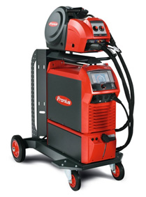
Users benefit from equipment with customization and upgrades that are highly intelligent and have extensive communications. These devices are easier to use, can be used everywhere, and have virtually unlimited effectiveness.
This type of welding equipment already meets the requirements of "Industry 0" and raises the welding technique to a new level of productivity. By increasing the processing speed, several tuning parameters can now be measured. In this way, the welding process can now be analyzed down to the smallest detail and therefore optimally controlled.
3.4.1. Selecting cutting data for turning
The depth of cut at each of the four stages of turning should provide:
- removal of processing errors and surface layer defects obtained at the previous stage of processing;
- compensation of errors that occur at the stage of workpiece processing.
In this regard, if several operations or transitions are required to machine the surface of a part, the total machining allowance is divided by the depths of cut for each of them. In this case, it is necessary to first select the depth of cut, which ensures the final obtaining of the dimensions of the part. Then sequentially choose the depth of cut for intermediate processing operations. For example, if the part needs to be machined in four steps, select the depth of cut for the fourth step first, then the depth of cut for the third and second steps. The sum of these depths determines the necessary allowance for the transition from the first transition of processing the workpiece to the fourth. The remainder of the total machining allowance must be removed in the first transition (roughing) as the depth of cut.
Feed values for each operation or transition during external longitudinal turning and end trimming are selected depending on the material being machined, the diameter of the part and the depth of cut selected in the previous step. These feeds are regulated by the material of the cutting part of the tool and the method of fastening the cutting insert. In addition, the table value of the feed is corrected taking into account the correction factors for each operation.
The values of feeds during boring are determined depending on the material being processed, the depth of cut selected at the previous stage, the section and overhang of the mandrel or cutter. These feed values are corrected with correction factors.
Selected feed for roughing and semi finishing is checked by the axial and radial components of the cutting force Px and Py, which are allowed by the strength of the machine feed mechanism.
If there is a need to obtain higher parameters of the roughness of the part, then the feed is determined by the map of standards, taking into account the required roughness and radius of the cutter tip. The selected feed value is adjusted depending on the mechanical properties of the material being processed, the tool material, the type of processing, and the use of coolant.
By comparing the feedrate of the corresponding machining operation with the roughness feedrate, the smaller of them is finally taken.
To ensure the accuracy of the shape when contouring shaped surfaces on CNC machines, it is necessary to use a correction factor for the feed k, the input of which ensures that the same processing accuracy is maintained in all sections of the shaped surface.
The feed for grooving and cutting off is selected depending on the width of the cutting part of the cutter and is limited by the grade of tool material used and the type of cutter design. In addition, the feed is adjusted depending on the mechanical properties of the material being processed, the method of fastening and the length of the workpiece, the roughness of the machined surface, and the type of processing.
The choice of feed for chamfering depends on how they are formed. If the chamfer is machined by moving the cutter in the direction of one machine coordinate, then the feed is selected in the same way as grooving. If the chamfer is processed by moving the cutter along two coordinates, then the feed is selected in the same way as for contouring.
The cutting speed during boring, turning the outer surfaces and trimming the ends is selected for the entire processing, depending on the depth of cut, feed, the material being processed, taking into account the type of cutter design and grade of tool material. In addition, the cutting speed is corrected by correction factors.
The cutting speed for grooving and parting is selected according to the recommendation and is limited by the grade of the tool material, as well as the method of fastening the insert. The cutting speed is corrected with correction factors.
Cutting conditions for boring, longitudinal external turning and trimming of ends for roughing and semi-finishing are checked by the power of the machine. The power of the machine is selected from the standard map and adjusted depending on the hardness of the material being processed. If the selected processing mode is not allowed by the power of the machine, then it is necessary to reduce the cutting speed set according to the standards.
AT general case when choosing a feed, one should be guided by the following considerations: when roughing, one should strive to select the highest possible feed. The limitations are: the power of the machine, the rigidity of the AIDS system, load bearing capacity selected cutting insert, taking into account the geometry of the front surface. Economically feasible for roughing are such modes in which a large specific metal removal is achieved due to a combination of high feed and moderate cutting speed.
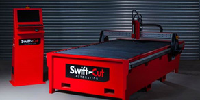
All of the latest portable cutting systems are designed to provide years of performance and efficient production. Most portable systems can be used for both beveling and straight cutting. Plasma systems are also available for various models plasma cutting sources.


It includes a series of five draw frames that incorporate the latest technology in the field. 
![]()
Represents major manufacturers of machines and tools in the sheet metal industry in Romania. 
It is an importer and distributor of semi-finished products, industrial products and accessories in stainless steel, aluminium, copper, brass, bronze and special steels.
3.4.2. Turning
The essence of turning is the formation of a cylindrical surface by a tool with one cutting edge, while, as a rule, the workpiece rotates and the cutter moves. In many ways, this traditional metalworking method is relatively easy to understand. On the other hand, this widespread process lends itself well to optimization by carefully studying the various factors that influence it.
The turning process is quite diverse in terms of the shape and materials of the workpieces, types of operations, processing conditions, requirements, cost and many other factors.
There are several basic types of turning operations, including threading, grooving, parting off, and boring, that require specially designed tools to perform effectively.
Turning can be classified as one of the simplest operations for choosing the type of tool, calculating cutting conditions and programming processing.
Turning is a combination of two movements - the rotation of the workpiece and the movement of the tool. In some cases, the workpiece remains stationary and the tool rotates around it, but the principle is the same. The tool feed can be directed along the axis of the workpiece, which means the processing of the diameter of the workpiece (Fig. 3.12). In the case when the tool moves in the transverse direction to the center of the part, the end face is trimmed to a certain length of the part. Sometimes the feed is a combination of these two movements, either in threading or in curved surfaces, which is now easily done on CNC machines with great toolpath programming capabilities.
Rice. 3.12. Turning and facing, as examples of axial and radial movement of the tool.
The optimization of the turning process takes place not only in the direction of increasing the rate of metal removal, but also in order to increase the controllability of the process, which ultimately affects the quality of the machined parts and the reliability of the entire work. The separation of chips from the workpiece occurs in accordance with the selected cutting parameters, which determine its shape and size.
When processing metal by cutting, it is necessary not only to obtain a part of a certain shape, size and the required quality of the machined surface, but also to ensure the formation of short, easily transportable chips (Fig. 3.13). This is especially important at high processing conditions on modern CNC machines, when a large amount of chips is formed per unit time and it is necessary to ensure non-stop operation of the equipment, operator safety and prevent damage to the workpiece. Chip shape can vary depending on the material being machined, ranging from long, twisted chips from tough materials to loose chips from brittle materials.
Rice. 3.13. Chip shape typical for processing: a) finishing; b) draft.
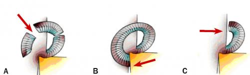
Chip separation perpendicular to the surface to be machined occurs when the direction of feed and the axis of rotation of the workpiece forms a right angle with the main cutting edge. This simple type of processing is found only in some operations, such as cutting off and plunge. Most turning operations occur in conditions where the main cutting edge is located at a certain angle to the cutting direction. This change in geometric parameters entails a change in the direction of chip flow. Most often, the chips are in the form of commas or helical spirals, in contrast to the chips formed during parting, which are in the form of a cylindrical spiral.
Chip formation is greatly influenced by the entering angle and tool nose radius. As the entering angle decreases, the chip thickness decreases and its width increases. The direction of chip flow also changes, usually for the better, as the helix pitch increases. The shape and direction of the chip flow also change depending on the depth of cut and the radius of the cutting edge. With a small ratio of depth of cut and radius at the top, only the radius part of the insert will participate in the cutting and a spiral chip will form. A large depth of cut will reduce the influence of the nose radius and increase the effect of the entering angle on the direction of spiral chip flow. The amount of feed also affects the width of the cross-section of the chip and the direction of the descent.
A chip that is square in cross section usually indicates an excessive load on the cutting edge, and wide chips will form into unwanted long ribbons (Fig. 3.14). As the chip curl becomes smaller and thicker, the length of contact between the chip and tool increases, with increasing pressure and strain. Excessive chip thickness has a negative effect on the machining process.

When the feed is set above the allowable value for which the geometry of the rake face is designed, the chips will pass over the chip breaker groove and abut against the ledges. As a result, cutting will be performed with negative geometry, instead of positive, with unstable chip formation.
Rice. 3.14. The working area of the insert, determined by the combination of feed and depth of cut that provides satisfactory chip breaking.
Finishing inserts working in the area immediately adjacent to the cutting edge will have a chip-breaking groove and ledges concentrated at the tip of the insert, while roughing inserts will have chip-breaking geometry elements distributed over most of the front surface.
Some inserts are able to provide satisfactory chip formation in a fairly wide operating range due to a certain combination of chipbreakers, which are the transition from the radius part of the insert to the wide one.
The chip breaking method (Fig. 3.15) depends in part on the geometry of the insert and tool and on the cutting conditions. Any type of chip breaking can lead to undesirable consequences, but they can be avoided by choosing the appropriate geometry and operating parameters. In case of self-breaking of chips, with insufficient tool life, it is recommended to use a geometry with a more open chipbreaker. When the chip breaks against the flank of the tool, it can cause the shearing chip to damage the cutting edge on the other side of the insert, and an insert with a different rake geometry (harder or with a more open chipbreaker) should be selected. An alternative solution could be to change the pitch.
Rice. 3.15. Chip breaking methods:
A - chips break in the process of cutting itself, for example, when machining cast iron;
B - chips break from contact with the tool;
C-chip breaks on contact with the workpiece.
If the chip breaks against the workpiece, when machining at a high feed rate, insufficient chip spreading may occur and a smaller entering angle should be selected.
Short-chipping materials need a small or no chipbreaker, while sticky materials simply require a chip-breaking insert to deform the chip during cutting. At the initial moment of cutting, as a rule, there is no chip breaking. The chipbreaker is inherently a built-in obstacle to the flow of chips (Fig. 16). In such a rough form, it can have a negative impact on the processing process.
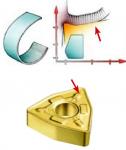
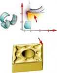

Fig.3.16. Chip breakers and their corresponding chip breaking diagrams.
In the process of improving the geometry of interchangeable plates, various forms of chipbreakers appeared, first obtained by grinding, and later formed by pressing and subsequent sintering of the plate. A modern indexable insert is a complex combination of angles, planes and radii to provide optimum chip control during the cutting process.
Most inserts provide a positive rake angle when mounted in a holder with a slightly negative rake angle, which facilitates chip formation and promotes a positive cutting process. Negative chamfers, having different lengths, depending on the working area of the geometry, are designed to harden the cutting edge.
Chip control is one of the critical factors especially when turning and drilling. When milling, the cutting process is interrupted and the chips naturally break into pieces. When drilling and boring, chip control is essential due to the limited space inside the hole being machined. In the process of high-performance drilling, it is necessary to ensure the formation of chips of a strictly defined shape in order to effectively remove it from the cutting zone, the accumulation of chips in which can lead to immediate tool breakage.
The diagram of satisfactory chip breaking for the selected insert geometry (based on the recommended values for feeds and depths of cut) and the tool material of the insert determine its application (Fig. 3.17). The modern range of inserts includes cutting geometries designed to handle most of the existing materials. Geometries are specialized for finishing, semi-finishing and roughing operations, as well as for heavy rough turning.
Rice. 3.17. The area of satisfactory chip breaking is typical for rough (a) and finishing (b) inserts.
Thus, chip control is achieved through a combination of insert geometry and machining conditions.
The workpiece rotates on the machine with a certain spindle speed (n), i.e. with a certain number of revolutions per minute. The spindle speed is directly correlated through the diameter of the surface to be machined with the cutting speed Vc, measured in m / min (Fig. 3.18). This is the speed at which the cutting edge moves across the surface of the workpiece.
Fig.3.18. Basic cutting parameters and tool elements that determine the turning operation.
The cutting speed is constant only as long as the spindle speed or the diameter being machined remain unchanged. When facing, for example, when the tool feed is directed towards the center of the workpiece, the cutting speed will gradually change at a constant spindle speed. On modern CNC machines, in order to maintain a constant cutting speed, it is possible to change the spindle speed accordingly. But when machining very small diameters and as close as possible to the axis of the workpiece, this compensation will not be feasible, since the speed range of the machine is limited. In the event that the workpiece has differences in diameters, a conical or curved surface, the cutting speed must be assigned taking into account these changes.
The feed (fn) in mm/rev is the linear movement of the tool in one revolution of the part. The feed has a great influence on the quality of the machined surface, as well as on the chip formation process. It determines not only the thickness of the chip, but also its shape, in accordance with the geometry of the insert.
The depth of cut (ap) is half the difference between the machined diameter and the machined diameter, expressed in mm. The depth of cut is always measured in the direction perpendicular to the tool feed direction.
The cutting edge approaches the part at a certain angle, which is called the entering angle (kr). It is measured between the projection of the main cutting edge on the main plane and the direction of feed and is an important value that determines the choice of a turning tool. It affects chip formation, the direction of cutting forces, the length of contact between the cutting edge and the workpiece, and the ability of the tool to perform certain types of processing. The entering angle usually varies from 45 to 95 degrees, but for profiling, tools with large entering angles can also be used.
The entering angle is chosen in such a way that the tool is able to process in several directions. This provides him with versatility and, as a result, a reduction in the number of necessary tools. Another option would be to choose a tool with a higher point angle to increase the strength of the cutting edge by distributing the pressure over a longer edge length. This adds strength to the tool at the beginning and end of the cut, and also contributes to a balanced distribution of forces in the process.
3.4.3. Milling
Milling is the cutting of material with a tool that has a main movement of rotation and at least one feed movement. Milling cutters are usually multi-blade tools. Milling - effective method machining, in which each of the cutting edges of the cutter removes the same amount of material, limited by the ability to form and evacuate chips. Most often, milling is used for processing flat surfaces (Fig. 3.19). But the role of milling cutters in the processing of complex curved surfaces on machining centers and multi-purpose machines is also rapidly growing.
The cutter usually cuts in one or more directions: (A) radial, (B) peripheral, and (C) axial (Figure 3.20). Each milling method can be decomposed into these three basic movements combined with the rotation of the cutter.
In face milling, both the periphery and the end face of the tool are involved in the work. The cutter rotates around a vertical axis in a plane perpendicular to the table feed direction.
Cutters mainly work with the peripheral part of the cutting edges. In this case, the cutter rotates around an axis parallel to the plane of the part.
In plunge milling, the end part of the cutting edge or the end of the end tool is involved in the work. The feed is directed to the axis of the cutter, the processing is similar to the process of drilling along.
Fig.3.19. The main types of milling operations in terms of the shape of the surface to be machined and the method of moving the tool: 1-face milling; 2- milling ledges; 3-profile milling; 4- pocket milling; 5- milling grooves; 6- milling of surfaces of revolution; 7- thread milling; 8- segment; 9- milling with high feeds; 10- plunger milling; 11 - milling with plunge; 12- helical interpolation; 13- circular interpolation; 14 - trochoidal milling.


Rice. 3.20. Cutter movement directions: A-radial, B-peripheral, C-axial
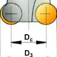
When preparing a milling operation, it is necessary to keep in mind the following parameters of the cutter. The nominal diameter of the cutter (Dc), the maximum diameter (Dc2 or D3), the effective diameter (De), used to determine the cutting speed (Fig. 3.21).
The cutting speed vc, m/min is the circumferential speed of the cutting edges of the cutter. This value determines the processing efficiency and lies within the limits recommended for each tool material.
The spindle speed n, mm / rev, is equal to the number of revolutions of the cutter per minute. Calculated in accordance with the recommended cutting speed for this type of machining.

Rice. 3.21. Geometric parameters of the cutter.
Feed per tooth fz, mm/tooth (Fig. 3.22), is used to calculate the minute feed. This is the distance between the paths of two adjacent teeth, measured in the feed direction. Since milling cutters are multi-tooth tools, it is necessary to know the thickness of the cut layer per tooth. The feed per tooth is calculated based on the maximum recommended chip thickness.
The number of cutter teeth zn can be different and affects the amount of minute feed. The choice of the number of teeth is determined by the material being processed, the milling width, the processing conditions, the power of the equipment and the required surface quality. Also, when choosing the number of teeth, it is necessary to calculate the effective number of teeth zc, i.e. number of teeth simultaneously in cut.
Feed per revolution fn (Fig. 3.22), mm/rev, is often the defining limiting parameter for finishing. It is equal to the relative displacement of the cutter and the workpiece in one revolution of the cutter.
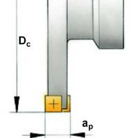
Depth of cut ap (Fig. 3.22), mm - this is the distance between the machined and unmachined surfaces, measured along the axis of the cutter.
Milling width ae (Fig. 3.22), mm - this is the value of the cut allowance, measured in the radial direction, or the width of the contact between the workpiece and the tool.

Rice. 3.22. Geometric parameters of milling.
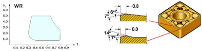
The main geometrical parameter of cutters is the leading angle kr. It is measured between the peripheral cutting edge and the face plane of the cutter and determines the direction of the cutting forces and the thickness of the cut chips. The choice of insert geometry is conditionally simplified to three areas that differ in the nature of cutting: light geometry - L (sharp cutting edge with positive angles, stable cutting process, low feeds, low power consumption, low cutting forces), medium geometry - M (universal positive geometry. , medium feeds) and heavy geometry - H (highest reliability of the cutting edge, large feeds) (Fig. 3.23).
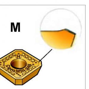
Rice. 3.23. Insert Geometry Types: Light Geometry -L, Medium Geometry -M, Heavy Geometry -H
3.4.4. drilling
Drilling is the process of making cylindrical holes with a metal cutting tool. Drilling usually precedes operations such as boring or reaming. Common to all these operations is the combination of rotational and translational motion of the tool. There is a big difference between drilling shallow holes and deep holes, for which special techniques have been developed to drill a hole many times the diameter of the tool.
With the development of short hole tools, the sequence of the drilling process and preparation for it are undergoing significant changes. Modern instrument allows drilling into solid material and does not require pre-centering holes. Achieved high quality surface and, often, there is no need for subsequent finishing of the hole.
In some ways, drilling can be compared to turning and milling operations, but drilling places more emphasis on chip evacuation. Machining in a limited hole space imposes certain requirements in terms of chip control. Most of the parts have shallow holes, so it is necessary to increase the speed of their processing, along with improving the quality and degree of processing reliability.
Drilling in solid material is one of the most common methods for making a hole of a given diameter in one operation (Fig. 3.24, a).
Trepan drilling is mainly used for large diameter holes because it does not require the same amount of power as drilling solid material. Trepanning drills do not turn all the material of the hole into chips, but leave the core of the hole intact and, therefore, are intended only for processing through holes (Fig. 3.24, b).

Rice. 3.24. Hole processing: a - drilling, b - trepanning drilling, c - boring, d - reaming.
Boring is the process of increasing the diameter of a hole with a specially shaped tool (Fig. 3.24, c).
Reaming is a process that uses a multi- or single-edged tool to improve the accuracy of the shape, hole size and reduce surface roughness (Fig. 3.24, d).
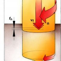
Cutting modes during drilling are set by such parameters as cutting speed, feed per revolution, feed rate or minute feed (Fig. 3.25).
The cutting speed (vc) is expressed in m/min and defines the speed at the periphery of the drill. For one revolution of the drill, a point on its periphery describes a circle of length n x Dc, where Dc is the diameter of the tool. The cutting speed changes along the cutting edge from a maximum at the periphery to zero at the drill axis. The recommended speed values refer to the speed at the periphery of the drill.
Feed per revolution (rn), measured in mm/rev, determines the amount of axial movement of the tool in one revolution and is used to calculate the axial feed rate of the drill.
Rice. 3.25. Basic cutting parameters for drilling.
The feed rate or minute feed (vf), measured in mm/min, is the feed of the tool in relation to the path it has traveled per unit of time. Another name for this value is machine feed or table feed. The speed at which the drill penetrates the workpiece is equal to the feed per revolution multiplied by the spindle speed.
Holes are either machined in solid material or finished already existing. Most parts have at least one hole and, depending on its functional purpose, there are a number of processing restrictions. The main factors characterizing the drilling operation:
hole diameter
hole depth
precision and surface quality
processed material
processing conditions
processing reliability
performance
The formation of chips with a shape and size that allows them to be easily removed from the hole is a top priority when considering any drilling operation (Fig. 3.26). Without satisfactory chip evacuation, the drill will not work due to chip flute clogging and clogging of the drill inside the hole. High-performance hole-making with modern drills is only possible if chips are easily evacuated through the use of a sufficient amount of coolant.
Most short drills have two flutes for chip evacuation. Modern equipment and tools make it possible to supply coolant through internal channels in the drill, through which it enters directly into the cutting zone, reducing the effect of friction forces and flushing chips out of the hole.
Rice. 3.26. Chip formation and evacuation, coolant supply.
Chip formation depends on the type of material being machined, tool geometry, cutting conditions and, to some extent, on the selected coolant. Usually small chips are formed when the feed is increased and/or the cutting speed is decreased. The length and shape of the chips are considered satisfactory if they allow you to reliably remove them from the hole.
Since the cutting speed decreases from the periphery to the center, the drill tip will not participate in the cut. At the top of the drill, the rake angle is negative and the cutting speed is zero, which means that it will simply push the material, which will entail the appearance of plastic deformation. In turn, this will lead to an increase in the axial cutting force. If the equipment does not have sufficient power and rigidity, spindle runout occurs and the hole shape can be oval as a result.
The use of modern drills with indexable inserts allows processing at high speeds and large volumes of chips that are washed out of the hole by coolant flows supplied under a certain pressure through internal channels. The required pressure (MPa) and volume (l/min) of coolant depends on the hole diameter, as well as on the machining conditions and type of workpiece material.
With internal coolant supply for a rotating drill, its pressure must be higher compared to a non-rotating drill due to the effect of centrifugal force. In this case, it is recommended to compensate for the lack of pressure with an additional volume of liquid. Certain pressure losses during passage through the pipelines must also be taken into account for a non-rotating drill and with external coolant.
The coolant pressure and flow should be checked, the latter should not be less than the recommended value, and the coolant reservoir should contain a sufficient amount of fluid. The coolant flow is checked at the exit of the drill, i.e. where its value must be provided. Minimum coolant flow and pressure are recommended according to drill type and diameter.
To select a drill, you must:
1. Determine the diameter, depth and requirements for the quality of the surface of the hole (taking into account the issues of reliability of processing).
2. Select the type of drill (choose a roughing or finishing drill according to the material to be machined and hole quality requirements, and provide the most economical machining).
3. Select grade and geometry (when using drills with indexable inserts, inserts must be selected separately, according to the drill diameter, geometry and grade intended for processing this material; for solid drills and drills with brazed carbide, it is sufficient to select a grade of alloy).
3. Select the type of shank (choose the type that is suitable for the equipment used).


