How many kg can withstand 1 I-beam. The weight of the I-beam is an important factor in the bearing capacity
01.10.2010, 11:47
calculation:
1) beam 200 * 200 * 6000 through 0.5M = 22 tr (deflection 20 mm)
2) I-beam 20B c / o 1.2m = 27 tr. (deflection 20 mm)
By weight 1) -90 kg timber, 2) - 120 kg beam
In theory, the solutions are very similar. Interested in practice, which is better?
Green cat
01.10.2010, 11:55
Bar.
You should not do any iron at all bearing structures for in case of fire, wood holds out to the last, but iron is cracked and ready.
01.10.2010, 15:55
The temperature at which the deformation of the I-beam will go is incompatible with life. Especially if from below it will all be sheathed with drywall.
If you still decide to make wood, then I advise 200x60x6000 in increments of 600 mm.
01.10.2010, 16:55
"hryas and ready" - but it won't matter anyway)))
It can deform in one place and fly to another, where there are still conditions for life ... :) but in general you are right.
+Wood itself will sustain combustion, but iron will not...
Green cat
01.10.2010, 17:41
The temperature at which the deformation of the I-beam will go is incompatible with life.
Not properly.
It's one thing when it's on its own, and another thing when it's under load.
Until recently, it was generally forbidden to use meth as rafters. profile, now I'm doing it with might and main.
I advise 200x60x6000 with a step of 600 mm
It will be too small, too small - we look at the caculator.
01.10.2010, 20:32
In my room, the span turned out to be 5.7 meters, the overlap between the 1st and 2nd floors. I chose an I-beam 20B after 1.3 meters, it seems that according to the calculation, the I-beam was stronger than wood. It is worth considering that a tree can be found 6.5 meters long, and the length of an I-beam is 11.7 meters or 12 meters (to cover a span of 6 meters, you need at least 15 cm per side). It would have been better to lay the plates, but I did not succeed. The difference between a tree and an I-beam was somewhere around 10-12%. When laying the walls, I installed 3 cm foam plastic between the cutout in the gas block and the I-beam.
As for the fire, you need to protect yourself.
02.10.2010, 00:47
And I put a 5.8 meter reinforced concrete slab on a 6 m span and don’t think about anything else. Doesn't burn, doesn't melt, doesn't bend...
02.10.2010, 09:00
Thanks to everyone, I still lean towards an I-beam, since it is stronger, I want to put internal walls of 100 cm foam block on the ceiling. (although it was probably possible to put 2 beams under the wall)
then wawan001 span 6M is along the axes of the walls, that is, there will be 15 cm on each side of the support.
then the Cat, I suppose if you fill up a non-combustible insulation ala expanded clay, then there will be nothing to burn there at all (a foam block house).
And another question, if you overlap with an I-beam, is it possible to use a wooden, say, 50-ku fixed to the side walls instead of the extreme beams ??
02.10.2010, 18:30
There is another option.
02.10.2010, 19:12
There is another option.
Doing load-bearing beam(albeit from an I-beam), on which you lay simple wooden beams overlap. It will come out much cheaper.
I-beams will need one or two, but powerful. The price will still come out cheaper.
I did it myself
02.10.2010, 20:01
dengt, this idea came to my mind from the point of view of the manufacturability of the device in the future of floors, if wooden floors install inside the I-beam, and make a counter-lattice on top (beams according to the calculation). The distance from the edge of the beam to the I-beam is 40 cm - reliably. Indeed, according to calculations on the extreme beams, the load is less than 2 times than on the neighboring one, you can put a 150x200 beam or take 2 pieces of 50x200 boards and install pieces of the board of the same size 1.5 meters long between them, and 50 I think is flimsy, although if the wall can pull and it will be fine. If you are sure about the fasteners, then probably yes.
04.10.2010, 05:57
I blocked the span with a 5 m beam 150 * 150 folded in half and tied with studs, i.e. it turned out a beam 150 * 300. It turned out pretty tough, but I would still make it out of concrete if I had the opportunity :(
05.10.2010, 09:32
[
i did it myself
span 11 by 6, divided into three parts by two I-beams and laid wooden beams, and in order not to increase the thickness of the ceiling, he laid them inside the brand. I pre-welded the corners to the brand and fastened the beams to the bolts.
As I understand it, I-beams were 6 meters long?
here already a minimum of 25B2 is needed, this is a 5 cm thicker overlay, it seems not fatal.
As for fixing the side beams to the walls, I am worried that all the other beams will sag and the outer ones will not, then the slab will sag with a “bubble”? what will it come to?
05.10.2010, 10:11
I-beam 6-gauge 20B1 - two pieces across the length, it turned out 3 zones, two with the support of beams of one side on the wall, and the second on an I-beam, and one zone with beams sandwiched between the I-beams. I did not notice any deflection, an I-beam does not go at such a length.
06.10.2010, 13:06
06.10.2010, 13:47
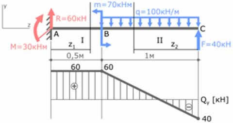
depending on how to load, if according to the theory 400 kg / m, then in your case 20B1 will bend by 77 mm
I wonder how you calculated it?
The technical characteristics of a metal profile are necessary in order to use them correctly in construction, because despite the wide variety of applications, the essence remains the same - to create a reliable supporting structure. It allows you to transform the architecture of buildings:
- increases the width of the spans of buildings;
- significantly, by about 35%, to reduce the mass of supporting structures;
- significantly increase the profitability of projects.
Speaking about the advantages of the design, it is impossible not to note the disadvantages, although there are few of them. The main ones are
- the need to use additional reinforcement when creating stiffeners;
- quite significant labor costs that are needed for its manufacture.
However, it should be noted that, on the other hand, additional stiffeners make it possible:
- reduce the overall metal consumption of welded metal structures, as they significantly reduce the wall thickness. Thus, it is possible to reduce its cost, but completely preserve the mechanical characteristics;
- in addition, the lightweight construction is also economical in terms of foundation construction, since after reducing the total mass, it is possible to use the foundation for BMZ (prefabricated buildings).
To find an I-beam suitable for specific case, some calculations are required. Usually tables are used for this. online calculators. They are based on the given two parameters: the distance from one wall to another and the future load on the building structure.
Strength I-beam defined by parameters such as:
- length,
- fastening method,
- the form,
- cross-sectional area.
Products with the letter "H" in cross section have become more widespread.
The rigidity of the metal structure of an I-beam is 30 times higher than the rigidity of a square profile, and the strength, respectively, is 7 times.
The length of this metal structure can be different, for example, in the case of GOST 8239-89 it is 4–12 meters, that is, depending on the assortment, the dimensions and weight of an I-beam differ. In addition to length, the value of weight is determined by the thickness of the metal and the dimensions of the faces. Therefore, to perform various calculations, the concept of "weight of a meter of an I-beam" was introduced. .
When buying a welded structure, a strength calculation is required, and for a specific use, a deflection calculation is also required. Proper calculation of the load on the I-beam will ensure the stability of the structure to design impacts, that is, the ability to perceive them without destruction.
Self-weight load
To determine, if necessary, the weight of an I-beam, use special tables where its characteristics are described, for example, dimensions, steel grade, etc. The table shows the theoretical mass of 1 m of the profile.
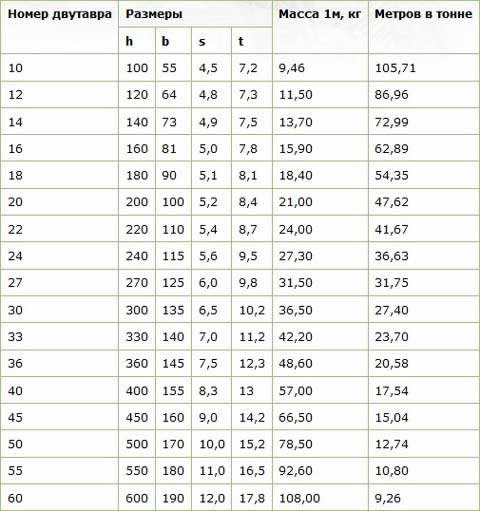
beam I-beam dimensions and weight (GOST 8239-89)
I-beam calculation example
Suppose you need to calculate the weight of an I-beam No. 12 with a length of 3 meters. According to the table, the conditional mass of a running meter of this profile is 11.50 kg. If we multiply the obtained values, we get the value of the total mass - 34.5 kg.
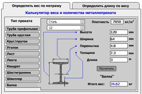
More precisely, the value of the weight of a welded metal structure can be calculated using special online calculators.
In the calculator, select the appropriate I-beam number and enter the required footage. As you can see, the value obtained is more than that calculated by us by 0.12 kg.
Load bearing capacity
Among all types of beams, the I-beam has the greatest strength, moreover, it is resistant to temperature changes. Permissible load on an I-beam it is indicated on the marking as a size. The larger the number indicated in its name, the greater the load the beam can take.
Any calculation assumes an initial knowledge of the dimensions of a rolled or welded profile, its length and width. Let's clarify the meaning of the width value using the example of the most popular beam support - the column.
Suppose that in the section of the column there is a square with a side of 510 mm, then it will be possible to support a profile on it, for which the width cannot exceed 460 mm. This is due to the fact that the I-beam will have to be welded to a reinforced concrete pad, and a margin of at least 40 mm will be needed for welding seams.
After determining the width, they proceed to the selection of the profile and the calculation of the load acting on the profile. It is a combination of impacts from the overlap, as well as impacts of a temporary and permanent nature.
The load, expressing the value of the standard load, is collected for a length of 1 m of the profile.
But the calculation bearing capacity I-beam involves taking into account another impact. To obtain the design load, the calculated standard action is multiplied by the so-called load factor. It remains to add the already calculated mass of the product to the result and find its moment of resistance.
The data obtained is sufficient to select the profile required for the manufacture of the welded profile from the assortment. As a rule, taking into account the deflection of the structure, it is recommended to choose a profile two orders of magnitude higher.
A welded metal structure should use approximately 70-80% of the maximum allowable deflection.
Gain
If the bearing capacity of the I-beam is insufficient, then it becomes necessary to strengthen it. For various elements of a welded structure, this issue is solved in different ways.
For example, for elements that perceive loads such as tension, compression or bending, they use this reinforcement option: they increase the cross section, in other words, increase rigidity, say, by welding additional parts.
Theoretically, this is one of the best options amplification, however, when it is implemented, it is not always possible to obtain the required result. The fact is that the elements in the process of welding heat up, and this entails a decrease in the bearing capacity.
To what extent such a decrease can be expected depends on the size of the I-beam and the mode and direction of welding. If for longitudinal seams the maximum reduction is within 15%, then for seams in the transverse direction it can reach 40%.
Therefore, when reinforcing an I-beam under load, it is strictly forbidden to apply seams in the direction transverse to the element.
It has been calculated and experimentally proved that the optimal result of strengthening under load can be obtained at a maximum stress of 0.8 R y , that is, 80% of the calculated resistance of the steel that was used to manufacture the I-beam.
Beam 20. Application. Kinds. I-beam calculation.
I-beam- rental, having a section of the letter H and meaning with Latin- “two-horned” on both sides (“taurus” - bull). The distance between the shelves is called the height, for an I-beam of the 20th, the height is about 200 mm or 20 cm.
I-beam 20 is most common in use by builders and installers, primarily when installing frames with large spans in buildings, to redistribute the load from the ceilings to the supporting structures. It is used for bridge construction, cranes, automobiles, pipelines, aircraft hangars, railway construction, etc. The 20th profile is produced according to 8239 GOST steel I-beams, state standard 26020-83, I-beam gost 19425-74 and specifications STO ASChM 20-93.
I-beam The 20th is subdivided according to STO ASCHM 20 into a normal beam 20B with parallel edges of the shelves, a wide-shelf beam 20Sh and 20K - for columns. I-beam STO ASCHM 20-93 with a height of 20 cm has the edges of the shelves, which are parallel. STO I-beam produced by NLMK, which developed this standard. This standard also produces beam 09G2S, which is also subdivided into a normal beam, column and wide-shelf. Low-alloy steel rolled metal can be used both at very low temperatures and at high temperatures without being deformed.
I-beam steel 20B1 has a mass of a meter - 21.3 kilograms. The mass of 20Sh1 is 30.6 kg per meter, the weight of the column beam 20K1 is 41.4 kg, I-beam weight 20K2 - 49.9 kg. Parameters of an I-beam 20B1: height (h) - 200 mm, shelf width (b) - 100 mm, wall thickness (s) - 5.5 mm, shelf thickness (t) - 8.0 mm. The wide-shelf 20th profile 20Sh1 has the following characteristics: h - 194 mm, b - 150 mm, s - 6 mm, t - 9 mm. column beam 20K1 has h 196 mm, b walls - 199 mm, s walls - 6.5 mm, t shelves - 10.0 mm.
Beam 20 according to the standard 19425 can be monorail (indicated by the letter M) and special. (referred to as C). This GOST applies to hot-rolled I-beams with flanges having an inclination of the inner surface of the flanges. An I-beam monorail, known as a girder crane, is designed  for crane tracks, as a load-bearing bridge in gantry or overhead cranes, as a rail beam. Such a product is characterized by high strength and is able to withstand heavy loads, pressure, twisting. A special beam is applicable in the shaft of structures that provide the movement of lifting shafts, that is, for reinforcing mine shafts, as well as in the construction of stairs and laying engineering communications, fastening drainage systems.
Special profile 20C has the following parameters - I-beam dimensions: height - 200mm, shelf width - 100mm, wall thickness - 7mm, shelf thickness - 11.4mm. The mass of 1 m of such an I-beam is 27.9 kg. The weight of a running meter of a beam in the tables is theoretical, it is needed in order to independently calculate the weight of an entire beam or required amount meters and I-beam pieces. So, if the beam 20 in the warehouse of the metal trading company has a length of 12 m, then to find out the weight of one whip, you need I-beam weight 1 meter 27.9 times 12m. Knowing the total number of meters of the beam, you can easily calculate the total weight of the required rolled metal. In practice, it is best to find out by asking the managers of JSC Metallotorg, who, in addition, will tell you the cost of the metal, the I-beam price per meter, and issue an invoice to I-beam to buy, and will solve all current issues on loading and delivery.
I-beam GOST 8239 89- on the range of I-beams, which has a difference - slope internal surfaces shelves Such a beam with a distance between the shelves of 200 mm has a width of these shelves - 100 mm, a metal thickness in the middle of the height - 5.2 mm, a shelf thickness of 8.4 mm.
What I-beam better? Hot rolled I-beam or welded?
To choose between hot-rolled beam 20 and a welded profile with similar parameters, calculate the moment of resistance. To do this, take into account the load on the floor, continuous and short-term load, use tabular data - the strength factor and the allowable deflection for load-bearing structures.


