Steel beam deflection online. Calculation of wooden floor beams: online calculator, calculation principles. Drawing up a design diagram of a beam
Beam - an element in engineering, which is a rod that is loaded by forces acting in a direction perpendicular to the rod. The activities of engineers often include the need to calculate the deflection of a beam under load. This action is performed in order to limit the maximum deflection of the beam.
Types
To date, beams made of different materials. It can be metal or wood. Each specific case implies different beams. At the same time, the calculation of beams for deflection may have some differences that arise on the basis of the difference in structure and materials used.
Floors in dry construction
This task has this task. Dry screeds are often used in the redevelopment area and in general when laying floors on wooden ceilings. The big advantage of this design is that no moisture is introduced into the structure, drying time is no longer required. Especially in the old building, low weight evaluation materials, but at the price of less soundproofing. To repair the floor in an old building with a dry floor, the following structure can be assumed.
Calculation diagrams of the load on the profile pipe
Compensation is poured onto the existing floor or existing formwork platform.
- Load-distributing sealed insulating boards.
- Dry items for the floor, such as drywall or drywall.
wooden beams
Today's individual construction implies the widespread use of beams made of wood. Almost every building contains Wooden beams that can be used as load-bearing elements, they are used in the manufacture of floors, as well as supports for floors between floors.
Impact soundproofing under floor coverings
With every step and every movement of the earth, a sound is generated that transmits itself as the sound of the body over the components. On hard surfaces, the resulting noise appears louder than on soft floors. To keep sound propagation as low as possible, impact sound insulation is installed under the flooring. This consists of soft fiber boards, foam films or polystyrene foam boards. The top layer of soil is thus separated from the original ceiling, or supporting load-bearing structure. The soundproofing of the floor is also complemented by complete floor structures such as floating screed.
It's no secret that wooden, as well as steel beam, tends to bend under the influence of loading forces. The deflection arrow depends on what material is used, the geometric characteristics of the structure in which the beam is used, and the nature of the loads.
The allowable beam deflection is formed from two factors:
Seals and separating layers
The screed plate has no contact with other components and is therefore separated from the sound. The seal prevents water from penetrating or penetrating the component. Coatings, films, foils or special sealing profiles are used as material. According to the expert, defects in this area cause the most disadvantages in the construction industry, which, according to experts, is the reason for the absence of defects in this area.
The type of seal depends on the load. Waterproofing requirements are regulated in different humidity classes. The following sealing materials are used in accordance with the substrate, load and coating. Ceramic pads are sometimes used in conjunction with ceramic onlays. The plates or plates are placed directly into the seal. There are three different groups of materials.
- Compliance with deflection and allowable values.
- Possibility of operation of the building taking into account the deflection.
Strength and stiffness calculations carried out during construction make it possible to most effectively assess what loads the building can withstand during operation. Also, these calculations allow you to find out exactly what will be the deformation of structural elements in each specific case. Perhaps no one will argue with the fact that detailed and maximum accurate calculations- this is part of the duties of civil engineers, however, using a few formulas and the skill of mathematical calculations, you can calculate all the necessary quantities yourself.
Plastic mortar combinations with lower crack resistance are suitable for all interior and exterior surfaces. Polymer resin seals made from synthetic resins are used together with an adhesive as an adhesive seal.
- Elastic polymer dispersions are particularly suitable for crack bridging.
- Application is possible on all surfaces, except for plaster and wood.
- They are durable and resistant to chemicals.
In order to make a correct calculation of the beam deflection, one must also take into account the fact that in construction the concepts of stiffness and strength are inseparable. Based on the strength calculation data, you can proceed to further calculations regarding stiffness. It should be noted that the calculation of the beam deflection is one of the indispensable elements of the stiffness calculation.
Many manufacturers offer special profiles for this, making turning easier. If a compound seal is laid, all breaks require sealing. Floor coverings must be placed on flat surfaces. This also applies to ceiling support such as various ties. Compensation levels are used to create the basis of the level. They can in principle be implemented in three forms.
- Sealing ties in the form of composite ties.
- Weakening balance shafts.
- Associated balancing chips.
Please note that to carry out such calculations on your own, it is best to use enlarged calculations, while resorting to fairly simple schemes. It is also recommended to make a small margin in the big direction. Especially if the calculation concerns load-bearing elements.
Calculation of beams for deflection. Work algorithm
In fact, the algorithm by which such a calculation is made is quite simple. As an example, let's consider a somewhat simplified calculation scheme, while omitting some specific terms and formulas. In order to calculate beams for deflection, it is necessary to perform a series of actions in a certain order. The calculation algorithm is as follows:
Bonded fillers are provided with binders and then applied to the substrate. Beneath the bay, the gasket protects the seal and prevents material from penetrating the bottom of the ceiling.
- After drying, a hard layer is formed, which no longer changes its position.
- The contained pallets consist of cardboard boxes filled with sand.
- Loose toppings are no longer allowed.
- A calculation scheme is being drawn up.
- The geometric characteristics of the beam are determined.
- The maximum load on this element is calculated.
- If necessary, the strength of the beam in terms of bending moment is checked.
- The maximum deflection is calculated.
As you can see, all the steps are quite simple and quite doable.
Drawing up a design diagram of a beam
In order to draw up a calculation scheme, no great knowledge is required. To do this, it is enough to know the size and shape of the cross section of the element, the span between the supports and the method of support. The span is the distance between two supports. For example, you use beams as floor support beams for the load-bearing walls of a house, between which there are 4 m, then the span will be 4 m. 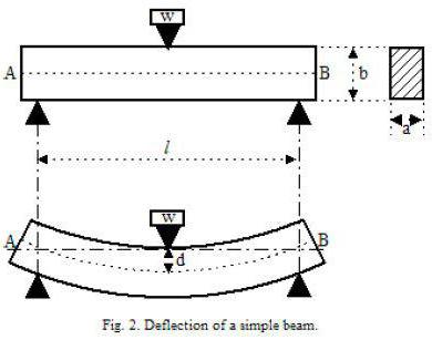
When calculating the deflection of a wooden beam, they are considered freely supported structural elements. In the case for the calculation, a circuit with a load that is evenly distributed is adopted. It is denoted by the symbol q. If the load is concentrated, then a scheme with a concentrated load, denoted by F, is taken. The value of this load is equal to the weight that will put pressure on the structure.
Moment of inertia
The geometric characteristic, which received the name, is important when calculating the beam deflection. The formula allows you to calculate this value, we will give it a little below.
When calculating the moment of inertia, you need to pay attention to the fact that the size of this characteristic depends on the orientation of the element in space. In this case, there is an inversely proportional relationship between the moment of inertia and the amount of deflection. The smaller the value of the moment of inertia, the greater the value of deflection and vice versa. This dependence is quite easy to trace in practice. Everyone knows that a board laid on its edge bends much less than a similar board in its normal position. 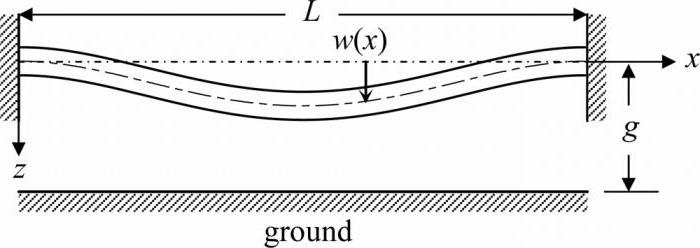
The moment of inertia for a beam with a rectangular section is calculated using the formula:
J=b*h^3/12, where:
b - section width;
h is the height of the beam section.
Maximum Load Level Calculations
The determination of the maximum load on a structural element is made taking into account a number of factors and indicators. Usually, when calculating the load level, they take into account the weight of 1 linear meter of a beam, the weight of 1 square meter of floor, the load on the floor of a temporary nature and the load from partitions by 1 square meter overlap. The distance between the beams, measured in meters, is also taken into account. For an example of calculating the maximum load on a wooden beam, we will take averaged values, according to which the weight of the floor is 60 kg / m², the temporary load on the floor is 250 kg / m², the partitions will weigh 75 kg / m². The weight of the beam itself is very easy to calculate, knowing its volume and density. Let's assume that a wooden beam with a section of 0.15x0.2 m is used. In this case, its weight will be 18 kg / running meter. Also, for example, let's take the distance between the floor beams equal to 600 mm. In this case, the coefficient we need will be 0.6.
As a result of calculating the maximum load, we obtain the following result: q=(60+250+75)*0.6+18=249 kg/m.
When the value is obtained, you can proceed to the calculation of the maximum deflection.
Calculating the value of the maximum deflection
When a beam is calculated, the formula displays all the necessary elements. It should be borne in mind that the formula used for calculations may have a slightly different form if the calculation is carried out for different types loads that will affect the beam.
First, let's bring to your attention the formula used to calculate the maximum deflection of a wooden beam with a distributed load.
f=-5*q*l^4/384*E*J.
Please note that in this formula, E is a constant value, which is called the modulus of elasticity of the material. For wood, this value is 100,000 kgf / m².
Continuing the calculations with our data used for the example, we get that for a beam made of wood, the cross section of which is 0.15x0.2 m, and the length is 4 m, the value of the maximum deflection when exposed to distributed load equal to 0.83 cm.
Please note that when the deflection is calculated taking into account the scheme with a concentrated load, the formula takes the following form:
f=-F*l^3/48*E*J, where:
F is the pressure force on the beam. 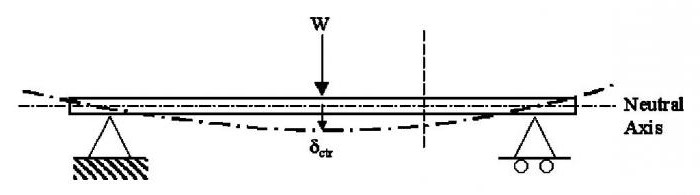
We also pay attention to the fact that the value of the modulus of elasticity used in the calculations may differ for different types wood. The influence is exerted not only by the type of wood, but also by the type of timber. Therefore, a solid beam made of wood, glued beams or logs will have different moduli of elasticity, and hence different meanings maximum deflection.
You can pursue different goals when calculating beams for deflection. If you want to know the limits of deformation of structural elements, then after completing the calculation of the deflection arrow, you can stop. If your goal is to establish the level of compliance of the found indicators with building codes, then they need to be compared with the data that are placed in special regulatory documents.
I-beam
Please note that I-beams are used somewhat less frequently due to their shape. However, you should also not forget that such a structural element can withstand much greater loads than a corner or a channel, an alternative to which can be an I-beam.
Calculating the deflection of an I-beam is worth doing if you are going to use it as a powerful structural element. 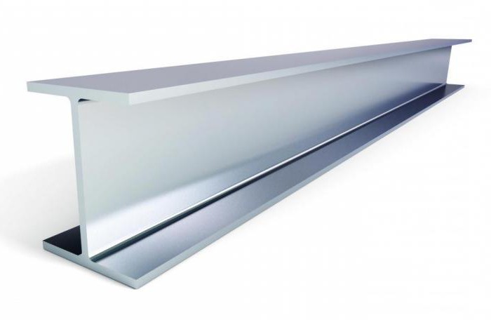
We also draw your attention to the fact that not for all types of I-beams it is possible to calculate the deflection. In what cases is it allowed to calculate the deflection? There are 6 such cases in total, which correspond to six types I-beams. These types are:
- Beam of single-span type with uniformly distributed load.
- Cantilever with rigid termination at one end and evenly distributed load.
- A single-span beam with a cantilever on one side, to which a uniformly distributed load is applied.
- Single-span beam with hinged support type with concentrated force.
- Single-span hinged beam with two concentrated forces.
- Cantilever with rigid termination and concentrated force.
metal beams
The calculation of the maximum deflection is the same, whether it is a steel beam or an element made of another material. The main thing is to remember those values that are specific and constant, such as the modulus of elasticity of the material. When working with metal beams, it is important to remember that they can be made of steel or I-beams. 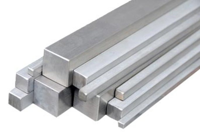 Deflection metal beam, made of steel, is calculated taking into account that the constant E in this case is 2 105 MPa. All other elements, such as the moment of inertia, are calculated according to the algorithms described above.
Calculation of the maximum deflection for a beam with two supports
As an example, consider a scheme in which a beam is on two supports, and a concentrated force is applied to it at an arbitrary point. Before the force was applied, the beam was a straight line, but under the influence of the force it changed its appearance and, due to deformation, became a curve. 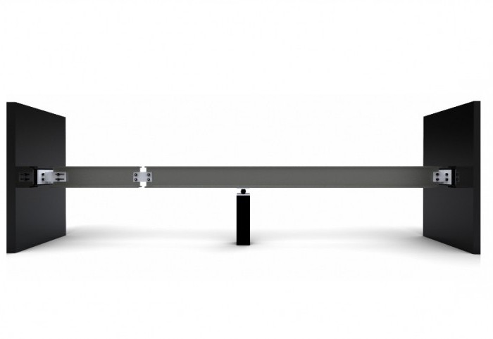
Let us assume that the XY plane is the plane of symmetry of the beam on two supports. All loads act on the beam in this plane. In this case, the fact will be that the curve resulting from the action of the force will also be in this plane. This curve is called the elastic line of the beam or the line of deflection of the beam. Algebraically solve the elastic line of the beam and calculate the deflection of the beam, the formula of which will be constant for beams with two supports, as follows.
Deflection at a distance z from the left beam support at 0 ≤ z ≤ a
F(z)=(P*a 2 *b 2)/(6E*J*l)*(2*z/a+z/b-z 3 /a 2 *b)
Beam deflection on two supports at a distance z from the left support at a ≤ z ≤l
f(z)=(-P*a 2 *b 2)/(6E*J*l)*(2*(l-z)/b+(l-z)/a-(l-z) 3 /a+b 2), where P is the applied force, E is the modulus of elasticity of the material, J is the axial moment of inertia.
In the case of a beam with two supports, the moment of inertia is calculated as follows:
J=b 1 h 1 3 /12, where b 1 and h 1 are the values of the width and height of the section of the used beam, respectively.
Conclusion
In conclusion, we can conclude that it is quite simple to independently calculate the value of the maximum deflection of beams of different types. As shown in this article, the main thing is to know some characteristics that depend on the material and its geometric characteristics, as well as to carry out calculations using several formulas in which each parameter has its own explanation and is not taken from nowhere.
Wooden beams for floors in private construction are often used. Lightness, affordability and the possibility of self-assembly compensate for the ability to ignite, be damaged by fungus and rot. In any case, when building a second or more floors, it is simply necessary to calculate wooden beams overlap. The online calculator that we present in this review will help you cope with this task simply and quickly.