Electronic voltmeter device. Control work: "analog electronic voltmeters.". Electronic analog voltmeters
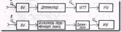
The generalized block diagram of analog electronic voltmeters (Fig. 7.9) contains the maximum number of blocks, some of which, depending on the purpose of the voltmeter, may be absent. In electronic voltmeters equipped with amplifying devices, the power consumption from the measuring circuit is negligible. The advantages of electronic voltmeters include: wide measurement limits and frequency range (from 20 Hz to 1000 MHz), high sensitivity, good overload capacity.
A simple example: the collector current of a transistor must be measured. Instead of breaking the wire between the resistor and the transistor and inserting a multimeter into it to measure current in series, it's easier to write the following: We place the multimeter on a voltage measurement and attach both measurement points to the right and left of the resistor. Thus, many current measurements can be replaced by voltage measurements and are greatly facilitated. Image: Indirect current measurement sketch: The current is calculated from the measured voltage according to Ohm's law.
Figure 7.9.
1. The input device is intended for:
a) attenuation of the signal by a given number of times, allowing to expand the range towards large measured voltages;
b) providing the input parameters of the voltmeter: input impedance within 1 - 10 MΩ, input capacitance 1 - 30 pF.
Amplifiers alternating current serve for:
To measure currents, multimeters usually have two sockets, one for small currents and the other for high currents. Before measuring current, the red test lead must be connected to the corresponding ampere socket. If the current measurement is not clear how much current is expected, it is very important to switch to the high current range first and then switch to the low measurement range. By the way, in the high-precision range, multimeters do not tolerate long-term measurements: the internal shunt, through which most of the current flows, heats up and transfers maximum currents only for a short time.
a) increase sensitivity;
b) expanding the dynamic range towards lower measured voltages.
To perform these tasks, AC amplifiers must have a given and highly stable gain in the operating frequency and temperature range, low non-linear distortion, low intrinsic noise, and be insensitive to supply voltage fluctuations, which is achieved by using multi-stage amplifiers covered by negative feedback.
The term "shunt", which is no longer present, gave a brief explanation: the multimeter as an ammeter measures the maximum current, for example 100 mA at "end deflection". If it exceeds this value, bypass resistors, called shunts, are connected in parallel with the ammeter. They are designed so that most of the current flows through the shunt and less, a maximum of 100 mA through measuring device.
Does the track have hair? What is the value of resistance? These questions are explained by an electronics engineer with a multimeter in the “Ohm measurement” position. The resistance is determined based on the voltage drop across the measurement object. The correct measuring range is important for the result. The measuring voltage must be so high that the components are not destroyed. It is practical to use the ohm range as a continuity tester. On the multimeter, this function is marked with a diode, a buzzer symbol, or a musical notation.
3. DC amplifiers are used to match the small internal resistance of the magnetoelectric measuring mechanism with the large load resistance of the converter. DC amplifiers are subject to stringent requirements regarding the constancy of the gain and low zero drift, i.e., a slow change in the output signal in the absence of an information signal at the input. They are implemented in the form of bridge circuits with negative feedback.
Capacitances and inductance
This makes it easy to measure diodes, conductors and more without looking at the multimeter: when a sound is heard, a whistling sound is heard. If a red measuring tip is applied to the anode, black - to the cathode, then the current of the multimeter flows in the forward direction. If the multimeter has the ability to measure capacitors and coils, look in its user manual for what measurement ranges it knows. It is not always possible to measure the smallest capacitances or even large inductances. Multimeters that have their own connections for capacitors or coils achieve fairly accurate results because no measuring lines are used or flow into the measurement.
4. Converters are used to convert AC to DC, detectors serve as converters. Detectors can be classified according to the function of converting input voltage to output into the following types: quadratic, linear, amplitude (peak). The type of detector largely determines the properties of the device: for example, voltmeters with amplitude detectors are the highest frequency; voltmeters with quadratic detectors allow you to measure voltages of any form; voltmeters with linear detectors are suitable only for measuring a harmonic signal, but are the simplest, most reliable and cheapest.
An unknown capacitor is connected to the provided receive slot, the measurement range is inserted, and the result is read. Measuring capacitors and coils in a circuit is not possible with a multimeter. Practically, who has it, but it comes without - Transistortheor. The counter should show a value between 100 and 900. If you have a measuring device without a transistor, you can still help. This works best with an analog multimeter or digital display, which has a bargraph display below the digital display.
It mimics the pitch of analog instruments and makes trends clear. Image: Practical for electricians, but not suitable for electronics technicians: pure voltmeter. Now use a wet finger to connect the red measuring tip to the base input of the transistor. Correct control, the pointer of the analog multimeter moves, the measured resistance decreases significantly. Use a wet finger between transmitter and base to connect. The meter reacts with the correct transistor with decreasing resistance.
Analog electronic voltmeters can be built according to two main schemes: amplifier - converter and converter - amplifier. The first of the circuits is highly sensitive, but the frequency range of such voltmeters is determined by the bandwidth of the AC amplifier and is hundreds of kilohertz; the second circuit is used in voltmeters to measure voltage at a significant level, since. it is difficult to provide a large gain using a DC amplifier, but the frequency range of such amplifiers and, accordingly, voltmeters can be hundreds of megahertz.
Method 2: The transistor can be thought of as consisting of two diodes. We use this and test two diodes. The multimeter is used for diodetest. The voltage corresponds to the voltage drop across the diode in the forward direction. Measurement with a voltmeter affects the circuit being measured to a small extent! A similar situation arises when measuring current. The measured current is thus less than the theoretically expected value. The multimeter shown in the video has an internal resistance of 100 ohms in a setting to measure current up to 2 mA.
Smartphone, laptop, kitchen utensils, etc. daily. Power supplies are required, devices that require different voltage and current than the power supply. The output voltage and maximum output current can be fixed or variable, as well as direct current or alternating current.
Electronic voltmeters can have an open or closed input with respect to the DC component of the measured voltage. When the input is closed, the voltmeter circuit contains a separating capacitor that does not pass the constant component of the signal; when the input is open, there is no such capacitor, and both the variable and the constant component of the signal are supplied to the voltmeter blocks.
For example, in the field of electronics development, testing systems and the service sector. However, laboratory power supplies are also included in hobby electronics or teaching, such as in universities. This type of power supply includes a transformer that converts the input voltage to the desired secondary voltage. Flux rectification outputs a rectified voltage, which is then applied to the desired DC voltage through the following circuit. Adjustable output voltage implemented using a linear controller.
Element base used to create voltmeters AC voltage, is determined by the level of technology existing at the time of the creation of voltmeters (from semiconductor samples to micro-integral design), however, the functional purpose of the blocks remains unchanged.
AC voltmeters (type B3)
The advantage of this circuit method is that the output voltage is unlikely to contain interference products and the residual ripple is relatively low. However, this type of circuit has an adverse effect on the weight and, above all, on the very low efficiency, which is only about 50%.
This is quite different from switchgear devices where efficiency is between 70% and over 90%, which is especially important for very high power supplies. This is achieved by means of so-called high or low setting devices, which operate, on the one hand, with a significantly higher operating frequency, in the range from 10 kHz to 100 kHz, and on the other hand, with ferrite core cores, which allows a significant increase in efficiency. the whole scheme.
AC voltmeters are built according to the amplifier-converter scheme. Quadratic or linear detectors can be used as transducers.
If quadratic detectors are used, then such voltmeters are called root-mean-square voltmeters, their block diagram is shown in fig. 7.10.
When the output voltage is lower than the line input voltage, the inverter is said to be output voltage above the line input voltage. The disadvantage of this concept is the switched voltages, which show up as disturbances or noise on the output voltage. Thus, the quality of the corresponding power supply is determined by subsequent filters to smooth the output voltage. For higher requirements, linear regulators are usually connected after these power supplies.
The most important selection criteria: voltage, current and power
Distribution and application of two kinds. Even charging device mobile phones at this time rearrange power supplies. Even with these small power supplies, there is a distinct difference in weight. These three variables are the most important decision criteria when choosing a power source. The available output power is the product of output voltage and output current. In some devices, however, there are limitations that the total output power may be required over the entire output voltage range, but the output current from a certain output voltage is either rigid or has the following formula.
Picture. 7.10.
A quadratic detector converts an alternating voltage into a constant voltage proportional, according to formula (7.5), to the square of the rms value of the measured voltage. This means that the measurement of the root-mean-square voltage is associated with the performance of three operations: squaring the instantaneous value of the signal, averaging, and extracting the root from the averaging result (the last operation is usually carried out when calibrating the voltmeter scale). Squaring the instantaneous voltage is usually done using a semiconductor diode, using the initial section of the current-voltage characteristic described by a quadratic dependence. However, the length of the quadratic section of the characteristic is usually small (no more than 100 mV), one of the methods for expanding this section is the method of piecewise linear approximation. To do this, several diode cells are included in the detector circuit and by selecting the bias voltage on the diodes, a total current-voltage characteristic is obtained, approaching in shape a quadratic curve (Fig. 7.11).
By comparison, a single-family home has a heating output of around 5kW through its “heaviest” winter. One of the tools most used by engineers or students aspiring to become engineers in electronics, mechatronics, electromechanics, electronics, etc. Undoubtedly, it is a voltmeter.
A voltmeter is a measuring device that serves to measure the potential difference between two points electrical circuit, these points are what we all know as positive and negative, or also called phase and neutral. Simply put, a voltmeter can measure the voltage provided by a power source or the output of a cell having that value, however, a positive pole is possible for this, and the negative pole must be connected to the inputs or test leads of the meter.
Figure 7.11.
If linear detectors are used in AC voltmeters, then such voltmeters are called medium-rectified voltmeters, the block diagram of such voltmeters is shown in fig. 7.12.
Currently, there are several types of voltmeters, among the most common are digital and analog voltmeters, however there are others that are less common than electromechanical and vector, each of which is used to measure voltage in different conditions.
Analog or analog voltmeter
This instrument is characterized by the fact that it is encapsulated in a small transparent box, inside of which there is a needle passing through a scale of values. They are widely used in electronics projects or platforms that work with flammable gases because they are not so electrical that they are less prone to explosion.
Figure 7.12
In such voltmeters, a linear detector is used as a converter, which converts alternating voltage into D.C., proportional to the average rectified value of the measured voltage. Such converters are made according to full-wave rectification circuits and use the linear section of the current-voltage characteristic of a semiconductor diode. Compared to a rectifier voltmeter, an analog voltmeter of average rectified values has a higher sensitivity and lower power consumption from the measuring circuit. These voltmeters respond to the average rectified value, are calibrated in rms values and have a calibration factor of C=1.
Usually the same instrument cannot measure DC and AC, so you should have one for each type of current. Their measurement scale and physical characteristics change as the price increases. Like an analog voltmeter, they are used to measure the potential difference between two points in a circuit. The only differences between these types of digital and analog meters is that the digital ones have an LCD screen that shows the voltage reading, it is less likely to lose its calibration, but the function they share is that it cannot use the same instrument to measure direct and alternating current.
Pulse voltmeters (type B4)
Pulse voltmeters are built according to the converter-amplifier scheme, an amplitude detector is used as a converter, the output voltage of which corresponds to the maximum (amplitude) value of the measured signal. The block diagram of the pulse voltmeter is shown in fig. 7.13.
This is the least known voltage meter. They are commonly used to measure the voltage of microwave signals. A multimeter is an instrument that collects only the first three in one. The principle of operation of these devices can be analog or digital. Analog instruments are built from a basic unit of great sensitivity called a galvanometer. In general, instruments are designed to measure electrical quantities over a wide range of values. Electronic resistors or amplifiers are used to expand the measurement range of the base units.
Picture. 7.13
A distinctive feature of the amplitude (peak) detector is the presence of a memory element, which is a capacitor that “remembers” the peak value of the measured voltage.
The simplest schemes of amplitude detectors:
a) a detector with a serial connection of a diode (detector with an open input);
b) detector with parallel connection diode (detector with closed input).

Figure 7.14
An amplitude detector converts an AC signal into a DC one, proportional to the value of the input signal, therefore, such voltmeters respond to maximum values, are calibrated at maximum values and have C = 1.
Universal voltmeter (type B7)
The universal voltmeter allows you to measure both direct and alternating current. When measuring AC voltage, the voltmeter has a converter-amplifier circuit. An amplitude (peak) detector is used as a converter, the output voltage of which corresponds to the maximum (amplitude) value of the measured signal. When measuring DC voltage, it is through input device is fed to a DC amplifier and provides a deviation of the pointer of the magnetoelectric measuring mechanism. The block diagram of the universal voltmeter is shown in fig. 7.15.

Figure 7.15 4.12
The amplitude detector converts an AC signal into a DC signal proportional to the maximum value of the input signal, therefore, such voltmeters respond to the maximum signal value and are calibrated in rms values. These AC voltage parameters are interconnected in accordance with (7.7) by the amplitude factor, so the calibration factor of the universal voltmeter is
The characteristics of the considered voltmeters are given in table 7.1.
Table 7.1
|
Voltmeter type |
Converter type |
Voltage value to which it responds voltmeter, Uotk |
The voltage value in which the voltmeter is calibrated, Udeg |
The value of the calibration coefficient, С |
|
Universal |
Max. meaning |
|||
|
Pulse |
Max. meaning |
|||
|
Medium rectifier value |
Middle vypyam. |
|||
|
RMS value |
RMS value |
|||
|
Straighten. |
Middle vypyam. |
|||
|
Thermoelectric |
RMS value |
|||
|
Electrostat. |
||||
|
Electrodyne. |
||||
|
Electromag. |
||||
|
Magnetoelectric |
B / 1 - rectifier with a half-wave rectification circuit
B / 1 - rectifier with a full-wave rectification circuit
To master the course material in the section "Measuring current and voltage", the solution of problems is provided for determining the readings of voltmeters for various forms of measured voltages.
To determine the readings of voltmeters, you must perform the following operations:
1) Burn mathematical model measured voltage;
2) Consider the type of entry; with the input closed, calculate the constant term and remove it from the measured voltage;
3) Find the voltage to which the voltmeter Uotk responds;
4) Find the readings of the voltmeter U=CUotk
Characteristics of voltmeters various systems required in solving such problems are taken from Table 7.1.
It should be noted that the closest measuring instruments to voltmeters are psophometers and level meters.
Psophometer- This is an electronic voltmeter of root-mean-square values, the amplitude-frequency characteristic of the amplifier of which is determined by the characteristic of the psophometric filter included in it. The psophometric filter reflects the frequency response of the selectivity of the organs of perception, and its form is established on the basis of experimental studies and recommendations of the CCITT. Typically, the device includes two psophometric filters - with telephone and broadcast psophometric characteristics.
Level meter- This is a quadratic voltmeter, the scale of which is graduated in logarithmic units (decibels). Specific for the level meter is also the ability to set certain values of input impedance: 600 ohms, which corresponds to the input and output impedances of the voice frequency channel, 150, 135 and 75 ohms for group paths.
REPUBLIC OF KAZAKHSTAN
AVIEK university
FACULTY OF INFORMATION SCIENCE
DISCIPLINE: "Standardization and measurement technologies"
TEST: "ANALOGUE ELECTRONIC VOLTMETERS."
Completed:
St-t gr. ZPOS-96-1
Grinev M.V.
Associate Professor, Ph.D.
Nurmanov M.Sh.
Almaty 2000
VOLTAGE MEASUREMENT WITH ELECTRONIC ANALOGUE VOLTMETER
Electronic analog voltmeters are the first example of electronic measuring instruments covered in the course. Among them, there are both direct conversion voltmeters and comparison voltmeters. Consider the principle of operation, structural diagrams and the main functional units of analog voltmeters for direct conversion and comparison.
ANALOGUE DIRECT CONVERSION VOLTMETER
The block diagram of an electronic analog direct conversion voltmeter corresponds to the typical diagram of fig. 2.1 and, as can be seen from Fig. 3.13, at the very general case includes an input device (VU), to the input of which the measured voltage is applied Ux, IP and a magnetoelectric device used as an IU.
input device in the simplest case, it represents a divider of the measured voltage - an attenuator, with the help of which the measurement limits of the voltmeter are expanded. In addition to exact division Ux, The VU should not reduce the input impedance of the voltmeter, which affects, as has been repeatedly emphasized, the methodological measurement error Ux- Thus, the use of a VU in the form of an attenuator is, in addition to additional
Rice. 3.13. Generalized block diagram of a direct conversion analog voltmeter.
resistances and measuring voltage transformers, another way to expand the measurement limits of voltmeters. It is this method that is used in electronic voltmeters and other radio measuring instruments.
As a power supply in DC voltmeters (V2), a DC amplifier (UCT) is used, and in AC and pulsed current voltmeters (VZ and V4), a detector is used in combination with a DC amplifier or AC amplifier. Converters in voltmeters of other types have a more complex structure. In particular, the converters of selective voltmeters (B6) should provide, in addition to detecting and amplifying the signal, its selection in frequency, and the converters of phase-sensitive voltmeters (B5) should provide the ability to measure not only the amplitude, but also the phase parameters of the signal under study.
The block diagram of the analog DC voltmeter corresponds to the generalized circuit of fig. 3.13. The main functional unit of such voltmeters is the UPT. Modern DC voltmeters are designed primarily as digital instruments.
Voltmeters of alternating and pulsed current, depending on the purpose, can be designed according to one of two block diagrams (Fig. 3.14), which differ in the type of IP. In voltmeters of the first modification (Fig. 3.14, a) measured voltage Ux^ converted to DC voltage Ux=, which is then measured with a DC voltmeter. On the contrary, in voltmeters of the second modification (Fig. 3.14, b) the measured voltage is first amplified by an AC amplifier and then detected and measured. If necessary, a UPT can be additionally connected between the detector and the DUT.
Comparing the block diagrams of Fig. 3.14, even before considering the circuit solutions of their functional units, it is possible to draw certain conclusions regarding the properties of voltmeters of both modifications. In particular, the voltmeters of the first modification in relation to the frequency range of the measured voltages do not have such restrictions as the voltmeters of the second modification, where this parameter depends on the bandwidth of the AC amplifier. But the voltmeters of the second modification have a high sensitivity. From the course "Amplifying Devices" it is known that with the help of an AC amplifier it is possible to obtain a significantly higher gain than with the help of UPT, i.e., to design microvoltmeters with a lower limit Ux^. limited by the amplifier's own noise. Through the change
Rice. 3.14. Structural diagrams of analog voltmeters of alternating and pulsed current:
a - with a detector at the entrance; b - with an AC amplifier at the input.
the division factor of the VU and the gain of the amplifiers, the range of measured voltages can be large for voltmeters of both modifications.
Detector type in block diagrams fig. 3.14 determines whether voltmeters of both modifications belong to voltmeters of amplitude, rms or medium-rectified voltage. At the same time, pulsed current voltmeters (B4) are designed only as voltmeters of the first modification in order to avoid distortion of the pulse shape in the AC amplifier. When measuring the voltage of single and rarely repetitive pulses, either diode-capacitive pulse expanders are used in combination with detectors, or the amplitude-time conversion of pulses, which is typical for digital voltmeters.
Let us now consider a typical block diagram of selective voltmeters, which are used in measuring low harmonic voltages under interference, in the study of the spectra of periodic signals, and in a number of other cases. As can be seen from fig. 3.15, the voltmeter is essentially a superheterodyne receiver, the principle of operation of which is explained in the course "Radio Circuits and Signals".
Frequency selection of the input signal is carried out using a tunable local oscillator, a mixer (Cm) and a narrow-band intermediate frequency amplifier (IFA), which provides high sensitivity and the required selectivity. If the selectivity is insufficient, a two-fold and sometimes a three-fold frequency conversion can be applied. In addition, selective voltmeters must have an automatic frequency control system and a calibrator. Calibrator - exemplary
a source (generator) of an alternating voltage of a certain level, which makes it possible to eliminate systematic errors due to changes in the local oscillator voltage during its tuning, changes in the transfer coefficients of the voltmeter nodes, influence external factors etc. Calibration of the voltmeter is performed before the measurement when the switch P is set from position 1 to position 2.
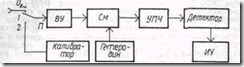
Rice. 3.15. Block diagram of a selective voltmeter.
In conclusion, we note that in one device it is not difficult to combine the functions of measuring direct and alternating voltages, and with the help of additional functional units and appropriate switching (similar to rectifier devices) to form combined devices, called universal voltmeters (B7). Modern types of such voltmeters, as a rule, are designed as digital instruments, which allows them to further expand their functionality and improve accuracy. In this regard, the features of constructing structural diagrams of universal voltmeters will be considered in the works of colleagues.
ANALOGUE COMPARISON VOLTMETER
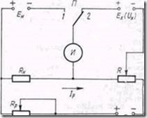
Rice. 3.16. Measuring potentiometer circuit.
Electronic analog comparison voltmeters for the most part implement the most common modification of the comparison method - the zero method. Therefore, they are often called compensatory voltmeters. Compared to direct conversion voltmeters, these are more complex, but, as emphasized earlier, more accurate instruments. In addition, from the diagram in Fig. 2.2 it can be seen that at the moment of compensation DX=0 and the device does not consume power from the source x. With regard to compensation voltmeters, this means the possibility of measuring not only voltage, but also the EMF of low-power sources. In the practice of electroradio measurements, such measurements are performed both with the help of electronic compensation voltmeters and electromechanical ones. To explain the use of the zero method in measuring EMF and voltage, let us first consider the classical circuit of an electromechanical DC compensator shown in Fig. 3.16.
One of the main functional units of any compensator is a high-precision variable resistor. R, on the scale of which the measured value of EMF is counted (Ex) or voltage (Ux). Therefore, it is customary to call compensators according to GOST 9245-79 measuring potentiometers. As an exemplary measure of EMF, normal element(NE) - electrochemical source, EMF (Ea) which is known with a very high degree of accuracy. However, the NE capacitance is small, and a long-term comparison during measurements Ex(Ux) With Yong impossible. Therefore, the potentiometer circuit is supplemented with an auxiliary source of high-capacity EMF (Eo). For comparison with Ex(Ux) the voltage drop across the reference resistor is used Rn., created by the current from the source Eabout- operating current (Ip), which is pre-set. So the measurement process Ex{ Ux) should be in two stages.
At the first stage, the required value of Ir is set. To do this, set the switch to position 1 and use the potentiometer Rp achieve a zero reading of the indicator AND (as a rule, a magnetoelectric galvanometer). As can be seen from fig. 3.16, this corresponds to IPRn=En, i.e., the operating current Ip, which must then remain constant, will reproduce the value during the measurement process En.
At the second stage, the value of Ex(Ux) is measured. To do this, the switch is moved to the position 2, and changing the resistance of the potentiometer R again achieve a zero reading of I. When Ip = const, this corresponds to Ex (Ux) = IPR, i.e. the desired value Ex(U^}^. R and can be measured on a scale R.
Thus, the metrological characteristics of DC measuring potentiometers are determined by the parameters of the NO, reference resistors, indicator, and source Eu. As NE, saturated and unsaturated reversible galvanic cells are used, the positive electrode of which is formed by mercury, and the negative electrode is formed by cadmium amalgam. Accuracy classes of NE are regulated by GOST 1954-82 within 0.0002 ... 0.02 and determine the accuracy class of the potentiometer as a whole. Potentiometer R is performed according to a special scheme that ensures the constancy of /p when changing R and the required number of characters (decades) when counting Ex(Ux). These requirements are met by circuits with replacement and shunt decades.
Measuring potentiometers can also be used to measure alternating voltages. However, the compensating voltage must be regulated in this case not only in absolute value, but also in phase. Therefore, such potentiometers have more complex scheme than direct current potentiometers, and in terms of accuracy they are significantly inferior to them due to the lack of an exemplary measure on alternating current, similar in its characteristics to NE. In the practice of electrical radio measurements, they are completely replaced by electronic compensation voltmeters.
In compensation voltmeters, the measured voltage (DC, AC, pulse) is compared with a constant compensation voltage, which in turn is accurately measured by a DC voltmeter and is a measure Ux. A typical block diagram of such a voltmeter is shown in fig. 3.17.
As can be seen from fig. 3.17, the basis of the voltmeter is a compensation IP, consisting of a measuring diode V s load R, adjustable source of constant compensating voltage -Ek, amplifier and indicator with two stable states. With absence Ux indicator implemented using
functional nodes is in the first stable state, and at a certain threshold value it goes into the second state. Measurement process Ux is reduced to a gradual increase Ek until the indicator enters the second stable state. Meaning Ek, corresponding to the moment of transition, is measured by a DC voltmeter and is a measure Ux.

Rice. 3.17. Block diagram of a compensation voltmeter.
In combination with other circuit solutions (the use of an indicator with a low threshold voltage, a lamp measuring diode with a stable characteristic, etc.), it is possible to design high-precision compensation voltmeters.
The disadvantage of the considered scheme is the need to install Her manually. Therefore, in most voltmeters, the IP circuit is complicated by providing automatic compensation Ux and Ek. Auto-compensation voltmeters are direct-reading instruments and are more convenient to use.
MAIN PARTS OF ANALOGUE VOLTMETER
Consider circuit solutions of the main functional units that determine the metrological characteristics of analog voltmeters. Most of these nodes are used in other types of electronic measuring instruments.
input device
As mentioned above, the WU is designed to expand the measurement limits of the voltmeter. In the simplest case, it is an attenuator made according to resistive (Fig. 3.18, a), capacitive (Fig. 3.18, b) or combined (Fig. 3.18, c) schemes.
The fulfillment of the remaining requirements and, above all, the provision of a high input resistance and a minimum input capacitance of the voltmeter in some cases leads to a complication of the WU structure. The most versatile and frequently used in modern AC voltmeters is the VU, the block diagram of which is shown in fig. 3.19.
The fundamental feature of this circuit is the change in Uv using a low-resistance resistive attenuator with a constant input and output impedance. This improves measurement accuracy. Ux~, but requires the introduction of an impedance converter (PI) into the structure of the VU, which ensures the transformation of the high input resistance of the voltmeter into a low input impedance of the attenuator. As a PI, a voltage follower on a field-effect transistor with deep negative feedback is most often used. By using
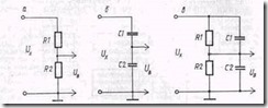
Rice. 3.18. Voltmeter attenuator circuits:
a-on resistors; b - on capacitors; c - combined.
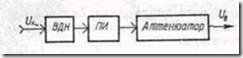
Rice. 3.19. Structural diagram of the universal input device.
input voltage divider (VDN) provides an additional opportunity to expand the measurement limits of the voltmeter. VDN is a fixed resistor-capacitive divider (see Fig. 3.18, in)
At high frequencies, the input resistance of the voltmeter decreases, and the input capacitance and inductance of the conductors form a series oscillatory circuit, which has almost zero resistance at the resonant frequency. To neutralize these effects, the PI is designed as a remote probe with VDN in the form of a nozzle.
Amplifiers
DC amplifiers, as can be seen from the block diagrams (see Fig. 3.13 and 3.14, o), provide sufficient power to drive the IM of a magnetoelectric device, and match the input impedance of the DUT with the output impedance of the VU or detector. Two main requirements are imposed on the UPT: high constancy of the gain and negligible fluctuations of the output value in the absence of Ux= (Drift zero). That's why everything practical schemes UPTs have a deep negative feedback (NFB), which ensures their stable operation and insensitivity to overloads. Radical methods of combating zero drift are its periodic correction, as well as the transformation Uх= into an alternating voltage with subsequent amplification and rectification of this voltage.
AC amplifiers, in accordance with their functional purpose (see Fig. 3.14, b), must have high sensitivity, great importance and high gain stability, low non-linear distortion and wide bandwidth (with the exception of the IF selective voltmeter). Only multi-stage amplifiers with OOS and links for correcting the frequency response can satisfy these conflicting requirements. In some cases, logarithmic amplifiers are used to obtain a ^ linear scale in decibels. If the task is to minimize the additive error of the voltmeter, the amplifiers can be two-channel with amplification of the main signal and the signal that corrects the additive error. To expand the functionality, many voltmeters have a special amplifier output and can be used as broadband amplifiers. Moreover, amplifiers can be produced as independent measuring instruments, forming a subgroup U.
DC and AC amplifiers are discussed in detail in the Amplifying Devices course.
Detector
The type of detector determines, as already mentioned, whether AC voltmeters belong to amplitude, rms, or average-rectified voltage voltmeters. In accordance with this, the detectors themselves are classified as follows: according to the parameter Ux~^ which corresponds to the current or voltage in the output circuit of the detector: peak detector, rms and average rectified voltage detectors; according to the input scheme: detectors with open and closed DC voltage inputs;
according to the detection characteristic: linear and quadratic detectors.

Rice. 3.20. Peak detector circuits:
A - with an open entrance; B - c closed entrance.
Peak Detector - it is a detector whose output voltage directly corresponds to t/max or<7min (Ov or Us). The peak detector is linear and can have an open (Fig. 3.20, a) or closed (Fig. 3.20, b) DC voltage input.
The principle of operation of peak detectors is specific and consists in charging the capacitor C through a diode V up to the maximum (peak) value Ux~ , which is then stored if the discharge time constant C (via R) much larger than the charge time constant. Switching polarity V defines a Ux= match, or Umax(Uin), or Umin(Un), and possible pulsations U x= are smoothed by a chain RF, SF. If the detector has an open input, U x= is determined by the sum U and Uin(Un), i.e. corresponds to Umax (Umin) With closed inlet U x= corresponds Uin(Un). If Ux~ does not contain a constant component, then the circuits shown in Fig. 3.20, a, b, are identical, and U x= corresponds um. In some cases, full-wave peak detectors with voltage doubling are used, allowing direct measurement of the voltage peak-to-peak value.
An essential advantage of peak detectors is their large input impedance (equal to R/2 for the circuit in fig. 3.20, a and R/3- for the circuit in fig. 3.20, b) and the best frequency properties compared to other types of detectors. Therefore, peak detectors are most often used in voltmeters of the first modification (see Fig. 3.14, o), being structurally designed together with the VU in the form of an external probe. In this case, the cable connecting the probe to the device transmits Ux=.
RMS detector - it is an AC to DC converter (voltage) proportional to U 2 sk. The detection characteristic in this case should be quadratic, and when on. If U- a detector with an open input is required. In modern types of voltmeters, mainly quadratic detectors with thermal converters are used, similar to converters of thermoelectric ammeters. Their main disadvantage, as noted earlier, is the quadratic character of the instrument scale. In voltmeters, this drawback is eliminated by using a differential circuit for switching on two (or more) thermal converters, as shown in Fig. 3.21.
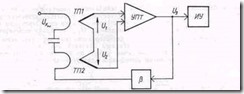
Rice. 3.21. Structural diagram of the RMS voltage detector.
When the measured voltage is applied to the thermal converter TP1 Ux~ output voltage TP1 by analogy with (3.26) U 1 =k t U 2 sk.
In addition to TP1, the circuit has a second thermal converter TP2, which is connected opposite to TP1. A feedback voltage is applied to TP2, so it
output voltage U 2 == k t BU 2 3 .
Thus, at the input of the UPT, there is a resulting voltage
U 1 - U 2 = kt(U 2 sc - BU 2 3)
what does
U 3 \u003d k upt k t (U 2 sk - BU 2 3).
If the scheme parameters are chosen so that
k upt k t BU 2 3 >> U 3 ,
then finally U 3 º Usk, i.e. the DUT scale will be uniform.
Average rectified value detector - this is a converter of alternating voltage to direct current, proportional to Usv. Schematically, it is based on a full-wave semiconductor rectifier, considered in the analysis of rectifier ammeters (see § 3.4.1). However, it should be added that the linearity of the characteristics of such detectors will be the better, the more Ux~(for small Ux~ detector becomes quadratic). Therefore, detectors of the average rectified value, as a rule, are used in voltmeters of the second modification (Fig. 3.14, b).


