Photorelay street lighting. How to independently connect a photorelay for outdoor lighting
I was personally concerned about the topic of how to organize additional illumination of seedlings in a not very bright room. The fact is that my tomato-pepper nursery is organized in a workshop at the garage (so as not to litter in the house). So, there is one window to the west, and even darkened by the terrace of the second floor above it. In short, hellish little light, however!
Actually, my lighting is organized by a design of four LED spotlights suspended from the ceiling above the seedlings. But they need to be turned on in the morning and turned off in the evening (such a cycle of life in plants, unlike people who sleep and wake up, is sometimes very intricate). Someone say, what's the problem? Well, turn it on and off, or is it already too lazy ?! For such evil people, I will explain that I have to constantly leave for two or three days a week. And this is already a problem. There is no one on the hacienda, except for video cameras, which, as you know, have other important tasks.
So let's go! It is necessary to make a photorelay, which will turn on the lamps at dawn and turn off in the evening at dusk. I took the circuit I tested earlier on the thermal relay for turning on and off the cooling fans in the power supply, which I wrote about earlier.
Just tweaked it a little. Naturally, instead of a thermistor, I used a photoresistor FR-765. And the value of the resistor R1 increased to 820 com. I tested the operation of the circuit on a breadboard, powered by a laboratory source.
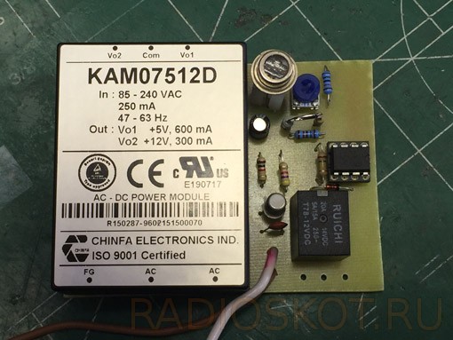
I took an existing 12v AC-DC converter as a power source for the circuit. It was ideally assembled together with the board in a small case. I did not use an indicator LED, since the indication clearly occurs by turning on four spotlights of 100 watts each (how can you not understand that - Hooray! It worked!).
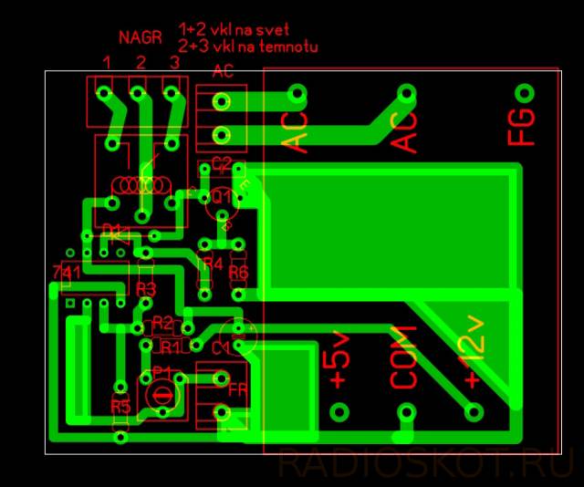
I made the layout of the board in Sprint-Layuot, taking into account the layout in the case.
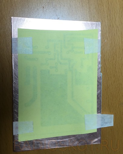
And then you need to make a board using the LUT method (laser ironing technology). I printed a board drawing on a laser printer (I have HP) on yellow Chinese thermal paper (I like it the most out of everything I've tried, as it consistently gives results when transferring an image to foil fiberglass and is easily separated from it after transfer). In the printer settings, you need to set the maximum toner consumption. The board blank is sanded with zero and degreased with acetone. I make the board blank a little more than right size to fix the paper with the pattern on it using strips of masking tape 20 mm wide (this is 20 mm wide tape, not strips), which are glued as shown in the photo and folded over the edges of the workpiece. Masking tape securely holds the paper on the workpiece when it is heated with an iron, does not melt and easily separates afterwards without leaving any traces. I came to this after many different experiments, as to the most optimal way of fixing. That's about it.
Further actually LUT. The iron is set to the highest temperature. While it is warming up, I put the board blank on the board with the paper with the pattern facing up. I cover it with a sheet, folded in half, of ordinary office paper. I also cover the top with a thin waffle towel folded in half, which are now sold as rags for a penny. Then I begin to iron this sandwich with an iron with a little pressure for a minute and a half. Then I leave the workpiece to cool naturally. When she cools down room temperature, carefully separate the paper from the copper layer of the workpiece.
It is important here to properly withstand the warm-up time so that the toner does not dry out. I overexposed a little, so the flaws are corrected with an acid-resistant marker.
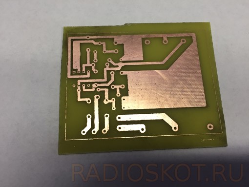
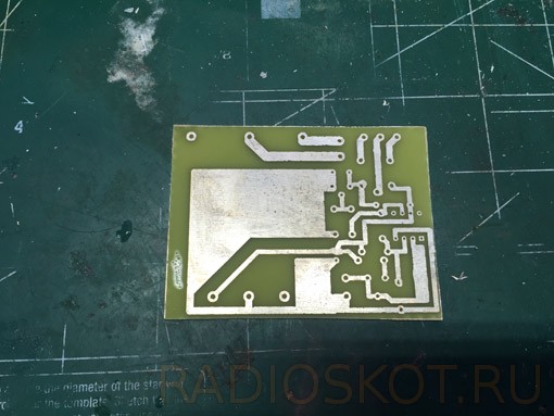
Next up is bullying. I will not describe it, the procedure is known. After etching, we wash off the toner from the board with a swab moistened with acetone. Here's what happened. Not god knows, but acceptable.
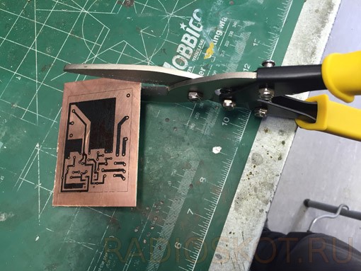
Next, cut the workpiece to size. To make this easy to do, when laying out the board in Sprint-Layout, I select the option with the outline of the board. I cut the board to size along these lines. What would you think? Scissors ..., for metal. They perfectly cut textolite and there is no dust, like from a hacksaw.
Next, you need to irradiate the board. For this I use Rose alloy. This alloy has a melting point of about 99 degrees. In a small metal container with a non-stick coating (the molten alloy does not stick to it) with water on a portable gas stove, I melt a piece of Rosé alloy (you need to add a little citric acid to the water, about a teaspoon without a slide per glass of water), put the board there with a pattern on the melted alloy (similar to mercury, just as mobile), I press it a little by moving the board back and forth, then I turn the board over with the pattern up. With a silicone spatula (of which there are a lot in the household departments), I rub the molten alloy over the surface of the drawing, tinning it with a thin layer. Here's what happened.

I tried hand micro drills, but this is not it. Here the drill is fed strictly vertically (I use German carbide drills, which, although they cost 150 rubles a piece, are worth it) and the probability of breaking it is extremely small. Unless in an inadequate state, but in this case it is better to do something else, for example, look at the world widely with a beefy look. Well, now we assemble the circuit on the board. Here's what happened.
If the installation is done correctly, the circuit starts immediately. Adjustment consists in adjusting the light thresholds of the relay operation with a tuning resistor. I set it to about 30 lux with some hysteresis set by the feedback resistor R3.
Speaking of hysteresis. I also chose this scheme because when the relay is triggered at the limit values (both in the thermal relay and in the photo relay), there is absolutely no bounce of the relay contacts. Operations are clear. Although, we know how slowly the illumination changes during morning and evening twilight. But even in this case there are no border effects. Here is the finished product with the load power socket.
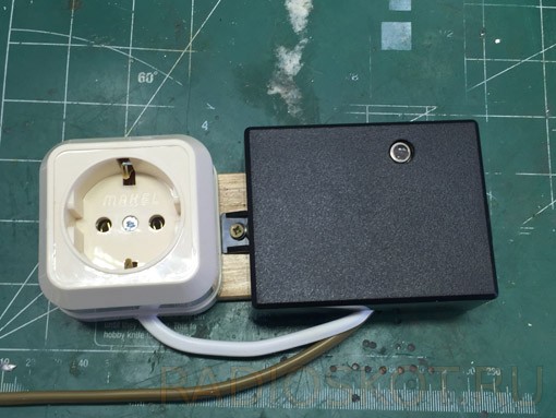
And this is it at work.

Well, now there is one less problem. And further. This photorelay can also be used in the mode of turning on the light with the onset of darkness and turning it off with increasing illumination. That is, how to automatically turn on the lighting of something at night. For this, only another relay contact is activated. You can see it on the PCB drawing. All the best!
Many people today strive to create in their own home optimal conditions for relax. Increasingly, various elements of the "smart home" system are used to equip private houses. For example, for street lighting, a special sensor is often used - a photorelay.
With the help of a photorelay, you can create a system for turning on the light on the street in automatic mode at nightfall and twilight. Such a photo sensor costs quite a lot, which makes it an infrequent guest in private homes. But if you have the skills to assemble electrical appliances, then you can easily assemble such a photo sensor with your own hands. There is nothing super complicated here, and if the installation was successful, then the street-type lighting system will work no worse than with a purchased sensor. How you can assemble such a sensor and what you need to know for this, today's article will tell.
Technical minimum for assembly
At the very beginning, if you want to design a photo relay with your own hands to automate the inclusion of a street type of lighting, you need to draw up, so to speak, an “action plan”, because when everything is systematized, then it will be easier to do. For simplicity, you can use the following algorithm:
- understand the principle by which the photo sensor functions in order to correctly assemble its electronic filling;
- find out what characteristics the device should have;
- find out what type of sensor you will be collecting;
- purchase the entire list of parts necessary for assembling the device with your own hands.
Note! With self-assembly of the photo relay, the control of the device will be solely on your shoulders. Therefore, the entire success of the enterprise and the final result will depend on how you prepare for the case.
The most important thing to know in this matter is that the case of such a device must be sealed in order to provide a high degree of protection of the product from a variety of weather conditions. After all, this sensor will be an element of a street-type lighting system.
In general, the assembly process of the photorelay relies on many nuances that also need to be remembered. This should include the following points:
- The photo sensor in its circuit must contain protective elements that will prevent false operation of the device and turning on the light when it is not necessary. If this is not done, then the device will not be able to effectively cope with its duties, and you will not get the desired level of comfort;
Note! If you do not install protection, then various interference will affect the operation of the sensor.
Sensor circuit with protection
- the quality of the details. Remember that the service life of any home-made electrical appliance, including a photorelay, directly depends on the quality of the parts used to assemble it. Therefore, you need to buy parts only from trusted sellers or in stores specialized in radio electronics;
- you need to know what types of photorelay can be used to turn on the light on the street.
If everything is more or less clear with the quality of parts, then few people know which photo sensor is applicable for street lighting.
Device options
Scheme of a shield with a photocell
Assemble with your own hands, with due diligence, you can different types photorelay that can be used in a street-type lighting system. To automatically turn on the light on the street, you can use various photocells that are sold on the market.
Note! Different models of photo sensors not only have different design features, but are also controlled in different ways. In this regard, you need to know that the connection of the photo relay directly depends on the type of device used.
The sensor with a photocell can be of the following types:
- a product whose shield will contain a special photocell. This photo sensor is used to turn on the light at dusk. In this case, the device turns off when it catches the first rays of the sun. Such models are fully automated. The sensor itself has a transparent housing. It protects the photocell from various adverse climatic conditions, as well as from mechanical damage;
- sensor that allows you to adjust the threshold. The device control method will be almost the same as the previous model. At the bottom of such a photorelay contains a special switch. With it, it is possible to adjust the threshold for the operation of the photocell. Such devices are the most popular;
Note! Setting the switches to "+" will automatically turn on the light when it gets dark (during a thunderstorm or rain). When set to the "-" mode, the photocell will only work in the dark.
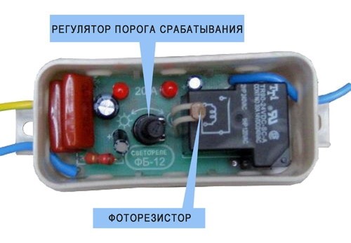
Device with adjustment

Sensor circuit with timers and photocell
- sensor, which in its design contains both a photocell and a timer. This device, like the previous ones, is designed to control street lighting. It also uses the automatic mechanism of the sensor. The shield, where the timer will be placed, allows a person to independently control the lighting period. Using the control panel of the device. you can independently make adjustments to time intervals when lighting is required. In a given situation, when lighting is reached maximum level, the appliance will turn off automatically. Such models allow significant energy savings.
In addition, the components of the product themselves may be different. For example, a timer for different sensors can be:
- daytime;
- weekly;
- annual.
Using different timers, you can debug the photorelay for a specific job, depending on your needs.
Remote instrument

Photorelay with remote photocell
Separately, it is worth noting that there are special types of photo relays, in which the photocell is taken out separately.
Here there are some features and the installation of such a device is somewhat different:
- the control mechanism and the main unit will be at a sufficient distance from each other. The distance between these elements can reach 100 m;
- the electrical panel with the installed photorelay unit can be placed anywhere you want.
Thanks to this design, you will be able to place the device in a place that is more protected from various climatic conditions. As a result, the sensor will serve you much longer than models with built-in photocells.
Any version of the photorelay can be made by hand. The main thing is to install the device correctly and connect it so that it can effectively perform its functions to turn on the lighting on the street at the right time.
Self assembly
Depending on what type of photorelay you have chosen, the scheme of its assembly will also depend. In this article, we will consider a simple scheme, according to which it will be possible to assemble the device with our own hands without any problems.
At its core, the sensor with a photocell contains a phase regulator for power (KR1182PM1). When it's day outside, the VT1 photosensor is illuminated. The current flowing through its transition closes the triacs inside the microcircuit. As a result of this, the VS1 triac will be closed, and the EL1 lamp will not light up.
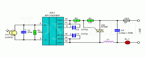
Assembly diagram
When evening comes, the illumination of the photoresistor VT1 decreases. As a result, the current that flows through its junction also decreases. This leads to the fact that transistors are "unlocked" in the microcircuit. They, in turn, contribute to the opening of the triac VS1 and the activation of the lamp.
Due to the fact that the assembly circuit of such a sensor does not contain threshold elements, the activation of the lamp and its deactivation occur smoothly. In addition, the high sensitivity of the photorelay allows the light source to turn on at full power only at full twilight.
To reduce interference in the operation of such a device, the L1 choke, as well as the capacitor C4, should be included in the circuit.
As a capacitor, it is necessary to take K73-16 or K73-17 with a voltage of at least 400 V. You can also use K50-35 capacitors.
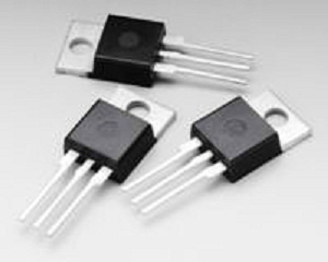
A triac VS1 must be installed on a radiator with a surface area of 300 cm2. We make the throttle from two glued rings (ferrite) K38x24x7 (you can take the M2000NM brand).
We wind the winding in one layer, which should contain 70 turns of PEV-2 wire, having a diameter of 0.82 mm.
Note! A properly assembled photo relay does not need to be adjusted. If it becomes necessary to increase the sensitivity, it is worth including another phototransistor in the circuit. It will run in parallel. When setting up, be sure to take precautions, as all components of the device will be energized.
Another build option
Assembly Components
There is also a slightly different way. Here, the assembly is carried out on the basis of a TeccorElectronics Q6004LT semiconductor integrated device. It is a triac with a built-in dinistor. This device is characterized by an operating current of 4 A, and an operating voltage of 600 V.
Here you will need:
- instrument Q6004LT;
- photoresistor;
- normal resistor.
The resulting device will be powered by a 220V mains. The principle of operation of this scheme is as follows:
- light forms a small resistance on the photoresistor. At the same time, there will be a small voltage on the control electrode of the square;
- the square remains closed. As a result, no current will flow through it;
- when the illumination decreases, an increase in resistance will be observed on the photoresistor, which will lead to an increase in the voltage pulse supplied to the control electrode;
- an increase in the voltage amplitude to the mark of 40 V will lead to the opening of the triac and current will flow through the circuit. As a result, the light will turn on.
To tune this circuit, you need to apply a resistor. Its initial resistance should be 47 kOhm, but the resistance value should be selected depending on the type of photoresistor used in the circuit. As a photoresistor, you can use the following elements: FSK-7, SF3-1 or FSK-G1.
The use of a powerful Q6004LT device makes it possible to connect a load with a power of up to 500 W to the assembled device. And the use of an additional radiator in the circuit will increase the power to 750 watts. In the future, you can use a quad, which will have operating currents of 6, 8, 10 or 15 A.
The main advantages of this assembly scheme are a minimum of parts, the absence of a power supply, and the possibility of increasing power. Thanks to this, the self-assembly of such a device will take place quickly and without problems, even if a beginner undertakes it.
Connecting the device
A sensor with a photocell is an indispensable thing in private homes with a vast backyard area. This device will allow you to automatically turn on the lighting on the street at dusk.
by the most the best option for installation, according to experts, is a photorelay with the ability to adjust the response threshold. The assembly of such a device, as well as the connection of the photorelay, can be completely done with your own hands, without the involvement of a specialist.
Note! This model will be an excellent acquisition for summer cottages and city yards.
Regarding how to connect a photo relay, which was assembled by hand, this is already the topic of a separate article. In this situation, the main attention should be paid to the device model, since different assembly options have different connection methods. In principle, anyone, even a beginner in the assembly of electrical appliances, will cope with this task.
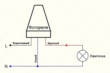
Photo relay installation
Remember that when connecting a photo relay to create street lighting, you must be very careful not to get an electrical injury.
As you can see, it is not very difficult to assemble a photorelay with your own hands in order to automate the process of lighting the street space. The main thing is to follow the chosen assembly scheme and use quality parts.
Photo sensors and electronic devices implemented on their basis that control various household appliances have long gained popularity.
It would seem that it is already impossible to find anything new in the circuit design for such devices. Below I offer readers three reliable circuits that are simple and highly sensitive to the light flux acting on the sensors.
These simple photorelay circuits can be used in your automation designs and in control devices.
Self-Locking Burglar Alarm Device
A simple and reliable self-locking burglar alarm device is shown in the circuit diagram (Fig. 1).
Fig 1. Burglar alarm with self-locking.
The device is used as a light detector: the HL1 LED lights up if the photocell - photoresistor PR1 does not get natural or electric light. In practice, this electronic node will help in monitoring the security zone of a house or garden plot.
While the photoresistor PR1 is illuminated, its DC resistance electric current small, and the voltage drop across it is not enough to unlock the thyristor VS1.
If the flow of light acting on the photosensor is interrupted, the resistance PR1 increases to 1 ... 5 MΩ, then the capacitor C1 begins to charge from the power source.
This leads to the unlocking of the thyristor VS1 and the inclusion of the LED HL1. Button S1 is designed to return the device to its original state.
Instead of the HL1 LED (and the current-limiting resistor R2 connected in series with it), you can use a low-power electromagnetic relay of the type RES 10 (passport 302, 303), RES 15 (passport 003) or similar with a trip current of 15 ... 30 mA. As the power supply voltage increases, the current consumption of the relay increases.
Instead of the thyristor KU101A, you can use any thyristors of the KU101 series. The PR1 photosensor consists of two SFZ-1 photoresistors connected in parallel (for better sensitivity there is no need for an additional signal amplifier). Capacitor C1 type MBM, KM or similar.
LED - any. All fixed resistors type MLT-0/25. Button S1 can be any. In the author's version, the MPZ-1 microswitch was used.
Op-amp light sensor
On fig. 2 shows a diagram of a light sensor with an amplifier based on the K140UD6 operational amplifier.
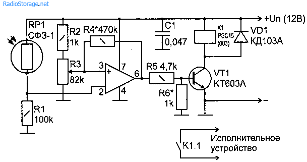
Rice. 2. Scheme of the light sensor on the OS.
The value of the resistance of the resistor R4 is set for a power supply voltage of 12 V. As Un increases, the resistance of the resistor R4 must be selected more accurately. The sensitivity of the device is regulated by a variable resistor R3.
Operational amplifier DA1 is included according to the classical scheme with a gain of 1. Diode VD1 protects the transistor VT1 from reverse voltage surges when the relay is triggered.
Instead of the K140UD6 chip, you can use the same type of operational amplifiers K140UD608, K140UD7 without changing the circuit. Capacitor C1 serves in the circuit for filtering high-frequency voltage noise. Transistor VT1 can be replaced with KT315A-KT315V, KT312A-KT312V. Variable resistor R3 type SPZ-1VB.
Photorelay on the timer KR1006VI1 (555)
On fig. 3 shows a circuit with a universal timer KR1006VI1.
This simple machine for turning on night lighting can be effectively used both in urban areas and in the country or in the countryside.
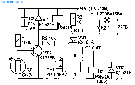
Rice. 3. Electrical circuit diagram of a photorelay (photo-sensor) based on the KR1006VI1 timer.
If at least a weak daylight- transistor VT1 closes, since the resistance between its base and emitter is much less than the resistance between its base and the positive terminal of the power source.
When the illumination of the working surface of the photoresistors decreases, the resistance between the base and the emitter of the transistor VT1 increases - it becomes more than 100 kOhm.
When the resistance between the base of VT1 and the positive terminal of the power supply is low, the transistor VT1 opens. Relay K1 is activated and connects the output of the anode of the thyristor VS1 to the "plus" of the power source.
After that, the universal timer DA1 KR1006VI1 is turned on and a voltage of 10.5 V is set at its output (pin 3).
K1006VI1 has a sufficiently powerful output (pin 3) that allows you to control load devices that consume current up to 250 mA. Therefore, low-power relays without a key transistor cascade can be connected to the DA1 output.
Relay K1 is activated and keeps the lighting lamp HL1 on. Instead of a lamp, it is possible to use another active load with a power consumption of not more than 0.2 A (this parameter is due to the characteristics of a low-power relay).
So the load ( electric lamp lighting) is always on until at least a minimum luminous flux acts on the photosensor.
The device has passed experimental tests and works reliably, it is used in the author's version to turn on energy saving lamp illumination in the evening and at night (the photo sensor is turned to natural light). Due to the high sensitivity of the device, the lighting lamp turns off when the sun rises.
Thyristor VS1 - KU101A-KU101G, KU221 with any letter index. Transistor VT1 can be replaced with KT312A-KT312V, KT3102A-KT3102Zh, KT342A-KT342V or similar in electrical characteristics.
The current gain of this transistor h21e must be at least 40. The relay is any low-power relay, with a trip current of 15 ... 30 mA at a voltage of 12 V. All fixed resistors are of the MLT-0.125 type. Capacitor C1 type KM. C2 - type K50-20 for an operating voltage of more than 16 V.
Diodes VD1, VD2, respectively, protect the transition of the transistor VT1 and the output of the DA1 chip from surges alternating current and prevent the bounce of the contacts of the corresponding relays K1, K2 when they are triggered. Such diodes can be replaced with any of the KD522 series.
All three circuits are undemanding to the supply voltage and, when used as switching nodes of low-power relays, they work stably with transformerless (capable of delivering a useful current of more than 70 mA) and transformer stabilized power supplies with an output voltage of 10-16 V.
Literature: Kashkarov A.P. Electronic devices for coziness and comfort.
Such schemes are called photorelay, most often this is a simple inclusion of lighting in the dark. To this end, many schemes have been developed by radio amateurs, here are some of them.
Probably the simplest circuit is shown in Figure 1. The number of parts in it is small, it will not work out less, and the efficiency, read sensitivity, is quite high.
Setting up the device comes down to setting the threshold voltage so that it turns on already at dusk. In order not to wait for this natural moment, it is possible to illuminate the photodiode in a darkened room with an incandescent lamp switched on through a thyristor power regulator. The same technique is suitable for tuning other photorelay circuits.
It is possible that when the photorelay is triggered, the relay will rattle. You can get rid of this phenomenon by connecting in parallel the coil for several hundred microfarads.
Photorelay on a microcircuit
A specialized one is a phase power regulator, the same as a conventional thyristor. A very important and valuable property of such a power regulator is that it is included in the circuit as a two-terminal network, without requiring an additional power wire for itself: just turn it on in parallel with the switch and everything is already working! Figure 4 shows how a simple photorelay can be built on this microcircuit.
Rice. 3. Chip KR1182PM1
Figure 4. Photo relay circuit on the KR1182PM1 chip
The control pins of the microcircuit are 3 and 6. If you connect just an ordinary single-pole switch between them, then when it is closed, the load will be turned off! If it is opened, the load will be connected. By the way, without additional external thyristors or a triac, and even without a radiator, the microcircuit can withstand loads up to 150W. This is the case if, when the load is turned on, there are no current surges, like incandescent lamps. An incandescent lamp in this embodiment can be turned on with a power of not more than 75W.
Just connect the switch to these conclusions as if to nothing, if only in combination with other details. If you do not pay attention to the phototransistor and the electrolytic capacitor, mentally leave only the variable resistor R1, then you get just a phase power regulator: when you move its engine up in the circuit, pins 3 and 6 are short-circuited, thereby disconnecting the load, like the contact mentioned above. When moving the slider down the circuit, the power in the load changes from 0 ... 100%. Everything is clear and simple here.
If we connect an electrolytic capacitor to these conclusions (we assume that there is no phototransistor in the circuit yet), then we get just a smooth turn on of the load. How?
The resistance of a discharged capacitor is small, so at first the control pins of the microcircuit 3 and 6 are practically short-circuited and the load is turned off. As the charge increases, the resistance of the capacitor increases (just remember to check the capacitors with an ohmmeter), the voltage across it also increases, the power in the load increases smoothly. It turns out a device for smooth switching on the load. Moreover, the power to the load will be supplied as much as the engine of the variable resistor R1 is introduced. When the device is disconnected from the network, the capacitor is discharged through the resistor R1, preparing the device for the next connection. If the capacitor does not have time to discharge, then there will be no smooth switching on.
Now we got to the most important thing, to the photo relay. If we now connect a phototransistor to control pins 3 and 6, we get a photorelay. It works as follows. In the daytime, at high illumination, the phototransistor is open, so the resistance of its collector-emitter section is small, pins 3 and 6 are closed to each other, the load is turned off.
With a smooth decrease in illumination in the evening hours, the phototransistor will smoothly open, gradually increasing the power in the load, that is, in the lamp. There are no threshold elements in this circuit, so the lamp will light up and go out gradually.
So that the photo relay does not work at the moment when its own lamp turns on, it is desirable to protect the phototransistor from such illumination. The easiest way to do this is with a plastic tube.
The task of the photorelay is to control the lighting, often it is a circuit with a photosensitive element that controls the inclusion of lighting in the dark. Radio amateurs have developed many various schemes photorelay, we present to your attention simple and reliable circuits on various photosensitive elements: photoresistors, photodiodes, phototransistors.
The first photo relay circuit on a photodiode is quite suitable for beginners, as it is easy to manufacture and does not contain rare elements. An LED was used as a load after the key, of course, another logic circuit or relay can be used instead. In this circuit, the photodiode is connected through a current stabilizer, the circuit in this connection gives a significant difference in lighting and darkening the photosensitive element and therefore does not require an additional amplifier. With a sharp change in illumination, the voltage on the photodiode changes from 0 to the level of the supply voltage of the circuit. You can easily assemble and adjust this circuit in a couple of hours on a breadboard. The photodiode can be used by almost any brand.
In this circuit, FD 256 was used, but the circuit also works with phototransistors. VD1 and VD2 you can put any silicon diodes. Transistors can also be any low-power ones. As I said, the first transistor works as a current stabilizer and the larger R2 is, the greater the sensitivity of the circuit, but do not overdo it with the setting. The cascade on the second transistor is an emitter follower, the third transistor is a regular key.
We offer Another simple scheme with a minimum number of parts, and high sensitivity. This sensitivity is achieved by including transistors VT1 and VT2 as a composite. In such an inclusion, the total gain will be equal to the product of the coefficients of the constituent transistors. Also due to this inclusion, a high input impedance, which allows the use of a photoresistor and other high-resistance signal sources.

Principle of operation:
The circuit works very simply - with increasing illumination, the resistance of the photoresistor decreases to a few kiloohms (in the dark - a few megaohms), this leads to the opening of the transistor VT1. The collector current VT1 will open the transistor VT2, which in turn will turn on the relay and it will turn on the load with its contacts. So that at the moment the relay is turned on, self-induction does not occur and the low-power signal of the photoresistor is converted into a signal sufficient to turn on the winding, the signal is turned on VD1.
To adjust the sensitivity of this circuit, which can sometimes be excessive, you can put a variable resistor in the circuit, which is shown in the diagram by a dotted line. The power supply of the circuit depends on the operating voltage of the relay and can be in the range of 5-15V. 12 volts RES 15, RES 49. The winding current when using these transistors should not exceed 50 mA. if you put instead of VT2, a more powerful type KT 815, the output can be large and it is possible to use more powerful relays. It should be borne in mind that with increasing power, the sensitivity of the photorelay increases.
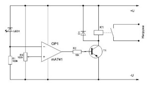
Another diagram is assembled on operational amplifier and also does not contain a large number details. The OU in this circuit is turned on as a comparator (comparison device), and the photodiode is turned on in the photodiode mode, it is powered so that it is biased in the opposite direction.
Due to this inclusion, when the illumination decreases, the resistance of the LED increases, and this leads to the fact that the voltage drop across the resistor R1 decreases, and, accordingly, drops at the inverting input of the comparator. At the non-inverting input, the voltage is set using R2, and is a threshold, that is, it sets the response threshold. When the voltage at the inverting input decreases below the threshold, a voltage level will appear at the output of the comparator, which will open T1 and turn on the relay.
The transistor can be used any low-power NPN type KT 315, 3102. Op-amp as a comparator type K140UD6 - UD7, or similar. To power the circuit, a rectifier with a voltage of 9-12 volts should be used, the relay should be selected with the appropriate winding actuation voltage.
Customization:
Adjustment of the device consists in setting the threshold voltage, it should be configured in such a way that it turns on already at dusk. To adjust the threshold, you can use an adjustable incandescent lamp in a darkened room. To get rid of the possible bounce of the relay when triggered, you need to connect a capacitor of several hundred microfarads in parallel with the coil.