Bored piles. The device of stuffed piles
§ one. General information
The concept of "stuffed piles" combines a large number of different pile designs and methods for their manufacture. But for all kinds stuffed piles Fundamentally common is the main technological scheme: in the soil, by one method or another, a well is arranged, which is then filled with concrete.
If, before filling the well with concrete, a steel reinforcing cage is lowered into it, then a reinforced concrete pile is obtained. ,
The use of one or another method of arranging a well and the method of filling it with concrete depends on many factors: the geological and hydrogeological conditions of the construction site, the operational requirements for the pile foundation, the power-to-weight ratio of construction, etc.
As noted earlier, the technology of stuffed piles was first proposed by engineer A.E. Strause, who used them in 1899 in the construction of management buildings for the Southwestern Railways of Russia.
Stuffed piles were widespread at the beginning of the 20th century. In addition to the Strauss piles, their other systems then appeared: “Comp-ressol” (France, 1900, the design proposed by Dulac), “Simplex” (USA, 1903, proposed by F. Schumann), “Franks” and “Franquinols” (France, 1909, proposed by F. Franchinol) and others.
By now in different countries a large number of different types of concrete and reinforced concrete stuffed piles have been developed.
In the Soviet Union, stuffed piles were previously used in bridge building, during the construction large buildings(some new high-rise buildings in Moscow), during the construction of the Belgorod Central Electric Power Plant and the Kineshma Thermal Power Plant, as well as to strengthen the foundations of previously built buildings (the Maly Theater in Moscow, the superstructure of the State Bank building), etc.
Limited use of rammed piles in pre-war period This is mainly due to their relatively high cost compared to the cost of other types of foundations. Therefore, driven piles were previously used in cases where it was impossible to use driven piles due to vibrations, fuss
digging in the ground during their driving, or when it is difficult to build foundations without piles.
Increased capabilities of drilling technology, vibration immersion,
blasting in boreholes, concreting, as well as the creation of new ma
tires for the device of stuffed piles - all this taken together in
the last 10-15 years has increased interest in the installation of stuffed piles
and led to the emergence of new machine technology and new con
structures.
At present, out of the total pile foundations in the country, reaching 5 million m3 of reinforced concrete per year, 10% falls on stuffed piles. In the USA, Germany, Japan and some other countries that differ in specific construction conditions (equipment, personnel) and its other scales, stuffed piles account for 40-60% of the volume of all types of piles.
In domestic construction, stuffed piles are widely used at the country's leading industrial construction sites - KamAZ, Nizhnekamsk petrochemical plant, Atommash, etc. The use of stuffed piles in some cases gives a significant effect. For example, in the construction of KamAZ, direct cost savings amounted to 7 million rubles. compared to the construction of non-piling foundations, and the total economic effect, taking into account the reduction in construction time (calculated), exceeds 100 million rubles.
At the construction of the Kama Automobile Plant, the installation of stuffed piles was carried out for the first time with the introduction of flow technology and organization of work. The practice of this construction and extensive studies carried out by NIS Hydroproekt are reflected in this section.
Typical modern trends in the field of stuffed piles are the following: bearing capacity these piles by increasing the area of their bearing on the ground; the use of short stuffed piles (2.5-6 m) in mass housing construction; creation of specialized construction organizations that perform work on the installation of stuffed piles.
When describing the methods for performing work on the installation of stuffed piles, the manufacture of so-called soil piles will be considered. Boreholes for such piles are made in basically the same way as for stuffed concrete piles, and then filled with soil.
According to the constructive purpose, placement in the plan and work, there is a fundamental difference between concrete piles and soil piles in the ground. Concrete or reinforced concrete piles are rigid rods that make up the bulk of the pile foundation. From such piles, the load from the structure is transferred to the soil. The concept of "soil pile" is conditional. The purpose of the latter is only to compact the soil below the base of the foundation. Upon completion of work on soil compaction with soil piles, they physically cease to exist and, together with the compacted soil, form a more or less homogeneous artificial foundation. How more material
soil piles in its properties and composition approaches the properties and composition of the compacted soil, the more homogeneous the artificial foundation will be.
This section describes modern methods for manufacturing rammed concrete and reinforced concrete piles used in domestic and foreign practice, as well as design features of foundations on rammed piles.
§ 2. Types of stuffed piles and methods for their manufacture
Depending on the material, design and manufacturing methods, the following types of stuffed piles are distinguished:
by material - concrete, reinforced concrete, sand and soil-concrete, sand, soil, combined with the use of metal, asbestos-cement and synthetic shells, precast concrete, wood;
in terms of laying depth - short (up to 6 m) and long (more than 6 m). - In addition, stuffed piles are divided into:
depending on the location of the piles in the plan - single, pile bushes, stripes and fields;
according to the method of embedding - with a free head and embedding a grillage or foundation slab into concrete;
in relation to the axis to the horizontal plane - vertical and inclined;
along the horizontal section of the trunk - round solid and annular;
along the vertical section of the trunk - cylindrical, corrugated, conical, with a broadened heel;
according to the nature of work in the ground - hanging swan, pile-racks and anchor.
The well formation methods are as follows: mechanical and vibromechanical drilling, punching holes with a cone or a leader pipe, drilling under mud, explosive method.
The following methods of concreting the shaft are used: direct, using a vertically moving pipe (VPT), under clay mortar, under the protection of a casing pipe, concreting with tamping, pneumatic and hydraulic pressing, separate concreting, etc.
The following methods of formation of broadened and th trunks are possible: mechanical tamping, mechanical drilling in a dry way or under a clay solution, hydro- and electromechanical crushing, thermomechanical drilling, vibrating, pneumatic and hydraulic pressing and explosive method.
The basis of the proposed in this job classification, stuffed piles, methods for arranging wells and methods for concreting them are laid.
In practice, two main methods are used to form wells for stuffed piles for their subsequent filling with concrete: drilling or punching the soil. According to the first method, depending on the soil, wells are drilled without strengthening the walls or with strengthening them with a clay solution, as well as under the protection of casing pipes. According to the second method, wells are also punched, depending on the type of soil, with cores or pipes with a blind lower end, pipes with a lost shoe or shell pipes with blind lower ends that remain in the soil. Last Method is transitional to the installation of driven hollow piles with a deaf lower end.
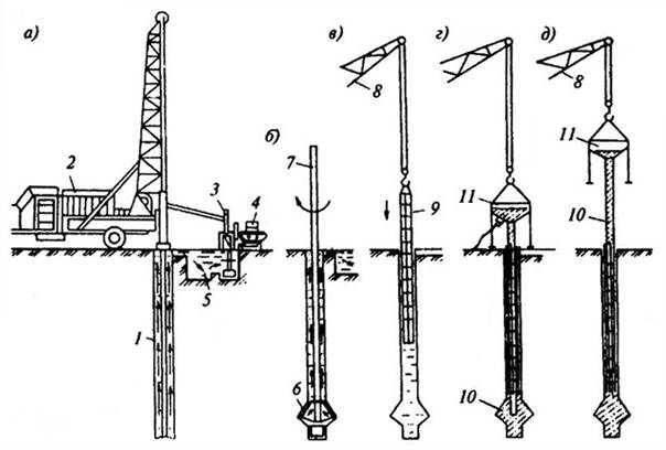
Well formation schemes for stuffed piles are shown in 10.1. As can be seen from the diagram, the installation of stuffed piles can be divided into six main groups. The first three groups include those types of stuffed piles, for the construction of which wells are formed by drilling. These groups have received the general name of bored-stuffed piles.
Three groups of stuffed piles, for which wells are drilled, do not yet have a unifying name.
Below is a brief description of the six groups of piles, taking into account the methods of their installation.
Group I - piles for which wells are formed by dry drilling without mud and casing pipes: wells are drilled using a rotary or other method without widening the shaft or heel or with widening (camouflage piles, with a drillable heel, radial); wells are formed with a leader drill hole, followed by an increase in their diameter to a given size using an explosion (corrugated piles, etc.); the same, rotary drilling from drilled rocks with the addition of cement (soil concrete piles).
Group II - piles for which wells are formed by rotary
drilling without casing pipes, and concreting is carried out under clay
mortar: up to 1 m in diameter (systems of the NIISP Gosstroy
Ukrainian SSR, etc.); with a diameter of more than 1 m - drilling supports (systems
TsNIIS Mintransstroy, etc.).
Group III - piles for which wells are drilled using
casing pipe, concreting is carried out under the protection of
exponentially extractable pipe: concreting is carried out mechanically
tamping of concrete fed into the well (piles of the system
Strauss, Benoto and others); piles form pneumatic presso
concrete (piles of the Wolfsholtz, Grün, Medvedev,
Bozhenkov and Guzeeva); concreting is carried out by a hydraulic press
pouring concrete (piles of the “Maet-Mikhaelis” system, etc.).
Group IV - piles for which holes in the ground form
stamps and concreting are carried out without casing: piles for which
holes in the ground are punched with cones-stamps (piles of systems
"Compressol", Pangayeva, supports in tamped pits
and etc.); holes in the ground are formed by vibromethod or indentation
niem (cone piles, etc.).
Group V - piles for which wells are formed by driving
in the ground of a massive shell with a removable shoe or opening
swivel tip; concreting is carried out with a gradual
extraction of the shell (piles of the "Simplex", "Abo-Lorenz" systems,
"Franks", frequency-rammed, etc.).
Group VI - piles for which wells form a pile
which in the ground of the metal sheath remaining in the ground: in
soil clog a metal sheath with a core (or without
it), then the core is removed and the shell is filled with concrete
(piles of Stern, Raymond, Monotyub, MacArthur, Wilgel-
mi, Lugi, etc.); massive metal wallpaper hammered into the ground
the spoon is replaced with a thinner one that remains in the ground with subsequent
general concreting (with systems of MacArthur, Western, etc.).
The boundaries between different groups of piles indicated in this classification are conditional and mobile. In practice, stuffed piles of various combined structures are used, and the number of possible combinations is very large. In world and domestic practice, there are up to 190 types of stuffed piles. For example, we assigned camouflage piles to group I (they are described in Chapter 13). The same type of piles are made under the protection of casing pipes (group II), in wells formed by shell driving (group V). In this case, preference was given to group I for methodological reasons - as the simplest way to install camouflage piles.
The choice of the method of installing stuffed piles, which depends on many factors, is primarily influenced by the geological and hydrogeological conditions of the construction site. Deciding on the application bored piles or piles for which wells are driven by driving, it should be borne in mind that in the case of the installation of piled piles of groups IV, V and VI, the near-pile soil is compacted, as a result of which the bearing capacity of such piles becomes close to the bearing capacity of driven piles. "
The designs of currently common bored piles of groups I, II and III are expedient in that they allow the use of piles of large diameters and facilitate the installation of a widened heel. Ultimately, it is possible to manufacture stuffed piles of these groups with a bearing capacity that significantly exceeds the bearing capacity of driven and stuffed piles of groups IV-VI.
Modern technology production of bored piles with the help of complex units makes it possible to arrange them with a widened heel. Therefore, in the future, individual methods of manufacturing bored piles, both with and without a widened heel, that have entered into construction practice, will be considered.
§ 3. Methods for arranging a broadened heel
To increase the bearing capacity of bored piles, in many cases it is advisable to increase their bearing area.
Below are six main ways to construct widened pile heels: 1) by various methods of mechanical compaction of concrete in wells; 2) vibro-impact method, production of stuffed piles; 3) by pneumatic pressing of the stuffed pile shaft. This method is applicable for the installation of Wolf-Sholtz, Bozhenkov and Guzeev, Grun piles, i.e. for type II piles; 4) special drilling mechanisms, with the help of which a spherical space with a diameter significantly exceeding the diameter of the well is formed below the bottom of the well. The formed spherical cavity is filled with concrete; 5) using a camouflage explosion. An explosive charge is lowered into the well, then part of it is filled with plastic or cast concrete, after which an explosion is performed. The cavity below the bottom of the well, formed after the explosion, is immediately filled with concrete coming from the wellbore; 6) using an electromechanical or electro-hydraulic device that pushes (crushes) the soil at the base of the well.
The bases can be broadened by separate or complex mechanisms, which form a broadened heel during the drilling of a well. For example, a well-known Benoto pile assembly can drill wells under casing and, if necessary, widen the base of the pile.
When describing the technology of arranging piles with such units, the arrangement of the shaft and the widened heel are considered together.
§ four. Design features pile foundations
The peculiarities of stuffed piles are that each pile can take significant concentrated loads - up to 1000 tons, which makes it possible in some cases to refuse to install a grillage, which is necessary for any other solution, or to significantly reduce its size. Stuffed piles are especially advisable to arrange under buildings with very large loads on their foundations.
in workshops and industrial buildings point loads at metallurgy facilities reach 4,000 tons, and in the main buildings of power plants - 10,000 tons. Loads per column will be 400-600 tons in a number of industries are approximately 30% - In residential and civil buildings with a height of 16-25 floors, columns perceive loads 600 tons and more. At the same time, the simplest stuffed piles can be arranged for small loads, which is important in rural construction.
Stuffed piles can be easily modified to suit different soil conditions, patterns, loads, etc. Moreover, camouflage, pneumatic and hydraulic piles can be resized during construction in inverse proportion to the bearing capacity of the soil.
In order to ensure the reliable operation of the structures of the above-ground parts of buildings and at the same time the effective use of the bearing capacity of materials of pile foundations, when linking projects, it is possible to change the pitch of piles, the cross section of their shafts (using a set of working bodies of various diameters), the amount of widening, drilling depth, brand concrete, etc.
The main advantage of stuffed piles lies in the insignificant absolute and relative settlements of structures. In addition, the creation of the "pile-column" node, which is difficult when constructing foundations on driven piles, is easily implemented in any type of stuffed piles. The top of a stuffed pile and, accordingly, a grillage (monolithic or prefabricated) can be placed at any level without additional transition elements, which is difficult with driven piles.
The large bearing capacity of stuffed piles often makes it possible to get by with a single pile instead of a bush of driven piles and the grillage necessary for it, and to carry out installation work on an unbroken surface. It is also important that with the use of stuffed piles, the number of standard sizes of prefabricated elements is significantly reduced.
The stuffed pile consists of the following elements: the shaft (body) of the pile, the head and the heel, which may end in a broadened base.
The pile shaft, as noted above, can be made from various homogeneous materials of a monolithic or prefabricated monolithic structure. In domestic practice, the latter are usually made of reinforced concrete in the form of racks-columns of a given length, immersed at design marks and ending in a monolithic broadened heel. With a significant length of piles, large
loads on them or in adverse hydrogeological conditions, piles with shell shafts made of metal, reinforced concrete pipes or rings are used. In foreign practice, mixed
structures are most often used in the form of corrugated steel shells filled with concrete (Raymond piles).
The shafts of stuffed piles are reinforced mainly in the heads. Continuous reinforcement of the shafts is only necessary to absorb significant bending forces, as well as when using stuffed piles as anchors. This is one of the differences between driven piles and driven piles, which need to be reinforced to ensure the safety of piles during transportation and in the process of driving.
The possibility of a significant increase in the heel of stuffed piles
one of their main advantages and sources of efficiency. The diameter of their broadening is usually 2.5-3.5 times larger than the diameter of the trunk, which corresponds to a 7-12-fold increase in the area of bearing on the ground. The expansion limits and foot geometry depend on the types of piles to be driven and the equipment used (10.2).
It is also possible to increase the bearing capacity of relatively short stuffed piles by installing several extensions on the shaft (10.3).
Studies of the bearing capacity of stuffed piles were carried out by the laboratory of foundations and foundations Uralpromstroy-NIIproekt. The data of these tests with a different number of pile widenings are given in Table. 10.1.
As can be seen from the above data, it is more than twice as economical to provide a unit of pile bearing capacity by widening as compared to the same result obtained by increasing the diameter and depth of the pile. It is also advisable to arrange broadening from the point of view of saving labor costs and materials (Table 10.3).
These data show the possibility of reducing the specific consumption of concrete when making widenings on pile shafts.
Depending on the design of the structure, based on piles, and the load, the structures of the heads are provided in two versions: under the grillage (concrete platform, reinforcing outlets) and under the columns - a pin mounting table or a glass.
10.4 shows the main designs of the heads of stuffed piles for 10.5 - possible options joints of piles with prefabricated rand beams. The designs of monolithic grillages on stuffed piles are no different from their similar solutions on driven piles.
In the elements of prefabricated grillages - rand beams - junction nodes (joints) can be prefabricated and prefabricated-monolithic. In a prefabricated joint, embedded parts are welded using overhead plates or reinforcing outlets are made that fix the position of the rand beam through special channels; in a prefabricated-monolithic joint, reinforcing outlets are used.
The characteristic designs of foundations on stuffed piles are described below. Examples of such foundations are the underground parts of houses with a technical underground. They are arranged for basement-free buildings with longitudinal load-bearing walls, transverse load-bearing partitions and frame.
A basementless house made of short stuffed piles, built in Kyiv at the suggestion of D. A. Romanov, was the first building on such piles in domestic practice. Under each transverse load-bearing partition wall, two prefabricated rand beams were provided, each of them supported on four piles with camouflage widening. Prefabricated rand beams are connected to the pile heads with reinforcing bars.
10.6 shows the plan and structures of the underground part of a five-story house on stuffed piles built in Moscow. The pile heads are connected by a precast concrete grillage.
All piles, designed for a load of 50 tons, have the same size and differ only in the design of embedded elements. The pile diameter is 40 cm, the widening is 100 cm, the length of the pile with the heel is 3 m. In total, 111 piles were arranged under the three-section five-story building.
The project provided for three options for the construction of the underground part using camouflage piles: prefabricated posts and rand beams; piles and beams are monolithic; mixed - monolithic piles and prefabricated rand beams.
The prefabricated reinforced concrete grillage is located at marks in two levels: under the outer walls directly along the piles, and under the longitudinal wall it is raised to the level of -0.73. The entire grillage was assembled from 49 random beams of five grades. To connect them with piles in the beams, vertical channels with a section of 80X80 mm are provided. After installation, the channels were filled with mortar, and the beams were connected by welding.
In order to minimize earthworks, the level of the floor of the technical underground was raised to -1.4 m throughout the basement, except for the premises of the elevator point and the shield room, where the soil is developed to the level of -2.6 m. The height of the underground intended for communications is 1 ,1-1.2 m.
With this solution, manual earthworks for backfilling, sealing the sinuses inside and outside the building, and planning floors in the technical underground are reduced to nothing. Foundation works (drilling, installation, etc.) are carried out from an unloosened surface, which creates favorable conditions, especially when working in clay soils.
A slightly different constructive solution has a foundation on camouflage piles of a house of the 1-480 series .. Piles are used here of two types with the same laying depth - 2.5 m and differ from each other in the size of the camouflage vimipe-ni "I (100 and 120 cm).
The arrangement of piles in the plan is done differently than in a residential building of series 1-515. Piles and rand beams are placed in strict accordance with the construction of the above-ground part of the building at the points of intersection of the axes. A second type of camouflage widening was introduced to evenly distribute the loads on the piles. The pitches of piles for external and internal longitudinal walls are 2.6 and 3.2 m, for transverse walls - 2.5 m.
In the project series 1-515, the grillage along axis B is raised to the level of the bottom of the floor, in contrast to the projects described above. Although the technology for the production of works is somewhat complicated, however, with such a design, prefabricated reinforced concrete is consumed less, since the bottom of the middle longitudinal wall up to the ceiling mark is replaced by piles.
In the foundation of the described construction of the house, the grillage is prefabricated-monolithic. The rand beams were interconnected by welding the reinforcement protrusions, to which two rods emerging from the pile were welded. Then the joint was promised. Prefabricated-monolithic grillage is tougher than prefabricated; it more easily perceives possible uneven stresses. The disadvantage of this pairing is its high complexity, especially in winter.
The foundation structure for a frame-panel house can be used for any other frame buildings with loads on the column within the bearing capacity of one pile (10.7). Usually, the foundations for frame houses are made of prefabricated reinforced concrete shoes-pillars and columns with consoles, on which the basement panels rest. There are three types of piles in this project. The pile of type KS-1 for the inner row of columns has a widening of 1.2 m. The top of the pile ends with a mounting table 40x40 cm made of a steel sheet 10 mm thick welded to the outlets of the reinforcing cage. Pile KS-2 for the outer row of columns in accordance with a lower load
has a smaller widening of -90 cm. The widening of the KS-3 pile for balcony posts due to minor loads is taken smaller - 60 cm. Prefabricated columns with a section of 30X20 cm end with mounting tables.
Piles are joined to columns by welding mounting tables. A number of similar buildings built with precast concrete pillars
§ 5. Determination of the bearing capacity of stuffed piles
The bearing capacity of stuffed piles, as well as driven piles, is determined by the smallest value of the bearing capacity obtained on the basis of the following two conditions: the resistance of the pile material and the soil resistance of the pile base.
When calculating the bearing capacity of stuffed piles against the resistance of the material, the design resistance of concrete should be determined taking into account the reducing coefficient of working conditions tg = = 0.85, provided for by SNiP for the design of concrete and reinforced concrete structures for compressed elements concreted in a vertical position. In addition, an additional reduction factor for working conditions is introduced, taking into account the influence of the method of work.
When calculating the bearing capacity of stuffed piles according to formula (10.3), the resistance of sandy soils on the side surface of a pile with a broadened heel is taken into account in the area from the level of the layout to the intersection of the pile shaft with the surface of an imaginary cone (10.9), the generatrix of which is the line touching the border of the widening at an angle " f1°/4 to the pile axis - the averaged (by layers) calculated value of the angle of internal friction of the soil lying within the specified cone.
For all types of stuffed piles, arranged in clay soils (with the exception of piles with a soil core), R is determined from Table. 10.6.
In all calculations, it is assumed that the penetration of a stuffed pile into the ground, taken as a foundation, is not less than its diameter or the diameter of the widening for a pile with a widened heel, but not less than 2 m.
When designing foundations from stuffed piles and pile-pillars minimum dimensions grillages (10.10) are set based on the fact that the minimum distance between the axes of hanging piles without widening should be at least 3d, where d is the diameter of the pile. The clear distances between the shafts of shell piles should be at least 1 m, between the widenings of bored piles and shell piles when they are installed in clay soils of hard and semi-solid consistency - 0.5 m, in other types of non-rocky soils - 1 m.
When choosing a pile foundation system, it should be borne in mind that the bearing capacity of rammed piles with a widened heel is higher than without widening. Therefore, instead of several rows of piles without a widened heel, it is advisable to use one or two rows of piles with a widened heel, which makes it possible to reduce the size of the grillage.
§ 6. Scope of stuffed piles
The type of piles should be chosen based on the specific conditions of the construction site based on the results of a feasibility study of design options for foundations. It must also be borne in mind that each type of pile has its own appropriate area of application. For example, it is impossible to arrange stuffed piles in conditions of aggressive ground or industrial waters, but ready-made piles to be driven into soils with inclusions of stones, boulders, etc.
Bored piles with a diameter of 0.4-1.7 m (with or without a broadened heel) are recommended to be placed under buildings or structures of any purpose with large concentrated vertical and horizontal loads, as well as on sites with difficult geological conditions of construction, in which it is impossible to use driven piles. piles.
It is also advisable to arrange bored piles in the following conditions: in soils with solid inclusions (in the form of the remains of destroyed parts of stone, concrete, reinforced concrete structures, etc.), as well as in the presence of layers of clay soils of a solid consistency, interbedded with pebbles and boulders, which is not allows the use of driven or vibro-immersed piles; on cramped sites where it is difficult to transport and install finished piles; near existing buildings and structures in which unacceptable deformations may occur load-bearing structures when driving or vibrating piles.
Bored piles without fixing the walls of wells are arranged in clay soils of hard, semi-solid and refractory consistency (including clay subsidence and swelling soils), if the groundwater horizon during the construction period is located below the heel of the piles.
When drilling wells in clayey soils of soft-plastic and fluid-plastic consistency, it is recommended to use a clay solution to fix their walls.
In cases where the soil of the construction site is They are water-saturated heterogeneous clays of a fluid consistency with interlayers of sand and sandy loam; it is advisable to use casing pipes to fix the walls of the well during their penetration.
Bored piles, arranged using special machines with fixing the walls of the wells with retrievable (inventory) pipes, are recommended to be used in any soil conditions, especially when the lower ends of the pile will be supported on rocky or other types of dense soils of high bearing capacity (hard clay soils, coarse, dense sands).
An example of the mass use of bored piles in foundation construction is the construction of KamAZ. A feasibility study showed that in the soil conditions of this plant it was expedient to use both driven and bored piles. Here, mainly bored piles were used, the installation of which, in a short time at lower costs compared to driving, provided the front for installation work faster.
For the installation of piles, auger drilling installations were used, with the help of which wells were drilled with a diameter of 0.6-1.2 m and a depth of up to 25 m. The concrete mixture was delivered by concrete trucks, from which it was placed directly into the wells.
As shown by economic calculations, the labor intensity of work on the installation of foundations from bored piles is more than 2 times lower than the labor intensity of work on the installation of columnar foundations.
The experience of mass construction of foundations from bored piles made it possible to create at KamAZ a unified scheme for the construction of a zero cycle without excavation.
The introduction of bored piles raises the construction of the zero cycle to a higher technical level.
Driven piles made by driving retrievable inventory pipes with a shoe left in the ground, or by driving inventory casing pipes and forming a core of densely compacted rigid concrete inside them at the bottom of the pipe. Stuffed piles in punched wells differ from bored piles in a more efficient use of the bearing capacity of soils. It is advisable to use these piles in cases where there are no reinforced concrete piles or when the level of occurrence of dense soils of the bearing layer fluctuates sharply in the area under construction. In the latter case, the use of stuffed piles makes it possible to avoid unproductive consumption of reinforced concrete as a result of underloading of a part of the driven piles to the design marks and felling their upper ends.
Stuffed piles are arranged directly at the construction site, at the site of the future building or structure.
Depending on the method of arranging wells and laying concrete in them, there are two types of stuffed piles:
a) piles for which wells are formed by drilling; In this case, there can be two ways of laying concrete:
b) piles for which holes in the ground are formed by plunging a closed-end steel pipe and the concrete is compacted by frequent tamping using hammer blows on the pipe (often tamped piles) or using vibration from a vibratory driver.
Wall mounting can be done:
1. using a casing pipe (dry method) extracted from the well as concrete is placed, and
Dry way applicable in stable soils; its technology is as follows (Fig. VI.10). Rotary drilling in the ground drills a well of the required diameter and to a given depth. After the well bottom reaches the design mark, if necessary, the lower part of the well is widened with special expanders. After the well is accepted, according to the act, a reinforcing cage is mounted in it and concreted using the vertically moving pipe (VPT) method. As the concrete is laid, the concrete pipe is removed from the well. The concrete mixture is compacted with the help of vibrators mounted on the receiving funnel of the concrete pipe.
2. no casing (wet method) when concrete is laid using a slurry (called bentonite);
Without casing it is also possible to arrange bored piles (Fig. VI. 11). Here, as a formwork that prevents the collapse of the walls of the well, a clay solution is used, which enters the well through a hollow drill rod. Due to the hydrostatic pressure exerted by this solution, the density of which is 1.2 ... 1.3 g / cm 3, piles are arranged without casing pipes. The clay solution is prepared at the work site mainly from bentonite clays, and as it is drilled, it is injected into the well. Rising along the well along its walls, the clay solution enters the sump, from where it is returned by the pump to the drill rod for further circulation. Then a reinforcing cage is installed in the well. The concrete mixture is fed using a vibrobunker with a concrete pipe, which is lowered into the well. The vibrated concrete mixture, entering the well, displaces the clay solution. As the well is filled with concrete mix, the concrete conduit is removed.

The considered method of fastening the walls of wells is the simplest. However, it is not reliable enough and is very laborious in the production of work in winter.
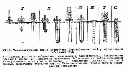
The device of bored piles with fastening of the walls of wells with casing pipes(Fig. VI. 12) is possible in any geological and hydrogeological conditions. Casing pipes can be left in the ground or removed from wells during the pile making process (inventory pipes). Sections of casing pipes are usually connected by joints of a special design or by welding. Casing pipes are immersed in the process of drilling a well with hydraulic jacks, as well as by driving a pipe into the ground or by vibration immersion. Wells are drilled in a rotary or percussive way with special installations.
At shock drilling, the casing pipe is immersed in the ground as the well is developed. At the same time, individual sections of casing pipes are increased as necessary.
At rotational In the drilling method, a leader well is first drilled to the length of the casing pipe section, after which the casing pipe is lowered into the well. Then the next section of the well is drilled, after which the next section of the casing pipe is built up and immersed in the well. These operations are repeated until the well is drilled to the design level.
After cleaning the bottomhole and installing a reinforcing cage in the well, the well is concreted using the VPT method. As the well is filled with concrete mixture, the inventory casing is removed. At the same time, a special system of jacks mounted on the unit imparts a reciprocating and rotational movement to the casing pipe, additionally compacting the concrete mixture. Upon completion of concreting, the pile head is molded in a special inventory jig.
Stuffed piles are often made with a broadened lower part - the fifth. The widening is done with special drills, as well as by exploding an explosive (camouflage piles). The widening is done to increase the bearing capacity of the pile.
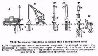
Camouflage piles are made as follows (Fig. VI. 13). First, a well is drilled, a casing pipe is lowered into it. An explosive is placed at the bottom of the well, which is covered from above with a layer of 0.7 ... 1 m of cast concrete. The resulting concrete plug is needed so that the energy of the explosion is directed to the formation of a cavity in the ground. The cavity is then filled with concrete and the pile is concreted in the usual way.
Often-tamped piles are arranged by driving casing pipes resting on a metal tip. Then, in the cavity formed by the casing, a reinforced (or non-reinforced) pile is arranged.
Often-tamped piles (Fig. VI. 14) are arranged using a special pile driver. A hammer and a casing are lifted onto the headframe with a winch, which has a head in the upper part. A metal shoe with a resin rope is placed on the lower end of the casing pipe to prevent water from entering the pipe. Under the action of hammer blows, the casing pipe is immersed to the design mark. While plunging, the pipe pushes the soil particles apart and compacts it. Then the hammer is raised and the reinforcing cage is lowered into the pipe cavity (if the piles are reinforced). Concrete mixture with a cone draft of 8...10 cm is fed from the vibratory tub through a funnel into the cavity of the casing pipe.
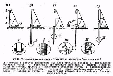
In parallel with the laying of the mixture, the casing pipe is removed (pulled out) by a small amount and again upset with a hammer to compact the concrete, while the metal shoe remains at the base of the pile.
AT last years began to arrange soil-concrete piles, for which they use crane-drilling machines with a hollow drill rod, which has a mixing drill with cutting and mixing blades at the end. A water-cement slurry produced in a mortar mixer is pumped through the rods with a mortar pump. The mixing drill, during reverse rotation and extraction, compacts the soil saturated with water-cement emulsion in layers. As a result, a soil-concrete pile is formed, made on site without excavation. On fig. U1.15 shows a schematic diagram of the arrangement of soil-filled piles.
TECHNOLOGY of stuffed piles
Issues under consideration:
10.1. Stuffed pile technology.
10.2. Grilling device technology.
10.3. Device pile foundations in winter time.
10.4. Quality control and acceptance of pile foundations. Occupational safety in the production of pile work.
Topics of control testing questions:
1. The main types of stuffed piles.
2. Technology of the device of bored piles.
3. Dry pile technology.
4. Installation of piles using clay mortar.
5. Installation of piles with fastening of the walls.
6. The device of bored piles with a wide heel.
7. How are pipe concrete piles made?
8. How are pneumatic piles made?
9. How are vibro-rammed piles made?
10. How are frequency-rammed piles made?
11. How are Franchi piles made?
12. How are rammed sand piles made?
13. How are soil-concrete piles made?
14. Technological sequence of grillages.
15. Features of the arrangement of pile foundations in winter.
16. How is the quality control of pile work carried out?
17. How is the bearing capacity of piles controlled?
18. How is failure determined by failure meters?
19. How is the acceptance and delivery of pile foundations carried out?
20. What are the main requirements for labor protection when performing pile work?
Stuffed pile technology
Stuffed piles are arranged at the site of their design position by laying (stuffing) a concrete mixture or sand (soil) into cavities (wells) formed in the soil. Piles are often made with a broadened lower part - the fifth. Widening is obtained by drilling the soil with special drills, bursting the soil with reinforced tamping of the concrete mixture in the lower part of the well, or by detonating an explosive charge.
Currently applied a large number of solutions for such piles. Their main advantages: the possibility of manufacturing any length; the absence of significant dynamic impacts during the installation of piles; applicability in cramped conditions; applicability when strengthening existing foundations.
Depending on the methods of creating a cavity in the soil and the methods of laying and compacting the stuffing material, piles are divided into bored, pneumatic, vibro-rammed, frequency-rammed, Franky, sand, soil-concrete and screw piles. The length of the piles reaches 20 ... 30 m with a diameter of 50 ... 150 cm. Piles manufactured using equipment from Kato, Benoto, Liebherr can have a diameter of up to 3.5 m, a depth of up to 60 m, a bearing capacity of up to 500 tons .
Bored piles. A characteristic feature of the device of bored piles is the preliminary drilling of wells to a given mark and the subsequent formation of the pile shaft.
The very first in our country, on the basis of which all existing types of bored piles are used, are Strauss piles, which were proposed in 1899. Strauss piles are made with a diameter of 30 ... 40 cm and a length of up to 10 ... 12 m. Piles of this type poorly transmit force to the ground through the side surface and work as piles-racks.
Production of stuffed piles Strauss includes the following operations: drilling a well; lowering the casing pipe into the well; extraction of crumbling soil from the well; filling the well with concrete in separate portions; tamping of concrete with these portions; gradual removal of the casing.
The well is buried in the base layer by at least 0.2 ... 0.5 m, depending on its density. The wells are filled with layers 0.8…1 m high. Each layer is compacted with rammers while removing the casing pipe. In this case, it is necessary to ensure that the concrete layer from the bottom of the casing has a height of 0.3 ... 0.4 m.
The casing is removed using a pile driver, a crane or a tripod with a winch.
As a rule, Strauss piles are reinforced only in the upper part to a height of 1.5 ... 2 m to connect the pile with the grillage.
Depending on the soil conditions, bored piles are arranged in one of the following three ways: dry (without fixing the walls of the wells), using a clay solution (to prevent the collapse of the walls of the well) and fixing the well with a casing pipe.
Dry way applicable in stable soils (subsidence and clayey solid semi-solid and refractory consistency), which can hold the walls of the well (Fig. 10.1). A well of the required diameter is drilled by rotary drilling in the ground to a predetermined depth. After acceptance of the well in the prescribed manner, if necessary, a reinforcing cage is mounted in it and concreted using the vertically moving pipe method.
Rice. 10.1. Technological scheme of the device of bored piles in a dry way:
a) well drilling; b) drilling out a widened cavity; in G- installation of a concrete pipe with a vibrobunker; d) concreting of the well using the vertically displaced pipe (VPT) method; e) lifting concrete pipe;
1 – drilling rig; 2 - drive; 3 - screw working body; 4 - well;
5 - expander; 6 - broadened cavity; 7 - reinforcing cage; 8 - jib crane;
9 - conductor-pipe; 10 – vibrobunker; 11 - concrete pipe; 12 - tub
with concrete mixture; 13 - widened pile foot
Concrete pipes used in construction, as a rule, consist of separate sections and have joints that allow you to quickly and reliably connect pipes. Sections of concrete pipes 2.4 ... 6 m long at the joints are fastened with bolts or interlocks, a receiving hopper is attached to the first section, through which the concrete mixture is fed into the pipe. A concrete pipe is lowered into the well to the very bottom, concrete mixture is fed into the receiving funnel from a concrete mixer truck or using a special loading hopper, vibrators are fixed on the same funnel, which compact the laid concrete mixture. As the mixture is laid, the concrete pipe is removed from the well. At the end of the concreting of the well, the pile head is molded in a special inventory jig, in winter time it is additionally reliably protected.
Using the dry method, according to the considered technology, bored piles with a diameter of 400 to 1200 mm are produced, the length of the piles reaches 30 m.
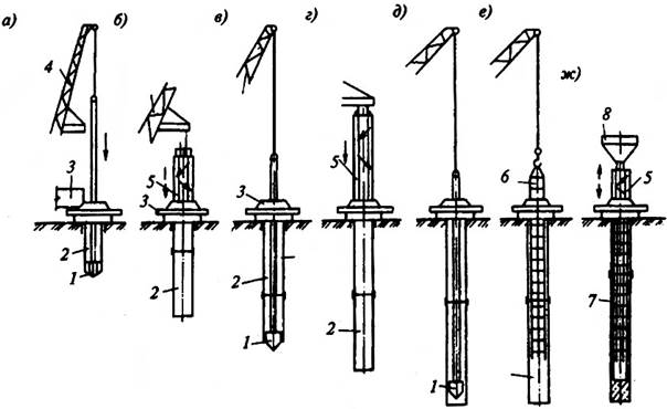
Application of clay solution. The installation of bored piles in weak water-saturated soils requires increased labor costs, which is due to the need to fasten the walls of the well to protect them from collapse. In such unstable soils, to prevent the collapse of the walls of wells, a saturated clay solution of bentonite clays with a density of 1.15 ... well keeps the walls of wells from collapse. This is also facilitated by the formation of a clay cake on the walls of the well due to the penetration of the solution into the soil (Fig. 10.2).
Wells are drilled in a rotary way. However, when driving through rock inclusions and layers, replaceable impact-type working bodies (grabs, chisels) are used.
Clay mud is prepared at the work site and, as drilling progresses, it is fed into the well through a hollow drill rod under pressure. As drilling proceeds, the solution under hydrostatic pressure from the place of drilling, encountering soil resistance, begins to rise up along the walls of the well, carrying out the soil destroyed by the drills, and coming to the surface, enters the sump sump, from where it is again pumped into the well for further circulation.
The clay solution, which is under pressure in the well, cements the soil of the walls, thereby preventing the penetration of water, which makes it possible to exclude the use of casing pipes. After the drilling of the well is completed, if necessary, a reinforcing cage is installed in it, the concrete mixture from the vibrobunker through the concrete-cast pipe falls to the bottom of the well, rising up, the concrete mixture displaces the clay solution. As the well is filled with concrete mix, the concrete pipeline is lifted.
Rice. 10.2. Technological scheme of the device of bored piles
under clay mortar: a) well drilling; b) the device of the expanded cavity; in- installation of a reinforcing cage; G- installation of a vibrobunker with a concrete pipe;
d) concreting of the well by the VPT method; 1 - well; 2 - drilling rig.
3 - pump; 4 - clay mixer; 5 - pit for clay solution; 6 - expander;
7 - rod; 8 - jib crane; 9 - reinforcing cage; 10 - concrete pipe;
11 - vibrobunker
The device of bored piles with fastening of the walls wells with casing pipes is possible in any geological and hydrogeological conditions (Fig. 10.3). Casing pipes can be left in the ground or removed from wells during the production of piles (inventory pipes). Sections of casing pipes are usually connected by joints of a special design or by welding. Casing pipes are immersed in the process of drilling a well with hydraulic jacks, as well as by driving a pipe into the ground or by vibration immersion. Wells are drilled in a rotary or percussive way with special installations.
In percussion drilling, the casing is driven into the ground as the well is developed. At the same time, individual sections of casing pipes are increased as necessary.
In the rotary drilling method, a leader well is first drilled to the length of the casing pipe section, after which the casing pipe is lowered into the well. Then the next section of the well is drilled, after which the next section of the casing pipe is built up and immersed in the well. These operations are repeated until the well is drilled to the design mark.
Rice. 10.3. Technological scheme of the device of bored piles
using casing pipes: a- installation of a conductor and drilling a well;
b) immersion of the casing; in) well drilling; G) extension of the next section of the casing; d) bottom hole cleaning; e- installation of a reinforcing cage; and- filling the well with concrete mix and extracting the casing; 1 - working body for drilling a well; 2 - well; 3 - conductor; 4 – drilling rig;
5 - casing pipe; 6 - reinforcing cage; 7 - concrete pipe; 8 - vibrobunker
After cleaning the bottomhole and installing a reinforcing cage in the well, the well is concreted using the vertically movable pipe (VPT) method. As the well is filled with concrete mixture, the inventory casing is removed. At the same time, a special system of jacks mounted on the unit imparts a reciprocating and semi-rotary movement to the casing pipe, additionally compacting the concrete mix. At the end of the concreting of the well, the pile head is molded in a special inventory jig.
Bored piles with a wide heel. The diameter of such piles is 0.6 ... 2.0 m, the length is 14 ... 50 m. There are three ways to widen the pile.
First way- soil bursting by reinforced tamping of the concrete mixture in the lower part of the well, when it is impossible to assess the quality of work, the shape (what the widening heel has become), how much the concrete has mixed with the soil and what is its bearing capacity.
 At second way the well is drilled with a machine tool that has a special device in the form of a drop-down knife on the drill string to form a broadening of the well with a diameter of up to 3 m (Fig. 10.4). The knife is opened by a hydraulic mechanism controlled from the ground. When the rod rotates, the knives cut off the soil, which falls into the bucket located above the expander. After several operations of cutting the soil with knives and extracting it to the surface, a broadened cavity is formed in the soil. A clay solution of bentonite clays is fed into the well, which continuously circulates and ensures the stability of the well walls.
With the device of broadening, the cavity is drilled out simultaneously with the supply of fresh clay solution to the well until the solution contaminated with soil is completely replaced. After completion of drilling of the well to the design depth, the drill string with the reamer is removed, and a reinforcing cage is installed in the well. Concreting is carried out using the method of a vertically moving pipe, when a concrete mixture is simultaneously fed into the pipe and lifted. The concrete mixture, in contact with a viscous clay solution, does not reduce its strength, the cement binder is not washed out of the mixture. The concrete mixture squeezes the slurry up the pipe and through the gap between the pipe and the well. The lower end of the concrete pipe must be permanently buried in the concrete mixture to a depth of about 2 m; concreting is carried out continuously so that there are no layers of clay solution in the concrete.
Third way for the device of broadening in the foundations of piles - explosive. To do this, a casing pipe is installed in the drilled well so that its lower end does not reach the bottom of the well by 1.2 ... 1.5 m, that is, it is outside the scope of the camouflage explosion. An explosive charge of the estimated mass is lowered into the casing pipe to the bottom of the well and the conductors are led from the detonator to the blasting machine. The pipe is filled with a concrete mix and an explosion is made. The energy of the explosion compacts the soil and creates a spherical cavity, which is immediately filled with concrete mix from the casing. The well is finally filled in the manner described above.
Bored pile with shoe. The peculiarity of the method is that a casing pipe is lowered into the drilled well, having a freely supported cast-iron shoe at the end, which is left in the ground after the casing pipe is immersed to the required depth. By portionwise loading the concrete mixture, regularly compacting it and gradually removing the pipe from the well, a ready-made stuffed concrete pile is obtained.
Pipe concrete piles. The fundamental difference of the method is that the casing pipe up to 40...50 m long has a rigidly fixed shoe in the lower part. After reaching the bottom of the well, the pipe remains there, is not removed, but is filled with a concrete mixture.
Pneumatic piles used in the construction of foundations with a large influx of water, which complicates the construction of bored piles. In this case, the piles are made using compressed air using special equipment - an apparatus for locking the concrete mixture when it is fed into the casing. With the help of this apparatus, a certain pressure of compressed air is maintained in the well, which compresses the concrete mixture.
The use of compressed air allows you to remove groundwater from the casing pipe before concreting, which ensures high quality concrete, and facilitate the lifting of the casing pipe during concreting.
The concrete mixture is fed into the well in portions, with the first portion filling the pipe by no more than 1.5 ... 2 m. Subsequent portions of the mixture are increased. Pneumatic piles can be reinforced for the entire length or only in the upper part. In the first case, a prefabricated reinforcing cage is installed in the casing pipe before the pile is concreted, in the second case, during the concreting process.
Stuffed piles of any type should be concreted without interruption. When the piles are located one from the other by less than 1.5 m, they are performed through one, so as not to damage the newly concreted ones. Missed wells are concreted during the second sinking of the concrete casting plant, after the previously concreted piles are set with sufficient strength and bearing capacity. This sequence of work provides for the protection of both finished wells and freshly concreted piles from damage.
Bored piles have a number of disadvantages that hinder their wider application. Such disadvantages include a small specific bearing capacity, high labor intensity of drilling operations, the need to fix wells in unstable soils, the difficulty of concreting piles in water-saturated soils, and the difficulty of controlling the quality of piles. In our country, bored piles are made with a diameter of 880 ... 1200 mm, up to 35 m long. For the installation of bored piles, cast concrete mix with a cone draft of 16 ... 20 cm is used.
Vibrorammed piles are used in dry cohesive soils, in which a concrete mixture can be laid in an open well 6 m deep (Fig. 10.5).
Rice. 10.5. Technological scheme of the installation of vibro-rammed piles:
a) well formation, b) laying the first portion of the concrete mixture, in) seal
concrete mixture with a tamper bar rigidly connected to a vibratory driver,
G) laying and compaction of subsequent layers of concrete mix, d) removal of the casing pipe and installation of the reinforcing cage in the pile head
Such piles are arranged as follows. A steel casing pipe with a removable reinforced concrete shoe at the end is immersed into the soil using a vibratory driver suspended from an excavator.
After the pipe is immersed, the vibrator is removed and the inner cavity of the pipe is filled to 0.8 ... 1 m with a concrete mixture. With the help of a tamper bar suspended from a vibratory driver, the mixture is rammed, as a result of which it, together with the shoe, is pressed into the ground, forming a broadened heel. After filling the casing pipe with a concrete mixture, it is removed from the soil using an excavator with the vibratory driver running. After removing the pipe, a reinforcing cage is installed to connect the pile head with a reinforced concrete grillage.
Often-tamped piles have become widespread in construction (Fig. 10.6). A characteristic technological feature of the manufacture of frequency-rammed piles is that the casing pipe is immersed by driving with a special pile driver, with the help of which the concrete mixture is also compacted and the casing pipe is removed.
Rice. 10.6. Technological scheme of the device of frequency-rammed piles:
a) lifting the casing pipe and hammer into the working position; b) casing dip
pipes; in- installation of a reinforcing cage; G) supply of concrete mixture into the pipe cavity;
d- removal of the casing pipe with simultaneous compaction of the concrete mixture;
1 - pile driver; 2 - double action hammer; 3 - winch; 4 - casing pipe;
5 - reinforcing cage; 6 - vibrobot; 7 - receiving funnel
Piles are made up to 20 m long and 0.3 ... 0.6 m in diameter.
When immersed, the casing pipe is closed from below with a cast iron shoe, which remains in the ground and serves as the base of the pile.
The lower (ramming) end of the pipe has a thickening. After driving the pipe to the design mark, the hammer is raised, a reinforcing cage is lowered into the pipe, and a receiving funnel is installed at the mouth of the pipe, through which the concrete mixture is fed. The pipe is filled with concrete mixture in portions in two or three steps. The hammer is connected to the casing using a special traction structure (earrings) and produces frequent blows up and down. At the same time, from each blow upwards, the pipe is removed by 3 ... 4 cm, and from a downward blow it plunges by 1.5 ...
The extraction of the pipe should take place in such a way that at any time a layer of concrete 1.5 ... 2 m high remains above its lower end. The concrete mixture must have a draft of the cone 8 ... 10 cm. The volume of the first portion of the mixture should not exceed 0.6 of the length of the pipe and 1 m 3. When the pipe being removed approaches the surface, the last portion of the concrete mixture is loaded with a layer of sand with a volume of 0.25 ... 0.3 m 3.
For the installation of frequency-rammed piles, a special pile driver with a double-acting hammer with automatic steam distribution is used.
Piles Franks. Manufactured as follows.
About 0.2 m 3 of hard concrete mixture is poured into the casing pipe installed on the ground and strongly compacted with a special rammer. The resulting concrete plug is immersed using a pile driver along with the pipe. After the pipe is immersed to the design mark, 0.5 m 3 of concrete mixture is lowered into it. With hammer blows, the concrete plug is knocked out of the pipe, and a widened pile foot is formed from it. Then the pipe is filled with individual portions of the concrete mixture, which are compacted by hammer blows on the pipe. In this case, the top of the concrete in the pipe should be higher than the bottom of the casing when it rises by 0.2 ... 0.4 m.
The extracted pipe is used for stuffing the next pile.
Stuffed sand ( ground) piles used to increase the bearing capacity of weak, loose soils (Fig. 10.7). The manufacturing technology of such piles is as follows. By driving or vibrating, the casing pipe is immersed in the ground. When driving with headstock, the casing pipe has a steel or cast iron shoe at the end, which remains in the ground. When using vibrators, the casing pipe has a drop-down four-lobed tip in the lower part. After immersion to the design depth, the pipe is filled with sand or a sand-gravel mixture.
When using vibratory hammers, sand or a mixture is poured with water and subjected to vibration, while removing the casing. When removing the pipe, the shoe petals open and the sand (mixture), compacting, fills the well.
For compaction, ramming is also used with the help of light pile drivers. In this case, backfilling and compaction of sand or mixtures are carried out in layers with simultaneous removal of the casing.
Additional and effective compaction can be achieved by flooding the well with water. Pipes with a diameter of 32 ... 50 cm are used; when extracting, there should always be a layer of sand (mixture) in the pipe with a height of 1.0 ... 1.25 m. The method is applicable for wells up to 7 m deep.
Ground concrete piles. Soil-concrete piles have found application, which are arranged using drilling rigs with a hollow drill rod, which has a mixing drill at the end with special blades cutting and simultaneously mixing the mixture. After drilling a well in soft sandy soils to the desired level, a water-cement slurry (mortar) is fed into the hollow rod under pressure from the mortar mixing plant. The drill rod slowly begins to rise upward during reverse rotation, the soil is saturated with cement mortar and additionally compacted with a drill. The result is a cement-sand pile made on site without excavation.
Screwed piles. Often, foundation pits for buried structures have to be built near existing buildings. Driving piles and sheet piles can lead to their deformation due to the resulting dynamic effects. When installing bored piles, where the casing pipe is immersed with advanced soil extraction from the pipe cavity, leakage of the soil mass from under adjacent foundations is possible, which can also lead to deformations of existing buildings. Using the "wall in the ground" method or using a mud solution to immerse pipes leads to an increase in the cost of the project.
In cases of dense buildings, it is advisable to use the method of screwed piles.
The essence of the method is that the metal pipe is not driven into the ground, but screwed. A narrow auger made of reinforcement with a diameter of 10 ... 16 mm is wound onto the pipe at the factory with a pitch of 200 ... 500 mm. Depending on the soil conditions, the pipe can be equipped with a plug with rippers, deaf or lost, which, if necessary, prevent water from entering the pipe body. When screwing the pipe, the surrounding soil is partially compacted, about 15 ... 25% of it is squeezed out.
If the pipe in the lower part is deaf, then after screwing up to the design mark, a reinforcing cage is inserted into it, and it is filled with concrete mix. For pipes with a lost tip, a reinforcing cage is inserted into it, the pipe is filled with concrete, in the process of setting the concrete, the pipe is unscrewed, a shoe remains in the ground, on which the reinforced concrete bored pile rests.
With particularly dense soils, it is possible to pre-drill a well to a slightly shallower depth (up to 1 m) and the diameter of the well should be less than the diameter of the pipe. The diameter of the screwed pipes is 300…500 mm, the length is from 4 to 20 m. It is important that the technology allows to perform work near existing buildings at a height of 5 floors at a distance of about 40 cm, at a higher height - about 70 cm.
Stuffed piles are arranged in place of their future position by filling the drilled wells with a concrete mixture (or sand in the case of the manufacture of soil-sand piles). Stuffed piles have a number of advantages in comparison with other types of piles:
Possibility of manufacturing piles of very large length;
· the absence of significant dynamic impacts on nearby structures during the installation of piles;
applicability in cramped conditions;
Can be used to reinforce existing foundations.
The following types of piles are used:
· Ostrich piles;
bored;
· pneumatic;
· vibrotamped;
· frequency-rammed;
vibrating;
· sandy;
soil filling, etc.
The length of the piles can reach 60 m with a diameter of 50-150 cm, the bearing capacity of an individual pile reaches 500 tons.
The main problem in the installation of stuffed piles is to prevent the collapse of the soil of the walls of the well and the high-quality compaction of the concrete mixture. There are also certain difficulties in the manufacture of stuffed piles at low temperatures.
Depending on the soil conditions, stuffed piles are arranged in one of the following three ways:
without strengthening the walls of the well (dry method);
with the use of clay solution to prevent soil collapse (wet method);
· with fastening of wells by casing pipes.
Dry way.
It is used in stable soils, subsidence and clayey solid, semi-solid and plastic consistency. The technology for arranging such piles is as follows:
a well of the required diameter and to a given depth is drilled in the soil;
the lower part of the well is expanded with the help of special expanders (if necessary);
mount reinforcing cages in the well (if necessary);
Concrete wells using the VPT method.
Concrete pipes consist of separate sections (length 2; 4; 6 m), which allows them to be quickly built up. The concrete mixture is fed into the receiving funnel directly from the mixer truck or using a hopper or bucket. As the concrete mixture is laid, the concrete pipe is removed from the well. The concrete mixture is compacted in the well with the help of vibrators installed on the funnel of the concrete pipe. Piles Ø 400-1200 mm and up to 30 m long are made in this way.
Rice. 6.17. Technological scheme of the device of bored piles in a dry way:
a) - drilling a well; b) - the device of a broadened cavity; c) - installation of a reinforcing cage; d) - installation of a concrete pipe with a vibrobunker; e) - filling the vibrobunker with concrete mix; f) - concreting of the well by the VPT method; g) - insulation of the pile head in winter; 1 - auger drilling rig; 2 - expander; 3 - crane with a lifting capacity of 10-12 tons; 4 - concrete pipe; 5 - loading hopper.
Wet way.
This method with the use of a clay solution of thixotropic clays is used in unstable soils. Clay mud enters the well during drilling through a hollow drill rod. If necessary, a reinforcing cage is installed in the well. Piles are also concreted using the VPT method. The concrete mixture, entering the well, displaces the clay solution, which, coming to the surface, enters the sump sump and, after cleaning, is reused.
This method of strengthening the walls of the well (the diagram is shown in Fig. 6.18.) Is the simplest, but it is not reliable enough and is associated with certain difficulties in the production of work in winter.
Fig.6.18. Technological scheme of the device of bored piles under clay mortar:
a) - drilling a well; b) - the device of a broadened cavity; c) - installation of a reinforcing cage; d) - installation of a concrete pipe with a vibrobunker and a funnel; e) - concreting of the well by the VPT method; f) - insulation of the pile head in winter conditions; 1 - drilling machine; 2 - clay mixer; 3 - pump; 4 - expander; 5 - concrete pipe with a vibrobunker.
The method of arranging stuffed piles with a casing pipe.
This method is applicable in any geological and hydrogeological conditions. Immersion of casing pipes into the ground is carried out by hydraulic jacks, as well as by driving or vibration immersion.
Wells are drilled in a rotary or percussive way with special installations. In percussion drilling, the casing is driven into the ground as the well is developed. At the same time, individual sections of casing pipes are increased as necessary.
In the rotary drilling method, a leader well is first drilled to the length of the casing pipe section, after which the casing pipe is lowered into the well. Then the next section of the well is drilled, after which the next section of the casing pipe is built up and immersed in the well. These operations are repeated until the well is drilled to the design mark. After that, the reinforcing cage is installed (if necessary) and the well is concreted using the VPT method. Casing pipes can be left in the ground, acting as permanent formwork for the piles, or removed from the wells during the pile making process. In the case of removing the casing, a special system of jacks is used that imparts a reciprocating movement to the pipe, which additionally compacts the concrete mixture.
As a variant of this technology, a method is also used in which the casing pipe is immersed to the design mark, after which the soil is extracted from its internal cavity with a vibrating grapple. The layout of piles with a casing pipe is shown in fig. 6.19.
Figure 6.19. Technological scheme of the device of bored piles using casing pipes:
a) - installation of the rotor and drilling of the well with simultaneous immersion of the casing pipe; b) - drilling a well; c) - cleaning the bottom of the well; d) - installation of a reinforcing cage; e) - filling the well with a concrete mixture, removing the casing; f) - formation of the pile head in the inventory conductor.
Consider some types of piles, the most common in construction practice.
Bored piles can be arranged in any of the three ways above. Diagrams of their device are shown in Fig. 6.17; 6.18; 6.19.
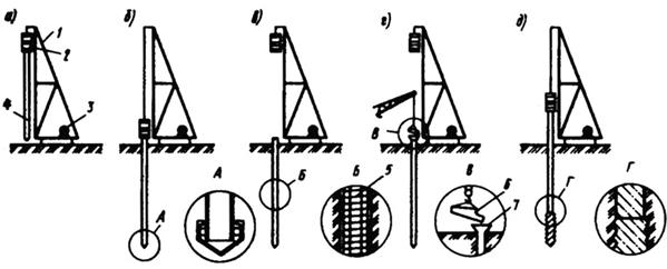
Piles Ostrich- a kind of deep-laid bored piles, the very first to appear in our country (in 1899). The technological process of manufacturing Ostrich piles consists of the following operations:
· a well is drilled to the design level (to a depth of 5-12 m);
casing pipe (Ø25-40 cm) is lowered into the well;
The well is filled with concrete mixture to a depth of about 1 m;
· the concrete mixture is rammed with the simultaneous rise of the casing pipe by 60-70 cm;
A new portion of the concrete mixture is poured, after which the operations are repeated.
The disadvantages of such piles are the inability to control the density and solidity of concrete and the possibility of erosion of the unset concrete mixture by groundwater.
Reinforcement of Ostrich piles is carried out only in the upper part, installing reinforcing bars in freshly laid concrete to a depth of 1.5-2 m to connect the pile with the grillage.
Rice. 6.20. Scheme of the Ostrich pile device:
a) - drilling a well; b) - filling the well with concrete; c) - lifting the casing pipe with concrete tamping; d) - finished pile; 1 - drilling rig; 2 - casing pipe; 3 - VPT; 4 - tamper bar; 5 - freshly laid concrete; 6 - compacted concrete; 7 - reinforcing cage.
Bored piles with a wide heel arranged in three different ways:
Reinforced tamping of a rigid concrete mixture in the lower part of the well (vibrated piles);
using a drilling rig with a special expander;
explosion (camouflage broadening).
Vibrotamped piles used in dry cohesive soils with a depth of 4-6 m. The layout of such piles is shown in Figure 6.21.
Fig. 6.21. Technological scheme for the installation of vibro-rammed piles:
a) - formation of a well; b) - laying the first portion of the concrete mixture; c) - compaction of the concrete mixture with a rammer rod rigidly connected to a vibratory driver; d) - laying and compaction of subsequent layers of concrete mix; e) - extraction of the casing pipe and installation of the reinforcing cage in the pile head.
Drilling rig with special reamer has a drop-down knife on the drill string for the formation of a widening of the well with a diameter of up to 3 m (Fig. 6.22.). The knife is opened by a hydraulic mechanism controlled from the ground. When the drill rod rotates, the knives cut off the soil, which falls into the bucket located under the expander. The formation of a broadening in the heel of the pile allows you to increase its bearing capacity.
Fig.6.22. Drilling a cavity in the ground with a reamer:
1 – drill rod; 2 - levers of the knife mechanism; 3 - cutting knives; 4 - bucket-soil collector; 5 - well; 6 - broadened cavity.
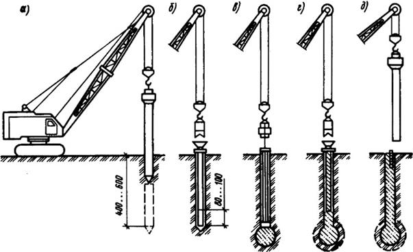
Piles with camouflage widening obtained with the help of an explosion (Fig. 6.23.). A casing pipe is lowered into the drilled well, not reaching 0.5 m to the bottom of the well. An explosive charge is lowered to the bottom of the well, which is covered from above with a concrete mixture by 1.5-2 m. The energy of the explosion compacts the soil and creates a spherical cavity, which is filled with concrete from the casing. After that, in portions, with the necessary compaction, the well is filled with concrete mixture to the top.
Fig. 6.23. Technological scheme for the installation of piles with a camouflage heel:
a) - drilling a well; b) - installation of a casing pipe; c) - laying the explosive charge and the first portion of the concrete mixture; d) - explosion and filling of the camouflage cavity with concrete; e) - installation of the reinforcing cage and post-concreting of the pile.
Pneumatic piles used in the construction of pile foundations in soils with a large influx of water, which complicates the construction of bored piles. In this case, the concrete mixture is placed in the cavity of the casing at a constant high air pressure (0.25-0.3 MPa), which is supplied from the compressor through the receiver. The concrete mixture is fed in small portions through a special device - a lock chamber, which operates on the principle of pneumatic injection units used to transport the concrete mixture. Sluice chambers consist of two sections of pipes connected by flanges, which have upper and lower openings closed by valves. When the mixture is fed through the funnel into the upper chamber, its lower valve is closed; after serving a portion, the upper valve of the upper chamber closes, and the lower one opens, etc. In order to save compressed air, pressurized concrete mixers are used. Reinforce pneumatic piles by immersing reinforcement rods in fresh concrete.
The main disadvantage of driven piles is the overexpenditure of material and labor resources due to cutting pile heads ("priests"), which are formed as a result of unequal failures. The advantage of stuffed piles is the saving of materials. There is also an additional possibility of manufacturing piles of various bearing capacity without a significant change in the technology of work. It is possible to carry out work near buildings and structures, since they are not accompanied by significant dynamic impacts on environment in contrast to the immersion of finished piles.Stuffed piles are made directly on the site in the design position by drilling wells and filling them with concrete mix or other materials.
Initially, rammed concrete piles (Ostrich piles) were installed as a result of drilling wells and laying the concrete mixture with ramming. On this basis, the following types of stuffed piles have been developed and used.
Vibrotamped piles (Fig. 5) are arranged in dry cohesive soils. A casing pipe with a shoe is immersed in the ground, which protects its internal cavity from soil ingress. A portion of the concrete mixture is loaded and rammed using a tamper rod suspended from a vibratory driver; when tamping, a broadened heel of the pile is formed. The subsequent layers are laid and rammed. The casing pipe is removed with the vibrator running and a reinforcing cage is installed for connection with the grillage.
Fig.5. Technological scheme of the installation of vibro-rammed piles
a - well device; b, d - laying concrete mix; c - compaction of the concrete mixture; e - the end of concreting.
Conical piles in a stamped bed (Fig. 6) are obtained in the process of forming a conical well after driving the leader, filling the well with concrete mix (B) or crushed stone (Sh), re-stamping the conical well, installing the reinforcing cage and concreting the pile.
Fig.6. Technological scheme of the installation of stuffed conical piles in a stamped bed
a - the formation of a conical well; b - filling the well with a rigid concrete mixture or crushed stone; c - punching out a conical hole by repeated immersion of the leader; d - installation of a reinforcing cage and concreting of a pile; 1 - base machine; 2 - mast; 3 - falling weight; 4 - conical leader; 5 - hydraulic device for extracting the leader; 6 - hydraulic cylinder; 7 - conical well; 8 - rigid concrete mix or crushed stone; 9 - concrete mixture rammed into the walls of the well; 10 - vibrator; 11 - reinforcing cage.
Frequently compacted piles (Fig. 7) are formed as a result of driving a casing pipe with a metal shoe, installing a reinforcing cage and laying a highly mobile concrete mixture with simultaneous reciprocating hammer blows so that the casing pipe rises by 4 ... 5 cm with each cycle of blows, then dropped by 2-3 cm and thus compacted the concrete mixture. Next, the casing pipe is removed.
Fig.7. Technological scheme of the installation of frequency-rammed piles
a - well device; b - installation of a reinforcing cage; c - laying concrete mix; g - extraction of the casing; e - the lower part of the casing pipe with a lost shoe.
Pneumatic piles are arranged in watered soils, for which, after drilling a well, a reinforcing cage is installed, ground water is displaced with compressed air, the concrete mixture is laid in portions by pneumatic concreting with simultaneous lifting of the casing pipe, in which high blood pressure air (0.2 ... 0.3 MPa).
Sand and soil piles are usually arranged in order to strengthen weak soils (Fig. 8, a). In the manufacture of sand piles, a vibrating method is used, for which a casing pipe with a closed tip is immersed and filled with sand. When lifting the pipe with vibration, the ring falls off the pipe tip (Fig. 8, b), and the sand fills the well.
Fig.8. Schemes of soil piles
a - arrangement of soil-sand piles; b - tip opening; c - production of soil-concrete piles.
If a well (Fig. 8, c) is drilled and then a water-cement slurry is fed into it, then when the drill moves back, the soil is mixed, saturated with a water-cement slurry, and hardens. Such soil-concrete piles are common in Europe due to their sufficient strength and low cost. Options for the use of soil piles are shown in Fig. 9.
Fig.9. Options for using soil piles as
a - strengthening the foundations of the foundations; b - protection of communications from ground water; c - protection against soil collapse; g - sheet piling.
Bored piles are the most widely used due to their cost-effectiveness and high bearing capacity. Piles can be concreted without a casing pipe: in an open well ("dry" method) or with filling the well with clay mortar; as well as with a casing pipe.
The well is arranged by ramming, rotary or impact drilling.
The main difference between machines for arranging wells is the method of extracting soil from a well (Fig. 10). When punching a well with a leader punch or casing, the soil is not extracted. The auger drill raises the soil upward due to the rotation of the screw auger. In the case of using bucket and clamshell drills, the soil is lifted in closed drilling shells.
Fig.10. Well construction methods using
a - slaughtered leader; b - auger drill; c - clamshell drill; g - bucket drill.
With the extraction of soil, wells with a diameter of up to 2 m can be drilled to a depth of 40 m. For drilling heavy rocks to a greater depth, pipe twisting installations can be used.
The dry method of arranging bored piles without a casing pipe can be used in stable soils according to the following technological scheme (Fig. 11, a): I - drilling a well; // - removal of the conductor; ///- installation of reinforcing cage; IV - installation of the bunker; V - laying concrete mixture with compaction by a vibrator installed on a concrete pipe; VI - removal of the bunker; VII - concreting of the pile head.
Fig.11. Technological scheme for the installation of bored piles "dry" (a) and under mud (b)
1 - well; 2 - drilling unit; 3 - pumping unit; 4 - clay mixer; 5 - sump; 6 - expander; 7 - conductor; 8 - reinforcement cage; 9 - pulp container; 10 - concrete pipe; 11 - valve; 12 - concrete pipeline sleeve; 13, 14 - head and body of the pile.
The concrete pipe is removed from the well as the concrete mixture is laid.
When installing piles without casing in unstable watered soils, a solution of bentonite clay is pumped into the well after drilling, which, circulating through the well, takes out the soil destroyed by the drill and strengthens the walls of the well. A concrete mixture is fed into the well through a pipe (by the method of underwater concreting) and at the same time the pipe is lifted. In contact with clay mortar, cement is not washed out of the mixture, and concrete after that does not lose its design strength. The work is carried out according to the following technological scheme (Fig. 11, b): VIII - well device; IX - widening of the pile bearing area; X - installation of a reinforcing cage; XI- installation of a concrete pipe and a bunker; XII - laying the concrete mix; XIII - formation of the pile head.
The installation of bored piles in a casing pipe with soil extraction (Fig. 12) can be carried out in any conditions, therefore this technology dominates in leading foreign construction companies.
Fig.12. Technological scheme of the device of bored piles in a casing pipe with soil extraction
a - installation of pipe sections; b - immersion and extension of the pipe; c - soil unloading; g - installation of a reinforcing cage and laying of a concrete mixture; e - extraction of the pipe; e - dismantling of pipe sections; M is the moment of rotation; F - effort.
First, with the help of a winch and a plunger, two sections of the casing are installed and immersed, using the torque and longitudinal force of the plunger; then alternately install and immerse all sections of the pipe. With the help of a drilling tool, the soil is removed from the casing pipe, periodically emptying the protective casing from the soil; install reinforcement and frame and produce concreting. Using the moment of rotation and the extracting longitudinal force of the plunger, the casing is removed by its own winch. Casing sections are dismantled.
The widening of the pile support area on the ground can be carried out: with special expanders, by ramming the concrete mixture into the bottom of the well and by a camouflage explosion of an explosive charge.
Advertising on the website:


