The total area of the external enclosing structures. Heat transfer resistance. Heat transfer resistance of the building envelope
.
1.1 Purpose and objectives of the course.
1.2 Course subject .
1.3 The building as a single energy system.
2. Heat and moisture transfer through external fences.
2.1 Fundamentals of heat transfer in a building .
2.1.1 Thermal conductivity.
2.1.2 Convection.
2.1.3 Radiation.
2.1.4 Thermal resistance of the air gap .
2.1.6 Heat transfer through a multilayer wall.
2.1.7 Reduced resistance to heat transfer.
2.1.8 Temperature distribution over the section of the fence.
2.2 Moisture regime of enclosing structures.
2.2.1 Causes of moisture in fences.
2.2.2 Negative effects of dampening of external fences.
2.2.3 Communication of moisture with building materials.
2.2.4 Humid air.
2.2.5 Moisture content of the material.
2.2.6 Sorption and desorption.
2.2.7 Vapor permeability of fences.
2.3 Air permeability of external barriers.
2.3.1 Fundamentals.
2.3.2 Pressure difference between the outer and inner surface fences.
2.3.3 Air permeability of building materials.
2.1.5 Heat transfer coefficients on the inner and outer surfaces.
Consider a wall separating a room with a temperature tv from an external environment with a temperature tn. The outer surface exchanges heat with the outside air by convection, and the radiant surface exchanges heat with the surrounding surfaces having a temperature tamb. n. The same is true from the inside. It can be written that the heat flux with density q, W/m2, passing through the wall is equal to:
, (2.13)
where tcr. in and tcr. n is the temperature of the surfaces surrounding the inner and outer planes of the wall under consideration, respectively, °C;
αk. c, αc. n - coefficients of convective heat transfer on the inner and outer surfaces of the wall, m2. оС/W;
al. c, al. n - coefficients of radiant heat transfer on the inner and outer surfaces of the wall, m2. OS/W.
In engineering calculations, it is accepted that heat transfer on the surfaces of enclosing structures is not divided into radiant and convective components. It is believed that heat absorption occurs on the inner surface of the outer enclosure in a heated room, estimated by the general coefficient αv, W / (m2. °C), and on the outer surface - heat transfer, the intensity of which is determined by the heat transfer coefficient αn, W / (m2. °C). In addition, it is generally accepted that the temperature of the air and the surrounding surfaces are equal to each other, that is, tamb. in \u003d tv, and tcr. n \u003d tn. That is:
, (2.14)
Therefore, it is assumed that the heat transfer coefficients on the outer and inner surfaces of the fence are equal to the sum of the radiant and convective heat transfer coefficients on each side:
. (2.15)
The heat transfer coefficient on the outer or inner surface, according to the physical meaning, is the heat flux density given off by the corresponding surface to its environment (or vice versa) with a temperature difference of the surface and the environment of 1 °C. The reciprocals of the heat transfer coefficients are usually called resistances to heat transfer on the internal Rv, m2. оС/W, and outdoor Rn, m2. оС/W, fencing surfaces:
R
in = 1/
α
in ;
R
n =1/
α
n . ( 2.16)
1. Introduction
1.1 Purpose and objectives of the course
1.2 Course subject
1.3 The building as a whole energy system
2. Heat and moisture transfer through external fences
2.1 Fundamentals of heat transfer in a building
2.1.1 Thermal conductivity
2.1.2 Convection
2.1.3 Radiation
2.1.4 Thermal resistance of the air gap
2.1.5 Heat transfer coefficients on the inner and outer surfaces
2.1.6 Heat transfer through a sandwich wall
2.1.7 Reduced resistance to heat transfer
2.1.8 Temperature distribution over the section of the fence
2.2 Humidity regime of enclosing structures
2.2.1 Causes of moisture in fences
2.2.2 Negative effects of wetting outdoor enclosures
2.2.3 Relationship of moisture to building materials
2.2.4 Humid air
2.2.5 Material moisture
2.2.6 Sorption and desorption
2.2.7 Vapor permeability of fences
2.3 Air permeability of external enclosures
2.3.1 Fundamentals
2.3.2 Pressure difference on the outer and inner surfaces of the fences
1. Introduction
1.1 Purpose and objectives of the course
The textbook "Lectures on building thermal physics" is intended for students studying the discipline of the same name within the framework of the specialty "Heat and Gas Supply and Ventilation". The content of the manual corresponds to the program of the discipline and is largely focused on the course of lectures given at Moscow State University of Civil Engineering. The purpose of the course is to form an approach to the physical essence of the heat-air and humidity regimes of a building with the help of a systematic presentation as the basis for studying the technology of providing a microclimate. The tasks of the discipline include: the formation of a general idea of the thermal role of the outer shell of the building and the operation of engineering systems that provide its microclimate as a single energy system; teaching the student the ability to use theoretical provisions and calculation methods in further professional work, that is, in the design and operation of building microclimate systems. As a result of mastering the discipline, the student must know the concepts that determine the thermal, air and humidity conditions of a building, including climatological and microclimatic terminology; laws of transfer of heat, moisture, air in materials, structures and elements of building systems and quantities that determine thermal and moisture processes; standards for thermal protection of external enclosing structures, regulation of parameters of the external and internal environment of the building. The student must be able to formulate and solve problems of heat and mass transfer in all elements of the building and demonstrate the ability and willingness to conduct a verification calculation of the protective properties of external fences, and calculate the coefficients of radiant and convective heat transfer on surfaces facing the room.
1.2 Course subject
Building thermal physics studies processes of heat transfer, moisture transfer, air filtration in relation to construction.
Basically, building thermal physics studies the processes occurring on the surfaces and in the thickness of the building envelope. Moreover, according to the established tradition and for brevity, often building envelopes called simply fences. Moreover, a significant place in building thermal physics is given to outdoor fences, which separate the heated premises from the external environment or from unheated premises (unheated technical subfields, basements, attics, vestibules, etc.)
Despite the fact that science refers mainly to building envelopes, for heating and ventilation specialists, building thermal physics is very important. The fact is that, firstly, the heat loss of the building, affecting the power heating systems and their heat consumption during the heating period. Secondly, the humidity regime of external fences affects their thermal protection, and, consequently, the power of systems that provide a given building microclimate. Thirdly, the heat transfer coefficients on the inner surface of the outer fences play a role not only in assessing the total reduced resistance to heat transfer of the structure, but also in estimating the temperature on the inner surface of this fence. Fourthly, "dense" windows have a well-defined resistance to air penetration. And with "dense" windows in low-rise buildings up to 5 floors, infiltration in the calculation of heat loss can be neglected, and in higher floors on the lower floors it will already be noticeable. Fifthly, not only the presence or absence of infiltration, but also the operation of ventilation systems, especially natural ones, depends on the air regime of the building. Sixth, the radiation temperature of the internal surfaces of external and internal fences, the most important component of the assessment of the microclimate of the premises, is mainly a derivative of the thermal protection of the building. Seventh, the heat resistance of enclosures and rooms affects the constancy of temperature in rooms under variable thermal effects on them, especially in modern buildings in which air exchange is close to the minimum rate of outside air.
There are a number of features in the design and thermal engineering assessment of external fences. Building insulation is an expensive and responsible component of modern construction, so it is important to reasonably accept the thickness of the insulation. The specifics of today's heat engineering calculation outdoor fencing is connected:
firstly, with increased requirements for thermal protection of buildings;
secondly, with the need to take into account the role of effective heaters in building envelopes, the thermal conductivity coefficients of which are so small that they require a very careful attitude to confirming their values in operational conditions;
thirdly, due to the fact that various connections appeared in the fences, complex junctions of one fence to another, which reduce the resistance to heat transfer of the fence. The assessment of the influence of various types of heat-conducting inclusions on the thermal protection of buildings requires reliance on special detailed studies.
1.3 The building as a single energy system
The totality of all factors and processes (external and internal influences) that affect the formation of the thermal microclimate of the premises is called the thermal regime of the building.
Fences not only protect the premises from the external environment, but also exchange heat and moisture with it, let air pass through them both inward and outward. The task of maintaining a given thermal regime of the premises of the building (maintaining the required level of temperature and humidity of the air, its mobility, radiation temperature of the room) is assigned to the engineering systems of heating, ventilation and air conditioning. However, the determination of the thermal power and mode of operation of these systems is impossible without taking into account the influence of the heat-moisture protective and heat-inertial properties of the fences. Therefore, the air conditioning system for the microclimate of the premises includes all engineering tools that provide the specified microclimate of the serviced premises: building envelopes and engineering systems for heating, ventilation and air conditioning. Thus, a modern building is a complex interconnected system of heat and mass transfer - a single energy system.
Questions for self-control
1 What is studied in building thermal physics?
2. What is a fence?
3. What is outdoor fencing?
4. Why is building thermophysics important for a heating and ventilation specialist?
5. What is the specificity of the heat engineering calculation of modern buildings?
6. What is the thermal regime of the building?
7. What role do building envelopes play in the thermal regime of a building?
8. What parameters of the internal environment are supported by heating and ventilation systems?
9. What is a building climate control system?
10. Why is a building considered a single energy system?
2. Heat and moisture transfer through external fences
2.1 Fundamentals of heat transfer in a building
The movement of heat always occurs from a warmer environment to a colder one. The process of transferring heat from one point in space to another due to temperature difference is called heat transfer and is collective, as it includes three elementary types of heat transfer: thermal conduction (conduction), convection and radiation. In this way, potential heat transfer is temperature difference.
2.1.1 Thermal conductivity
Thermal conductivity- a type of heat transfer between fixed particles of a solid, liquid or gaseous substance. Thus, thermal conductivity is the heat exchange between particles or elements of the structure of the material environment that are in direct contact with each other. When studying thermal conductivity, a substance is considered as a continuous mass, its molecular structure is ignored. In its pure form, thermal conductivity occurs only in solids, since in liquid and gaseous media it is practically impossible to ensure the immobility of a substance.
Most building materials are porous bodies. The pores contain air that has the ability to move, that is, to transfer heat by convection. It is believed that the convective component of the thermal conductivity of building materials can be neglected due to its smallness. Radiant heat exchange occurs inside the pore between the surfaces of its walls. The transfer of heat by radiation in the pores of materials is determined mainly by the size of the pores, because the larger the pore, the greater the temperature difference on its walls. When considering thermal conductivity, the characteristics of this process are related to the total mass of the substance: the skeleton and pores together.
The building envelope is usually plane-parallel walls, heat transfer in which is carried out in one direction. In addition, it is usually assumed in thermal engineering calculations of external enclosing structures that heat transfer occurs when stationary thermal conditions, that is, with the constancy in time of all the characteristics of the process: heat flow, temperature at each point, thermophysical characteristics of building materials. Therefore, it is important to consider the process of one-dimensional stationary heat conduction in a homogeneous material, which is described by the Fourier equation:
where qT - surface heat flux density passing through a plane perpendicular to heat flow, W / m 2;
λ - thermal conductivity of the material, W/m. about C;
t- temperature changing along the x axis, °C;
Attitude, is called temperature gradient, about S/m, and is denoted gradt. The temperature gradient is directed towards an increase in temperature, which is associated with the absorption of heat and a decrease in the heat flux. The minus sign on the right side of equation (2.1) shows that the increase in heat flux does not coincide with the increase in temperature.
Thermal conductivity λ is one of the main thermal characteristics of a material. As follows from equation (2.1), the thermal conductivity of a material is a measure of the conduction of heat by a material, numerically equal to the heat flux passing through 1 m 2 of an area perpendicular to the flow direction, with a temperature gradient along the flow equal to 1 o C / m (Fig. 1). The greater the value of λ, the more intense the process of thermal conductivity in such a material, the greater the heat flux. Therefore, heat-insulating materials are considered to be materials with a thermal conductivity of less than 0.3 W/m. about S.
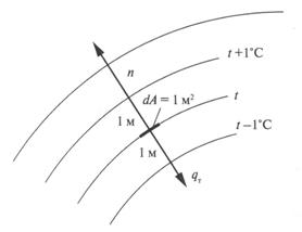
Isotherms; - ------ - heat current lines.
Change in the thermal conductivity of building materials with a change in their density is due to the fact that almost any building material consists of skeleton- the main building material and air. K.F. For example, Fokin cites the following data: the thermal conductivity of an absolutely dense substance (without pores), depending on the nature, has a thermal conductivity from 0.1 W / m o C (for plastic) to 14 W / m o C (for crystalline substances with a heat flow along the crystalline surface), while air has a thermal conductivity of about 0.026 W / m o C. The higher the density of the material (less porosity), the greater the value of its thermal conductivity. It is clear that light heat-insulating materials have a relatively low density.
Differences in porosity and thermal conductivity of the skeleton lead to differences in the thermal conductivity of materials, even at the same density. For example, the following materials (Table 1) at the same density, ρ 0 \u003d 1800 kg / m 3, have different thermal conductivity values:
Table 1.
The thermal conductivity of materials with the same density is 1800 kg/m 3 .
| Material |
Thermal conductivity, W / (m o C) |
| Cement-sand mortar | 0,93 |
| Brick | 0,76 |
| Asphalt | 0,72 |
| Portland cement stone | 0,46 |
| asbestos cement | 0,35 |
With a decrease in the density of the material, its thermal conductivity l decreases, since the influence of the conductive component of the thermal conductivity of the material skeleton decreases, but, however, the influence of the radiation component increases. Therefore, a decrease in density below a certain value leads to an increase in thermal conductivity. That is, there is a certain density value at which the thermal conductivity has a minimum value. There are estimates that at 20 ° C in pores with a diameter of 1 mm, the thermal conductivity by radiation is 0.0007 W / (m ° C), with a diameter of 2 mm - 0.0014 W / (m ° C), etc. Thus, thermal conductivity by radiation becomes significant for thermal insulation materials with low density and large pore sizes.
The thermal conductivity of a material increases with an increase in the temperature at which heat transfer occurs. An increase in the thermal conductivity of materials is explained by an increase in the kinetic energy of the molecules of the skeleton of a substance. The thermal conductivity of air in the pores of the material also increases, and the intensity of heat transfer in them by radiation. In construction practice, the dependence of thermal conductivity on temperature of great importance does not have to recalculate the thermal conductivity values of materials obtained at temperatures up to 100 ° C, to their values \u200b\u200bat 0 ° C, the empirical formula O.E. Vlasov:
λ o = λ t / (1+β . t), (2.2)
where λ o is the thermal conductivity of the material at 0 o C;
λ t - thermal conductivity of the material at t about C;
β - temperature coefficient of change in thermal conductivity, 1/ o C, for various materials, equal to about 0.0025 1/ o C;
t is the temperature of the material at which its thermal conductivity is equal to λ t .
For a flat homogeneous wall of thickness δ (Fig. 2), the heat flux transferred by thermal conductivity through a homogeneous wall can be expressed by the equation:
where τ 1 ,τ2- temperature values on the wall surfaces, o C.
It follows from expression (2.3) that the temperature distribution over the wall thickness is linear. The value δ/λ is named thermal resistance of the material layer and marked R T, m 2. about C / W:
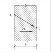
Fig.2. Temperature distribution in a flat homogeneous wall
Therefore, the heat flux q T, W / m 2, through a homogeneous plane-parallel wall with a thickness δ , m, from a material with thermal conductivity λ, W/m. about C, can be written in the form
The thermal resistance of the layer is the thermal conductivity resistance, equal to the temperature difference on opposite surfaces of the layer during the passage of a heat flux through it with a surface density of 1 W/m 2 .
Heat transfer by thermal conductivity takes place in the material layers of the building envelope.
2.1.2 Convection
Convection- transfer of heat by moving particles of matter. Convection takes place only in liquid and gaseous substances, as well as between a liquid or gaseous medium and the surface of a solid body. In this case, there is a transfer of heat and thermal conductivity. The combined effect of convection and heat conduction in the boundary region near the surface is called convective heat transfer.
Convection takes place on the outer and inner surfaces of the building fences. In the heat exchange of the internal surfaces of the room, convection plays essential role. At different temperatures of the surface and the air adjacent to it, the heat transfers to a lower temperature. The heat flux transmitted by convection depends on the mode of motion of the liquid or gas washing the surface, on the temperature, density and viscosity of the moving medium, on the surface roughness, on the difference between the temperatures of the surface and the surrounding medium.
The process of heat exchange between the surface and the gas (or liquid) proceeds differently depending on the nature of the occurrence of gas motion. Distinguish natural and forced convection. In the first case, the movement of gas occurs due to the temperature difference between the surface and the gas, in the second - due to forces external to this process (fan operation, wind).
Forced convection in the general case can be accompanied by the process of natural convection, but since the intensity of forced convection noticeably exceeds the intensity of natural convection, when considering forced convection, natural convection is often neglected.
In the future, only stationary processes of convective heat transfer will be considered, assuming that the speed and temperature are constant in time at any point in the air. But since the temperature of the elements of the room changes rather slowly, the dependences obtained for stationary conditions can be extended to the process non-stationary thermal conditions of the room, at which at each considered moment the process of convective heat transfer on the inner surfaces of the fences is considered to be stationary. The dependences obtained for stationary conditions can also be extended to the case of a sudden change in the nature of convection from natural to forced, for example, when a recirculation device for heating a room (fan coil or split system in heat pump mode) is turned on in a room. Firstly, the new air movement regime is established quickly and, secondly, the required accuracy of the engineering assessment of the heat transfer process is lower than possible inaccuracies from the lack of heat flux correction during the transition state.
For engineering practice of calculations for heating and ventilation, convective heat transfer between the surface of the building envelope or pipe and air (or liquid) is important. In practical calculations, to estimate the convective heat flux (Fig. 3), Newton's equations are used:
![]() ,
(2.6)
,
(2.6)
where q to- heat flux, W, transferred by convection from the moving medium to the surface or vice versa;
ta- temperature of the air washing the surface of the wall, o C;
τ - temperature of the wall surface, o C;
α to- coefficient of convective heat transfer on the wall surface, W / m 2. o C.
Fig.3 Convective heat exchange of the wall with air
Convection heat transfer coefficient, a to- a physical quantity numerically equal to the amount of heat transferred from air to the surface of a solid body by convective heat transfer at a difference between air temperature and body surface temperature equal to 1 o C.
With this approach, the entire complexity of the physical process of convective heat transfer lies in the heat transfer coefficient, a to. Naturally, the value of this coefficient is a function of many arguments. For practical use, very approximate values are accepted a to.
Equation (2.5) can be conveniently rewritten as:
where R to - resistance to convective heat transfer on the surface of the enclosing structure, m 2. o C / W, equal to the temperature difference on the surface of the fence and the air temperature during the passage of a heat flux with a surface density of 1 W / m 2 from the surface to the air or vice versa. Resistance R to is the reciprocal of the convective heat transfer coefficient a to:
2.1.3 Radiation
Radiation (radiant heat transfer) is the transfer of heat from the surface to the surface through a radiant medium by electromagnetic waves that transform into heat (Fig. 4).
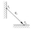
Fig.4. Radiant heat transfer between two surfaces
Any physical body that has a temperature other than absolute zero radiates energy into the surrounding space in the form of electromagnetic waves. The properties of electromagnetic radiation are characterized by the wavelength. Radiation that is perceived as thermal and has wavelengths in the range of 0.76 - 50 microns is called infrared.
For example, radiant heat exchange occurs between surfaces facing the room, between the outer surfaces of various buildings, the surfaces of the earth and sky. Radiant heat exchange between the inner surfaces of the room enclosures and the surface of the heater is important. In all these cases, the radiant medium that transmits thermal waves is air.
In the practice of calculating the heat flux in radiant heat transfer, a simplified formula is used. The intensity of heat transfer by radiation q l, W / m 2, is determined by the temperature difference of the surfaces involved in radiant heat transfer:
![]() ,
(2.9)
,
(2.9)
where τ 1 and τ 2 are the temperature values of the surfaces exchanging radiant heat, o C;
α l - coefficient of radiant heat transfer on the wall surface, W / m 2. o C.
Heat transfer coefficient by radiation, a l- a physical quantity numerically equal to the amount of heat transferred from one surface to another by radiation at a difference between the surface temperatures equal to 1 o C.
We introduce the concept resistance to radiant heat transfer R l on the surface of the building envelope, m 2. o C / W, equal to the temperature difference on the surfaces of the fences exchanging radiant heat, when passing from the surface to the surface of a heat flux with a surface density of 1 W / m 2.
Then equation (2.8) can be rewritten as:
Resistance R l is the reciprocal of the radiant heat transfer coefficient a l:
2.1.4 Thermal resistance of the air gap
For uniformity, heat transfer resistance closed air gaps located between the layers of the building envelope, called thermal resistance R in. p, m 2. about C / W.
The scheme of heat transfer through the air gap is shown in Fig.5.
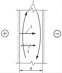
Fig.5. Heat transfer in the air gap
Heat flux passing through the air gap q c. P, W / m 2, consists of flows transmitted by thermal conductivity (2) q t, W/m 2 , convection (1) q to, W/m 2 , and radiation (3) q l, W/m 2 .
q c. n =q t +q to +q l . (2.12)
In this case, the share of the flux transmitted by radiation is the largest. Let us consider a closed vertical air layer, on the surfaces of which the temperature difference is 5 ° C. With an increase in the thickness of the layer from 10 mm to 200 mm, the proportion of heat flow due to radiation increases from 60% to 80%. In this case, the share of heat transferred by thermal conductivity drops from 38% to 2%, and the share of convective heat flow increases from 2% to 20%.
The direct calculation of these components is rather cumbersome. Therefore, in normative documents data are given on the thermal resistance of closed air spaces, which in the 50s of the twentieth century was compiled by K.F. Fokin based on the results of experiments by M.A. Mikheev. If there is a heat-reflecting aluminum foil on one or both surfaces of the air gap, which hinders radiant heat exchange between the surfaces framing the air gap, the thermal resistance should be doubled. To increase the thermal resistance of closed air gaps, it is recommended to bear in mind the following conclusions from the studies:
1) thermally efficient are interlayers of small thickness;
2) it is more rational to make several layers of small thickness in the fence than one large one;
3) it is desirable to place air gaps closer to the outer surface of the fence, since in this case winter time the heat flux by radiation decreases;
4) vertical layers in the outer walls must be blocked by horizontal diaphragms at the level of interfloor ceilings;
5) to reduce the heat flux transmitted by radiation, one of the interlayer surfaces can be covered with aluminum foil having an emissivity of about ε=0.05. Covering both surfaces of the air gap with foil does not significantly reduce heat transfer compared to covering one surface.
Questions for self-control
1. What is the heat transfer potential?
2. List the elementary types of heat transfer.
3. What is heat transfer?
4. What is thermal conductivity?
5. What is the thermal conductivity of the material?
6. Write the formula for the heat flux transferred by thermal conductivity in a multilayer wall at known temperatures of the inner t in and outer t n surfaces.
7. What is thermal resistance?
8. What is convection?
9. Write the formula for the heat flux transferred by convection from air to the surface.
10. Physical meaning of the coefficient of convective heat transfer.
11. What is radiation?
12. Write the formula for the heat flux transmitted by radiation from one surface to another.
13. Physical meaning of the radiant heat transfer coefficient.
14. What is the name of the resistance to heat transfer of a closed air gap in the building envelope?
15. Of what nature does the total heat flow through the air gap consist of heat flows?
16. What nature of the heat flow prevails in the heat flow through the air gap?
17. How does the thickness of the air gap affect the distribution of flows in it.
18. How to reduce the heat flow through the air gap?
2.1.5 Heat transfer coefficients on the inner and outer surfaces
Consider a wall separating a room with a temperature t in from the external environment with a temperature t n. The outer surface by convection exchanges heat with the outside air, and radiant - with the surrounding surfaces, having a temperature t env. n. The same is true from the inside. It can be written that the heat flux with density q, W / m 2, passing through the wall, is equal to
where t env. in and t env. n is the temperature of the surfaces surrounding the inner and outer planes of the wall under consideration, respectively, o C;
α k. in, α k. n - coefficients of convective heat transfer on the inner and outer surfaces of the wall, m 2. o C / W;
α l. c, α l. n - coefficients of radiant heat transfer on the inner and outer surfaces of the wall, m 2. o C / W.
In engineering calculations, it is accepted that heat transfer on the surfaces of enclosing structures is not divided into radiant and convective components. It is believed that heat absorption occurs on the inner surface of the outer fence in a heated room, estimated by the total coefficient α in, W / (m 2. o C), and on the outer surface - heat transfer, the intensity of which is determined by the heat transfer coefficient α n, W / (m 2 o C). In addition, it is generally accepted that the temperature of the air and the surrounding surfaces are equal to each other, that is t env. in \u003d t in, and t env. n \u003d t n. That is
Therefore, it is accepted that heat transfer coefficients on the outer and inner surfaces fences are equal to the sum of the coefficients of radiant and convective heat transfer on each side:
The heat transfer coefficient on the outer or inner surface, in physical terms, is the heat flux density given off by the corresponding surface to its environment (or vice versa) with a temperature difference of the surface and the environment of 1 o C. The reciprocals of the heat transfer coefficients are commonly called resistance to heat transfer on the internalR in, m 2. about C / W, and outdoorR n, m 2. o C / W, fencing surfaces:
R in \u003d 1 /α in;R n \u003d 1 /α n. ( 2.16)
2.1.6 Heat transfer through a sandwich wall
If on one side of a multilayer wall consisting of n layers, the temperature is maintained t in, and on the other hand t n t in, then there is a heat flux q, W/m 2 (Fig.6).
This heat flow moves from a medium with a temperature t in, o C, to a medium with a temperature t n, o C, passing sequentially from the internal environment to the inner surface with a temperature τ in, o C:
q= (1/R c). (t in - τ in), (2.17)
then from the inner surface through the first layer with thermal resistance R T,1 to the junction of the first and second layers:
q= (1/R T,1). (τ in -t1) , (2.18)
after that through all other layers
q= (1/R T, i). (t i -1 -t i) , (2.19)
and finally from the outer surface with temperature τ n to the outdoor environment with temperature t n:
q= (1/R n). (τ n -t n) , (2.20)
where R T,i- thermal resistance of the layer with number i, m 2. about C / W;
R in,R n- resistance to heat transfer on the inner and outer surfaces, m 2. o C / W;
t i -1 - temperature, o C, at the junction of layers with numbers i-1 and i;
t i- temperature, o C, at the junction of layers with numbers i and i+1.
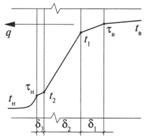
Fig.6. Temperature distribution during heat transfer through a multilayer wall
Rewriting (2.16) - (2.19) with respect to the temperature differences and summing them up, we get the equality:
t in- t n= q. (R in+R T ,1 +R T ,2 +…+R T, i+…. + R T,n+R n) ( 2.21)
The expression in parentheses - the sum of the thermal resistances of plane-parallel layers of the fence located in series along the course of the heat flow and the resistance to heat transfer on its surfaces is called total heat transfer resistance of the fence R o, m 2. about C / W:
R o \u003d R in+ΣR T, i+R n, (2.22)
and the sum of the thermal resistances of the individual layers of the fence - its thermal resistance R T, m 2. about C / W:
R T =R T,1 +R Т,2 +…+R in. p +…. +R T,n, (2.23)
where R T,1 ,R Т,2 ,…,R T,n- thermal resistances of individual plane-parallel layers of layers of the enclosing structure located in series along the course of the heat flow, m 2. o C / W, determined by the formula (2.4);
R in. P- thermal resistance of a closed air gap, m 2. o C / W, according to clause 2.1.4
According to the physical meaning, the total resistance to heat transfer of the fence R o- this is the temperature difference between the media on different sides of the fence, which forms a heat flux passing through it with a density of 1 W / m 2, while thermal resistance of sandwich construction- the temperature difference between the outer and inner surfaces of the fence, which forms the heat flux passing through it with a density of 1 W / m 2, From (2.22) it follows that the heat flux q, W / m 2 passing through the fence is proportional to the temperature difference of the media on different sides of the fence ( t in -t n) and inversely proportional to the total resistance to heat transfer R o
q= (1/R o). (t in -t n), (2.24)
2.1.7 Reduced resistance to heat transfer
When deriving the total resistance to heat transfer, a plane-parallel fence was considered. And the surfaces of most modern enclosing structures are not isothermal, that is, the temperature in different parts of the outer and inner surfaces of the structure is not the same due to the presence of various heat-conducting inclusions present in the structure /
Therefore, the concept reduced resistance to heat transfer of the enclosing structure, which is the resistance to heat transfer of a single-layer enclosing structure of the same area, through which the same heat flow with the real structure passes with the same difference between the temperature of the indoor and outdoor air. It is important to note that the given heat transfer resistance refers to the entire structure or its section, and not to an area of 1 m 2. This is because heat-conducting inclusions can be caused not only by regularly laid connections, but also by rather large elements of fastening facades to columns, and by the columns themselves, cutting into the wall, and adjoining one fence to another.
Therefore, the reduced resistance to heat transfer of a structure (or a section of a structure) can be determined by the expression:
where Q- the heat flux passing through the structure (or section of the structure), W;
A- area of the structure (or section of the structure), m 2.
The expression is, in its meaning, the area-averaged (or reduced to unit area) density of the heat flux through the structure, that is, it can be written:
From (2.24) and (2.25) it follows:
Enclosing structures using effective heat-insulating materials are made in such a way that the layer thermal insulation material covers, as far as possible, a large area of \u200b\u200bthe structure. The cross sections of heat-conducting inclusions are made as small as possible. Therefore, it is possible to single out a section of the structure remote from heat-conducting inclusions. If we neglect the influence of heat-conducting inclusions in this area, then its heat-shielding properties can be characterized using conditional resistance to heat transfer defined by formula (2.22). The ratio of the value of the reduced heat transfer resistance of the structure to the value of the conditional heat transfer resistance of the considered section is called thermal uniformity coefficient:
The value of the coefficient of heat engineering uniformity evaluates how fully the possibilities of the heat-insulating material are used, or in other words, what is the effect of heat-conducting inclusions.
This coefficient is almost always less than unity.
Its equality to unity means that there are no heat-conducting inclusions, and the possibilities of using a layer of heat-insulating material are used to the maximum. But such structures practically do not exist.
The coefficient of thermal engineering homogeneity is determined by direct calculation of the multidimensional temperature field of the structure or, in a simplified way, by , and for the case of rod connections by .
The reciprocal of the reduced resistance to heat transfer is called heat transfer coefficient of the enclosing structure K, W / m 2. about C:
Heat transfer coefficient of the fence To is equal to the density of the heat flux passing through the fence, with a temperature difference of media on opposite sides of it of 1 o C. Therefore, the heat flux q, W / m 2 passing through the fence due to heat transfer, can be found by the formula:
q= K. (t in -t n) . ( 2.30)
2.1.8 Temperature distribution over the section of the fence
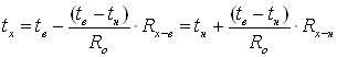
An important practical task is to calculate the temperature distribution over the section of the fence (Fig. 7). It follows from the differential equation (2.1) that it is linear with respect to the resistance to heat transfer, so we can write the temperature t x in any section of the fence:
 , (2.31)
where R x-in and R x-n- resistance to heat transfer, respectively, from internal air to point x and from outside air to point x, m 2. o C / W.
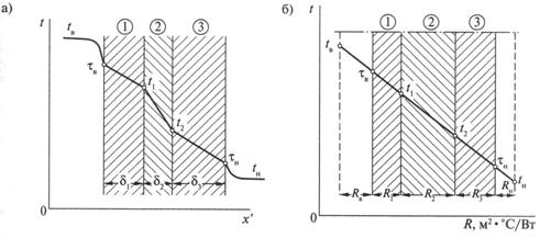
Fig.7. temperature distribution in a multilayer wall. a) on the scale of layer thicknesses, b) on the scale of thermal resistances
However, expression (2.30) refers to the enclosure without perturbing the one-dimensionality of the heat flow. For a real fence, characterized by the reduced resistance to heat transfer, when calculating the temperature distribution over the cross section of the fence, it is necessary to take into account the decrease in heat transfer resistance R x-in and R x-n using the heat engineering uniformity coefficient:
Questions for self-control
1. What is (physical meaning) the heat transfer coefficient on the surface?
2. What makes up the heat transfer coefficient on the outer surface of the fence?
3. What makes up the heat transfer coefficient on the inner surface of the fence?
4. What makes up the thermal resistance of a multilayer building envelope with plane-parallel layers along the heat flow.
5. What makes up the total resistance to heat transfer of a multilayer building envelope with plane-parallel layers along the heat flow. Write the formula for the total resistance to heat transfer.
6. The physical meaning of the thermal resistance of a multilayer building envelope with plane-parallel layers along the heat flow.
7. The physical meaning of the total heat transfer resistance of a multilayer building envelope with plane-parallel layers along the heat flow.
8. The physical meaning of the reduced resistance to heat transfer of the enclosing structure.
9. What is the conditional resistance to heat transfer of the building envelope.
10. What is the coefficient of thermal uniformity of the building envelope.
11. What is the heat transfer coefficient of the building envelope?
12. Write the formula for the heat flux transferred due to heat transfer from the internal environment with a temperature t in to the external environment with a temperature t n through a multilayer wall.
13. Draw a qualitative picture of the temperature distribution in a two-layer wall at known ambient temperatures t in and t n, if λ 1 >λ 2.
14. Draw a qualitative picture of the temperature distribution in a two-layer wall at known ambient temperatures t in and t n, if λ 1
15. Write a formula for determining the temperature of the inner surface of a two-layer wall in at known temperatures of the media t in and t n, layer thicknesses δ 1 and δ 2, thermal conductivity coefficients λ 1 and λ 2.
16. Write a formula for determining the temperature of the outer surface of a two-layer wall τ n in at known temperatures of the media t in and t n, layer thicknesses δ 1 and δ 2, thermal conductivity coefficients λ 1 and λ 2.
17. Write a formula for determining the temperature between the layers of a two-layer wall t at known media temperatures t in and t n, layer thicknesses δ 1 and δ 2, thermal conductivity coefficients λ 1 and λ 2.
18. Write a formula for determining the temperature t x in any section of a multilayer wall at known temperatures of the media t in and t n, layer thicknesses, thermal conductivity coefficients.
2.2 Humidity regime of enclosing structures
The humidity regime of fences is closely related to their thermal regime, therefore it is studied in the course of building thermal physics. Humidification of building materials in fences adversely affects the hygienic and operational performance of buildings.
2.2.1 Causes of moisture in fences
The ways of moisture getting into fences are different, and measures to reduce the moisture content of building materials in them depend on the cause of moisture. These reasons are as follows.
Construction (initial) moisture, that is, the moisture remaining in the fence after the construction of the building. A number of construction processes are "wet", for example, concreting, laying of bricks and piece blocks: cellular concrete, expanded clay concrete and others, plastering. To reduce the duration of wet construction processes in winter conditions, dry processes are used. For example, tongue-and-groove gypsum hydrophobized panels are placed in the inner layers of the outer walls of a floor-by-floor section. Plain internal plaster replaced with drywall sheets.
Construction moisture must be removed from the fences in the first 2 - 3 years of operation of the building. Therefore, it is very important that the heating and ventilation systems work well in it, which will bear the additional load associated with the evaporation of water.
ground moisture, the moisture that can penetrate the fence from the ground by capillary suction. To prevent ground moisture from entering the fence, builders install waterproofing and vapor barrier layers. If the waterproofing layer is damaged, ground moisture can rise through the capillaries in the building materials of the walls to a height of 2 - 2.5 m above the ground.
atmospheric moisture, which can penetrate the fence during oblique rain, when roofs leak in the area of \u200b\u200bthe cornices, and when external drains malfunction. The strongest impact of rain moisture is observed at full cloudiness with prolonged drizzling rain with wind, with high humidity of the outside air. To prevent moisture from entering the wall from the wetted outer surface, special textured layers are used that poorly pass the liquid phase of moisture. Attention is drawn to the sealing of joints wall panels in large-panel housing construction, for sealing the perimeters of windows and other openings.
Operational moisture gets into the fence from internal sources: during production processes associated with the use or release of water, during wet cleaning of premises, during breaks in water supply and sewer networks. With regular use of water indoors, waterproof floors and walls are made. In case of accidents, it is necessary to remove moisture from the building envelope as soon as possible.
Hygroscopic moisture located inside the enclosure due to the hygroscopicity of its materials. Hygroscopicity is the property of a material to absorb (sorb) moisture from the air. With a long stay of a building product in air with constant temperature and relative humidity, the amount of moisture contained in the material becomes unchanged (equilibrium). This balance of moisture content corresponds to the hygrothermal state of the external air-humid environment and, depending on the properties of the material ( chemical composition, porosity, etc.) can be larger or smaller. It is undesirable to use materials with high hygroscopicity in fences. At the same time, the use of hygroscopic plasters (lime) is practiced in places where people periodically stay, for example, in churches. Walls that absorb moisture when the air is humidified and release it when the air humidity decreases are said to "breathe".
vaporous moisture, located in the air, filling the pores of building materials. Under adverse conditions, moisture can condense inside the fences. To avoid negative consequences moisture condensation inside the fence, it must be properly designed to reduce the risk of condensation and create conditions for the complete drying of moisture condensed during the winter in summer.
condensed moisture on the inner surfaces of the fences at high humidity of the indoor air and the temperature of the inner surface of the fence is below the dew point. Measures to combat the dampening of the inner surface of the fences are associated with ventilation of the premises, which reduces the humidity of the indoor air, and with the insulation of the building envelope, which excludes a decrease in temperature, both on the smooth surface of the fence and in places of heat-conducting inclusions.
2.2.2 Negative effects of wetting outdoor enclosures
It is known that with an increase in the moisture content of materials, the thermal qualities fencing by increasing the coefficient of thermal conductivity of materials, which leads to an increase in the heat loss of the building and high energy consumption for heating.
Thermal conductivity increases with increasing moisture content of the material due to the fact that the water in the pores of the material has a thermal conductivity coefficient of about 0.58 W / m o C, which is 22 times higher than that of air. The high intensity of the increase in the thermal conductivity of the material at low humidity is due to the fact that when the material is moistened, small pores and capillaries are first filled with water, the effect of which on the thermal conductivity of the material is greater than the effect of large pores. The coefficient of thermal conductivity increases even more sharply if the wet material freezes, since ice has a thermal conductivity of 2.3 W / m o C, which is 80 times greater than that of air. It is impossible to establish a general mathematical dependence of the thermal conductivity of a material on its moisture content for all building materials, since it is greatly influenced by the shape and location of the pores. Humidification of building structures leads to a decrease in their heat-shielding qualities, leading to an increase in the coefficient of thermal conductivity of the wet material.
On the inner surfaces of the enclosure with wet layers, a lower temperature is formed than with dry layers, which creates an unfavorable radiation environment in the room. If the temperature on the surface of the fence is below the dew point, then condensation may form on this surface. Wet building material is unacceptable, as it is a favorable environment for the development of fungi, mold and other microorganisms in it, spores and tiny particles of which cause allergies and other diseases in people. Thus, the dampening of building structures worsens hygienic qualities fences.
The greater the moisture content of the material, the less frost-resistant the material, and, therefore, short-lived. Freezing in the pores of materials and at the junctions of layers, water breaks these pores, since water expands when it turns into ice. Deformation also occurs in fences subject to moisture, but made of non-moisture resistant materials such as plywood, gypsum. Therefore, the use of non-moisture resistant materials in outdoor enclosures is limited. Therefore, wetting building materials can have negative effects on technical qualities fences.
2.2.3 Relationship of moisture to building materials
By the nature of its interaction with water solid bodies are divided into wetted (hydrophilic) and non-wettable (hydrophobic). Hydrophilic building materials include concrete, gypsum, and water-based binders. To hydrophobic - bitumen, resins, mineral wool on non-wettable binders. Hydrophilic materials actively interact with water, while partially wettable and non-wettable materials interact less actively.
The factor significantly affecting the nature of the interaction of the material with moisture in the air, or in direct contact with water is capillary-porous structure most building materials. When interacting with moisture, the physical, mechanical and thermal properties of building materials can change.
For a correct understanding of the ways of movement of moisture in building envelopes and methods for preventing adverse processes or their consequences, it is necessary to know the forms of communication between moisture and building materials.
A substantiated system of energy classification of the relationship between moisture and material was developed by Academician P.A. Rebinder. According to the nature of the energy of binding moisture to the substance and the magnitude of the energy level, three types of this connection are distinguished.
Chemical form of bond moisture with the material is the most durable, because moisture in this case is necessary for chemical reactions. Such moisture is part of the structural lattice of materials such as crystalline hydrates and does not participate in moisture exchange processes. Therefore, when considering the processes of moisture transfer through the fence, it can be ignored.
Physico-chemical bond moisture with building materials is manifested in adsorption on the inner surface of the pores and capillaries of the material. The adsorbed moisture is subdivided into the moisture of the primary monomolecular layers, which is characterized by a high energy level of bonding with the surface of hydrophilic materials, and the moisture of the subsequent polymolecular layers that make up the water film held by capillary forces. To remove monomolecular and partially polymolecular moisture, natural drying forces in conventional natural conditions and room conditions. The physicochemical form of bonding also includes osmotically (structurally) bound moisture in plant cells of organic materials of plant origin. This moisture can be removed by natural drying.
Physical-mechanical connection determines the retention of moisture in pores and capillaries by the forces of capillary pressure and wetting of hydrophilic materials. This moisture moves inside the material when pressures exceed capillary pressure and evaporates from the surface layers of structures during natural drying. The bond between water and microcapillaries has the highest physical and mechanical strength.
2.2.4 Humid air
Atmospheric air is composed of oxygen, nitrogen, carbon dioxide and a small amount of inert gases always contains some moisture in the form of water vapor. A mixture of dry air and water vapor is called humid air.
With sufficient accuracy for technical calculations, we can assume that wet air obeys all the laws of an ideal gas mixture. Each gas, including steam, which is part of the mixture, occupies the same volume as the entire mixture.
The steam is under its partial pressure, which is determined by the Mendeleev-Klaiperon equation:
where M i- mass of the i-th gas, in this case water vapor, kg;
R- universal gas constant, equal to 8 314.41 J / (kmol. K);
T- mixture temperature in absolute scale, K;
V- the volume occupied by a mixture of gases, m 3;
μ i- molecular weight of gas, kg/mol. For water vapor μ p \u003d 18.01528 kg / kmol.
According to Dalton's law, the sum of the partial pressures of the gas components of the mixture is full mixture pressure. Moist air is considered to be binary mixture, consisting of water vapor and dry part atmospheric air , whose effective molecular weight is μ in ≈ 29 kg/mol. barometric pressure of moist air P b, Pa, is the sum of the partial pressure of dry air e st, Pa, and the partial pressure of steam e p, Pa:
The partial pressure of water vapor is also called water vapor pressure.
To characterize the measure of air humidification, the concept is used relative humidityφ in, which shows the degree of air saturation with water vapor in% or fractions of a unit of full saturation at the same temperature and pressure.
At a relative humidity of 100%, the air is completely saturated with water vapor and is called rich. The partial pressure of saturated water vapor is also called saturation pressure air, water vapor or maximum water vapor pressure and denote E. The value of relative humidity φ in is equal to the ratio of the partial pressure of water vapor e p in moist air at certain atmospheric pressure and temperature to saturation pressure E under the same conditions:
or φ,% . (2.36)
The partial pressure of saturated water vapor - the maximum elasticity of water vapor - at a given barometric pressure is a function of temperature t only:
Its values are determined experimentally and are given in special tables. In addition, there are a number of formulas approximating the dependence of E on temperature. For example, the formulas given in:
above the ice surface at a temperature of - 60 o C to 0 o C
 , (2.38)
above the surface of pure water at a temperature of 0 ° C to 83 ° C
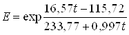 , (2.39)
Hygienists consider the range of relative humidity from 30% to 60% normal for a person to stay. When the relative humidity is above 60%, the evaporation of moisture from the human skin is difficult and his health deteriorates. At lower relative humidity than 30%, evaporation from the surface of the skin and mucous membranes of a person increases, which causes dry skin, sore throat, contributing to colds.
With an increase in air temperature of a given absolute humidity, its relative humidity decreases, since, in accordance with formula (2.36), the value of the partial pressure of water vapor will remain unchanged, and the saturation pressure will increase due to an increase in temperature. On the contrary, when the air is cooled, the relative humidity will increase due to a decrease in the saturation pressure E. As the air cools at a certain temperature, when e p becomes equal to E, the relative humidity of the air will become equal to 100%, that is, the air will reach full saturation with water vapor. The temperature t p, o C, at which air with a certain absolute humidity is in a state of complete saturation, is called dew point. If the air is cooled below the dew point, then some of the moisture will begin to condense out of the air. In this case, the air will remain saturated with water vapor, and the air saturation pressure E will decrease according to the temperature reached. Moreover, the air temperature at each moment of time will be the dew point for the formed absolute air humidity.
When moist air comes into contact with the inner surface of the outer enclosure, which has a temperature τ in below the air dew point t p, water vapor will condense on this surface. Thus, the conditions for the absence of condensation on the inner surface of the fence and in its thickness is to maintain the temperature above the dew point, which means that the partial pressure of water vapor at each point in the section of the fence should be less than the saturation pressure.
2.2.5 Material moisture
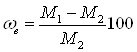
In capillary-porous materials in a natural air environment, there is always a certain amount of chemically unbound moisture. If a sample of natural material is dried, its mass will decrease. Weight moisture materialω in,%, is determined by the ratio of the mass of moisture contained in the sample to the mass of the sample in a dry state:
 , (2.40)
where M 1- weight of the wet sample, kg,
M 2- mass of dry sample, kg.
Bulk moistureω about,%, is determined by the ratio of the volume of moisture contained in the sample to the volume of the sample:
where V 1- the volume of moisture in the sample, m 3, V 2- the volume of the sample itself, m 3 .
There is a relationship between the weight ω in and the volumetric moisture content ω about the material:
![]() , (2.42)
, (2.42)
where ρ - the density of the material in a dry state, kg / m 3.
Humidity is often used in calculations.
2.2.6 Sorption and desorption
With a long stay of a material sample in moist air with constant temperature and relative humidity, the mass of moisture contained in the sample will become unchanged - equilibrium. With an increase in the relative humidity of the air, the mass of moisture in the material increases, and with an increase in temperature, it decreases. This is the equilibrium moisture content of the material, corresponding to the thermal and moisture state of the air environment, depending on the chemical composition, porosity and some other properties of the material, it can be more or less. The process of moistening dry material placed in a humid air environment is called sorption, and the process of reducing the moisture content of excessively moist material in a humid air environment - desorption.
The pattern of change in the equilibrium moisture content of the material in an air environment with a constant temperature and increasing relative humidity is expressed by the sorption isotherm.
For the vast majority of building materials, the sorption and desorption isotherms do not coincide. The difference in weight moisture content of a building material at the same relative air humidity φ is called sorption hysteresis. Figure 8 shows the isotherms of sorption and desorption of water vapor for foam silicate. on . It can be seen from Fig. 8 that, for example, for φ = 40% during sorption, silicate foam has a weight moisture content ω в = 1.75%, and during desorption ω в = 4%, therefore, the sorption hysteresis is 4-1.75 = 3 .25%.
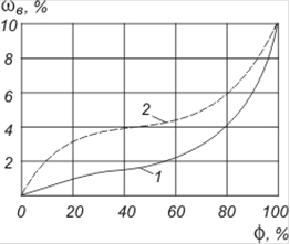
Fig.8. Weight moisture content of foam silicate during sorption (1) and desorption (2)
The values of sorption moisture content of building materials are given in various literary sources, for example, in.
2.2.7 Vapor permeability of fences
The exclusion of water vapor condensation on the inner surface of the fence cannot guarantee the absence of moisture condensation in the thickness of the fence.
Moisture in a building material can be in three different phases: solid, liquid and vapor. Each phase spreads according to its own law. In the climatic conditions of Russia, the most urgent problem is the movement of water vapor in the winter. It is known from experimental studies that steam transfer potential- its driving force is the partial pressure of water vapor in the air e, Pa. Inside the building materials of the fence, moist air is in the pores of the material. Steam moves from a higher partial pressure to a lower one.
During the cold season, the indoor air temperature is much higher than outside. Higher temperature corresponds to more high pressure saturation with water vapor E. Despite the fact that the relative humidity of the indoor air is less than the relative humidity of the outdoor air, the partial pressure of water vapor in the indoor air e in significantly exceeds the partial pressure of water vapor in the outside air e n. Therefore, the flow of steam is directed from the room to the outside. The process of penetration of steam through the fence refers to diffusion processes. In other words, water vapor diffuses through the fence. Diffusion is a purely molecular phenomenon, which is the replacement of molecules of one gas by molecules of another, in this case, the replacement of dry air molecules in the pores of building materials by water vapor molecules. And the process of diffusion of water vapor through the fences is called vapor permeability.
To avoid confusion in terminology, we will immediately stipulate that vapor permeability- this is a property of materials and a structure made of them to pass water vapor through itself, and vapor permeability is the process of steam penetrating through a material or enclosure.
Vapor permeability μ depends on physical properties material and reflects its ability to pass water vapor diffusing through itself. The vapor permeability of the material μ is quantitatively equal to the diffusion flow of water vapor, mg/h, passing through m 2 of the area perpendicular to the flow, with a water vapor partial pressure gradient along the flow equal to 1 Pa/m.
The calculated values of μ are given in the reference tables. Moreover, for isotropic materials, μ does not depend on the direction of the moisture flow, and for anisotropic (wood, other materials with a fibrous structure or pressed) the values of μ are given depending on the ratio of the directions of the flow of steam and fibers.
The vapor permeability for heat-insulating materials, as a rule, loose and open-pore, has large values, for example, for mineral wool boards on a synthetic binder at a density of ρ = 50 kg / m 3, the vapor permeability coefficient is equal to μ = 0.60 mg / (hour m. Pa ). Materials of greater density correspond to a lower vapor permeability coefficient, for example, heavy concrete on dense aggregates has μ = 0.03 mg / (h.m. Pa). However, there are exceptions. Extruded polystyrene foam, a closed-cell insulation, with a density of ρ = 25 - 45 kg / m 3 has μ = 0.003 - 0.018 mg / (h.m. Pa) and practically does not pass steam through itself.
Materials with minimal vapor permeability are used as vapor barrier layers. For sheet materials and thin layers vapor barrier due to the very small value of μ, the reference tables give the vapor permeation resistances and the thicknesses of these layers.
The vapor permeability of air is equal to μ=0.0062 m2. h. Pa/mg in the absence of convection and μ=0.01 m2. h. Pa/mg during convection. Therefore, when calculating the resistance to vapor permeability, it should be borne in mind that the vapor barrier layers of the fence that do not provide continuity (having gaps) (vapor barrier film broken by the internal bonds of the fence, sheet vapor barrier layers, even overlapped, but without smearing the joints with vapor barrier mastic), will have a greater vapor permeability than without taking into account this circumstance.
It is known from physics that there is a complete analogy between vapor permeation and heat conduction processes. Moreover, it is observed analogue in the processes of heat transfer and moisture transfer on the surfaces of the fence. Therefore, one can consider analogy between the complex processes of heat transfer and moisture transfer through the fence. Table 2 presents direct analogues in these processes.
table 2
Analogy between heat transfer and moisture transfer processes during vapor diffusion
| thermal field | Humidity field |
|
Temperature indoor air t in, o C; inner surface τ in, o C; at the junctions of the layers t i, o C; outer surface τ n, o C; outside air t n, about S. |
Partial pressure of water vapor: in the inner air e in, Pa; on the inner surface e VP, Pa; at the junctions of the layers ei, Pa; outer surface e np, Pa; in the outside air e n, Pa. |
|
Thermal conductivity of the material λ , W / (m. o C) |
Vapor permeability of the material μ, mg/ (h.m. Pa) |
|
Thermal resistance layer thickness δ, m, R T=δ/ λ , m 2. about C / W |
Vapor resistance layer thick δ , m, R p \u003d δ / μ, m 2. h. Pa / mg (2.43) |
|
Heat transfer coefficients on the inner surface α in, W / (m 2. o C); on the outer surface α n, W / (m 2. o C). |
Moisture return coefficients on the inner surface β in, mg / (hours m 2. Pa); on the outer surface β n, mg / (hours m 2. Pa). |
|
Resistance to heat transfer on the surfaces of the fence on the inside R in \u003d 1 / α in, m 2. o C / W; on the outside R n \u003d 1 / α n, m 2. o C / W; |
Resistance to moisture release on the surfaces of the fence on the inner R p. in \u003d 1 / β in, m 2. h. Pa / mg; (2.44) on the outer R p. n \u003d 1 / β n, m 2. h. Pa / mg. (2.45) |
|
Total heat transfer resistance of the fence R o \u003d R in + Σδ / λ + R n, m 2. o C / W |
Overall resistance to vapor permeation of the fence R about. p \u003d R p. in + Σδ / λ + R p. n, m 2. h. Pa / mg (2.46) |
|
Heat flux density through the fence q \u003d (t in -t n) / R o, W / m 2 |
Density of the diffusion flux of moisture through the fence g \u003d (e in -e n) / R o. p, mg / (h. m 2) (2.47) |
According to its physical meaning vapor permeability layer fences - this is the difference in the elasticity of water vapor, which must be created on the surfaces of the layer so that a vapor flow of 1 mg / h diffuses through 1 m 2 of its area.
The total resistance to vapor permeability of the enclosing structure(during vapor diffusion) is the sum of the resistance to vapor permeability of all its layers and the resistance to moisture exchange on its surfaces, as follows from expression (2.43).
The moisture transfer coefficient, as a rule, is not used in engineering calculations of the total resistance to vapor permeability, in the calculations they use directly the resistance to moisture transfer on surfaces, assuming their values \u200b\u200bare equal to R p. in = 0.0267 m 2. h. Pa / mg, R p. n, \u003d 0.0052 m 2. h. Pa / mg.
The elasticity of water vapor diffusing through the fence, as it passes through its thickness, will change between the values \u200b\u200bof e and e n. To find the partial pressure of water vapor e x in any section of the fence (Fig. 9), use a formula similar to formula (2.30) to determine the temperature distribution over the section of the fence:
where R p. in-x, R p. n-x- resistance to vapor permeability, from the point x to the internal and external air, respectively, m 2. h. Pa / mg.
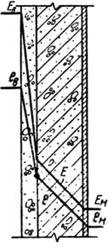
Fig.9. Distribution of partial pressure and saturation pressure of water vapor over the section of the fence
Questions for self-control.
1. Causes of moisture loss on the surface or in the thickness of the fence.
2. Negative consequences of moisture loss on the surface or in the thickness of the fence.
3. What is the difference between hydrophilic building materials and hydrophobic?
4. What is the structure of most building materials?
5. What are the three types of moisture bonding with a building material by the nature of the binding energy and the magnitude of the energy level do you know?
6. What is humid air?
7. What is the partial pressure of water vapor in moist air?
8. What makes up the barometric pressure of moist air?
9. What is relative humidity?
10. What kind of air is called saturated water vapor?
11. What temperature is called the dew point?
12. What are the conditions for the absence of condensate at any point in the section of the building envelope?
13. How is the weight moisture content of a material determined?
14. How is the volumetric moisture content of a material determined?
15. What is the equilibrium moisture content of a material?
16. What is sorption and desorption? *
17. What is the manifestation of sorption hysteresis?
18. What is the potential for water vapor transfer in building envelopes?
19. What is the diffusion of vapor through the fence?
20. What is vapor permeability?
21. What is vapor permeability?
22. What is quantitatively equal to the vapor permeability of the material μ?
23. What is a vapor barrier?
24. Physical meaning of resistance to vapor permeability of a layer?
25. What is the total resistance to vapor permeability of the building envelope?
26. Write the formula for the total resistance to vapor permeability of the fence.
27. How to determine the partial pressure of water vapor in the air at a known temperature t in and relative humidity φ in?
28. What determines the pressure of saturated water vapor?
29. Draw a qualitative picture of the distribution of the partial pressure of water vapor in a two-layer wall at known pressures in the environment e in and e n, if μ 1 > μ 2.
30. Draw a qualitative picture of the distribution of the partial pressure of water vapor in a two-layer wall at known pressures in the environment e in and e n, if μ 1
31. Write a formula for determining the partial pressure of water vapor on the inner surface of a two-layer wall e ext. pov at known pressures in media e in and e n, layer thicknesses δ 1 and δ 2, vapor permeability μ 1 and μ 2.
32. Write a formula for determining the partial pressure of water vapor on the outer surface of a two-layer wall e n. pov at known pressures in media e in and e n, layer thicknesses δ 1 and δ 2, vapor permeability μ 1 and μ 2.
33. Write a formula for determining the partial pressure of water vapor between the layers of a two-layer wall e at known pressures in media e in and e n, layer thicknesses δ 1 and δ 2, vapor permeability μ 1 and μ 2.
34. Write a formula for determining the partial pressure of water vapor e x in any section of a multilayer wall at known pressures in media e in and e n, layer thicknesses δ i , vapor permeability μ i .
2.3 Air permeability of external enclosures
2.3.1 Fundamentals
breathability called the property of building materials and enclosing structures to let air flow through them, breathability also consider the air consumption in kg, which passes through 1m 2 of the fence per hour G, kg / (m 2. h).
breathability Through fences, the process of air penetration through their leaks is called. The penetration of air from outside to inside is called infiltration, and from the room to the outside - exfiltration.
There are two types of leaks through which air filtration: pores of building materials and through slots. The gaps form the joints of wall panels, gaps in the window frames and in the places where the window adjoins the window frame, etc. Except through transverse filtration, at which the air passes through the fence through in the direction. perpendicular to the surface of the fence, exists, according to the terminology of R.E. Briling, two more types of filtration - longitudinal and internal.
Generally speaking, all outdoor enclosures have air permeability, but only infiltration through windows, balcony doors and stained-glass windows is usually taken into account in the calculation of heat loss. The density norms of the remaining fences exclude the possibility of through air permeability, which significantly affects the heat balance of the room.
As already mentioned in Chapter 2, a dense layer is made from the inside to vapor barrier the enclosing structures. This layer is usually sufficiently airtight for transverse filtration. However, if the facade layer is not dense on the outside, longitudinal filtration can occur, which means that, under the influence of wind, cold outside air passes into the building envelope and exits it elsewhere. This causes additional heat loss.
In modern exterior walls with a ventilated facade in layers of mineral wool, polystyrene foam or other foamed materials, longitudinal filtration can be observed, which locally reduces the reduced resistance of these structures due to the removal of heat by the filtered air to the atmosphere.
Even if good protection against air penetration is provided on both sides of the enclosing structure, and the inner layers are made of breathable materials, air movement inside the structure may occur due to the temperature difference in the thickness of the fence, similar to the movement of air in closed air spaces. However, internal filtration generally does not appreciably increase the heat transfer coefficient of a fence.
Infiltration and exfiltration and, in general, any air filtration arise under the influence of total air pressure drops ∆ P, Pa, from different sides of the fence.
That is, air transport potential through materials and enclosing structures is the difference in air pressure from inside the building and outside. It is explained, firstly, by the different density of cold outdoor air and warm indoor air - gravitational component and, secondly, by the action of the wind, which creates a positive additional pressure in the oncoming flow from the windward side and rarefaction from the leeward side - wind component.
2.3.2 Pressure difference on the outer and inner surfaces of the fences
It is known that in a gas column the static gravity pressure variable in height.
gravity pressure R gr, Pa, at any point of the outdoor air at a height h from the surface of the earth,
![]() (2.49)
(2.49)
where R atm-atmospheric pressure at the level of reference zero, Pa;
g- free fall acceleration, m/s 2 ;
ρ n- density of outside air, kg/m 3 .
Wind pressure P wind, Pa, depending on the direction of the wind on different surfaces of the building will be different, which is taken into account in the calculations by the aerodynamic coefficient C, showing what proportion of the dynamic wind pressure is the static pressure on the windward, side and leeward facades.
Excess wind static pressure on the building is proportional to the dynamic wind pressure ρ n.v2/2 at his speed v, m/s.
Wind speeds are measured at weather stations at a height of 10 m from the ground in an open area.
In buildings and heights, the wind speed varies. To take into account the change in wind speed in different types of terrain and at different heights, a coefficient is applied k dyn, the values of which are regulated by SNiP 2.01.07-85 *. Coefficient k dyn, taking into account the change in wind pressure with height h, there is presented depending on the type of terrain. The following terrain types are accepted:
A - open coasts of the seas, lakes and reservoirs, deserts, steppes, forest-steppes, tundra;
B - urban areas, forests and other areas evenly covered with obstacles more than 10 m high;
C - urban areas with buildings over 25 m high.
A structure is considered to be located in a locality of this type if this locality is preserved on the windward side of the structure at a distance of 30h - with a structure height h of up to 60 m and 2 km - with a higher height.
In accordance with the above, the wind pressure on each facade is
![]() (2.50)
(2.50)
where r n- density of outside air, kg/m 3 ;
v- wind speed, m/s;
c - aerodynamic coefficient on the calculated facade;
k dyn- coefficient for taking into account changes in wind speed pressure depending on the height of the building, taken according to .
According to SNiP 2.01.07-85* for most buildings, the value of the aerodynamic coefficient on the windward side is equal to c n=0.8, and on the lee - c h= - 0,6.
|
|
For conditional zero pressure R cond., Pa, at the suggestion of V.P. Titov, the absolute pressure on the leeward side of the building is taken at the level of the element of the building most distant from the earth's surface through which air can move (the upper window of the leeward facade, the exhaust shaft on the roof).
where c s- aerodynamic coefficient corresponding to the leeward side of the building;
H- the height of the building or the height above the ground of the upper element through which air movement is possible, m.
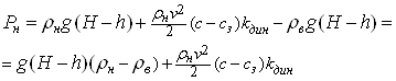
Then the total overpressure R n, Pa, formed in the outside air at a point at the height h of the building, is determined by the formula:
Figure 10 shows diagrams of the gravitational R gr, and wind Р wind pressures and the level at which the conditional zero pressure is accepted Р arb.
Each room creates its own total excess internal pressure, which is the sum of the pressure formed by various pressures on the facades of the building Р в, Pa, and gravitational pressure R gr, in, Pa.
Since the air temperature in all rooms in the building is approximately the same, the internal gravitational pressure depends only on the height of the center of the room h:
![]() (2.54)
(2.54)
where r in- density of internal air, kg/m 3 .
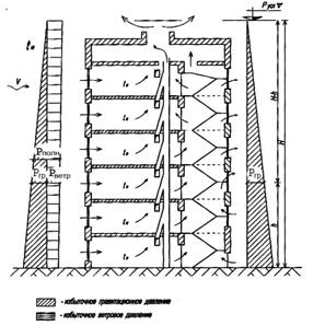
Fig.10. The formation of air currents in high-rise building with natural ventilation
For simplicity of calculations, the internal gravitational pressure is usually referred to the external pressure with a minus sign
 (2.55)
This removes the variable gravitational component outside the building, and therefore the total pressure in each room becomes constant along its height.
The air density ρ, kg/m 3 , can be determined by the formula following from (2.33):
where t is the air temperature.
The values of the internal total overpressure P in for equally oriented rooms of one floor may differ due to the fact that for each room its own value of internal pressure is formed. Determining the internal pressures in the premises is the task of a complete calculation of the air regime of the building, which is quite laborious. But to simplify the calculation, the internal pressure P in is usually equated to the pressure in the staircase.
There are simplified methods for calculating the internal pressure in a building. The most common calculation is valid for buildings with evenly distributed windows on the facades, when the conditionally constant internal pressure in the building is taken as the half-sum of wind and gravitational pressure according to the expression
The second, more cumbersome method of calculating the value of P in, Pa, proposed in , differs from the first one in that the wind pressure is averaged over the areas of the facades. The expression for internal pressure, when considering one of the facades as a windward one, takes the form:
where c n,c b,c s- aerodynamic coefficients on the windward, side and leeward facades;
A n, A b, A h- areas of windows and stained-glass windows on the windward, side and leeward facades, m 2.
When calculating heat loss, it is taken into account that each facade can be windward. Note that the internal pressure P in, taken according to (2.58), is different for each facade. This difference is the more noticeable, the more the density of windows and stained-glass windows on different facades differs. For buildings with a uniform distribution of windows along the facades, the value P in, approaches the one obtained from (2.57). Thus, the use of formula (2.58) for calculating the internal pressure is justified in cases where the distribution of light openings along the facades is clearly uneven or when the building in question is adjacent to the neighboring one, or one facade or part of it does not have windows at all.
The difference between the external and internal pressures on opposite sides of the fence on the windward facade at any height h taking into account formula (2.55) is equal to:
Pressure difference ∆P for windows of the same facade of different floors will differ only in the value of gravitational pressure (the first term), depending on the difference H-h marks of the upper point of the building, taken as a reference zero, and the center of the window in question. Figure 13 shows the pattern of flow distribution in a building with balanced ventilation
2.3.3 Air permeability of building materials
Construction Materials in their bulk are porous bodies. The size and structure of the pores in different materials is not the same, therefore, the air permeability of materials, depending on the pressure difference, manifests itself in different ways.
Figure 11 shows a qualitative picture of the dependence of air permeability G from pressure difference ΔР for building materials, given by K.F. Fokin.
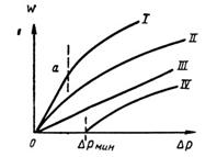
Fig.11. Effect of material porosity on its air permeability.1 - materials with uniform porosity (such as foam concrete); 2 - materials with pores various sizes(type of filling); 3 - low air-permeable materials (such as wood, cement mortars), 4 - wet materials.
Straight line from 0 to point a on curve 1 indicates the laminar movement of air through the pores of the material with uniform porosity at small values of the pressure difference. Above this point, turbulent motion occurs on the curved section. In materials with different pore sizes, the air movement is turbulent even at a small pressure difference, which can be seen from the curvature of line 2. In materials with low air permeability, on the contrary, the air movement through the pores is laminar even at fairly large pressure differences, so the dependence G from ΔР linear for any pressure difference (line 3). In wet materials (curve 4) at low ΔР, less than a certain minimum pressure difference ΔP min, there is no air permeability, and only when this value is exceeded, when the pressure difference is sufficient to overcome the forces of surface tension of the water contained in the pores of the material, air movement occurs. The higher the moisture content of the material, the greater the value ΔP min.
With laminar air movement in the pores of the material, the dependence is valid
where G is the air permeability of the fence or layer of material, kg / (m 2. h);
i- air permeability coefficient of the material, kg / (m. Pa. h);
δ - thickness of the material layer, m.
Air permeability coefficient of the material similar to the coefficient of thermal conductivity and indicates the degree of air permeability of the material, numerically equal to the air flow in kg passing through 1 m 2 of an area perpendicular to the direction of flow, at a pressure gradient of 1 Pa / m.
The values of the air permeability coefficient for various building materials differ significantly from each other.
For example, for mineral wool i ≈ 0.044 kg / (m. Pa. h), for non-autoclaved foam concrete i ≈ 5.3.10 - 4 kg / (m. Pa. h), for solid concrete i ≈ 5.1.10 - 6 kg / (m. Pa. h),
With turbulent air movement in formula (2.60) should be replaced ΔР on the ΔРn. At the same time, the exponent n varies within 0.5 - 1. However, in practice, formula (2.60) is also used for the turbulent regime of air flow in the pores of the material.
In modern regulatory literature, the concept of air permeability coefficient is not used. Materials and designs are characterized breathabilityR and, kg / (m. h). at a pressure difference on different sides ∆Р o = 10 Pa, which, with laminar air movement, is found by the formula:
where G is the breathability of a layer of material or structure, kg / (m 2. h).
The resistance to air penetration of fences in its dimension does not contain the dimension of air transfer potential - pressure. This situation arose due to the fact that in regulatory documents, by dividing the actual pressure difference ∆P by the standard pressure value ∆P o =10 Pa, the air permeability resistance is reduced to a pressure difference ∆P o = 10 Pa.
The values are given breathability for layers of some materials and structures.
For windows, in the leaks of which the movement of air occurs in mixed mode, the resistance to air penetration , kg / (m. h), is determined from the expression:
![]() , (2.62)
, (2.62)
Questions for self-control
1. What is the breathability of the material and fence?
2. What is breathability?
3. What is infiltration?
4. What is exfiltration?
5. What quantitative characteristic of the process of air permeability is called air permeability?
6. Through what two types of leaks is air filtered in fences?
7. What are the three types of filtration, according to the terminology of R.E. Brilinga?
8. What is the breathability potential?
9. What two natures form the pressure difference on opposite sides of the fence?
10. What is the air permeability coefficient of the material?
11. What is the air permeability of the building envelope?
12. Write a formula for determining the resistance to air penetration during laminar movement of air through the pores of construction materials.
13. Write a formula for determining the window's air permeability.
Heat transfer in building envelopes is a complex process involving convection, conduction, and radiation. All of them occur together with the predominance of one of them. The thermal insulation properties of the fence structures, which are reflected through the resistance to heat transfer, must comply with current building codes.
How is the heat exchange of air with enclosing structures
In construction, they ask regulatory requirements to the magnitude of the heat flux through the wall and through it determine its thickness. One of the parameters for its calculation is the temperature difference between the outside and inside the room. The coldest time of the year is taken as the basis. Another parameter is the heat transfer coefficient K - the amount of heat transferred in 1 s through an area of 1 m 2, with a difference in temperature between the external and internal environment of 1 ºС. The value of K depends on the properties of the material. As it decreases, the heat-shielding properties of the wall increase. In addition, the cold will penetrate less into the room if the thickness of the fence is greater.
Convection and radiation from outside and inside also affect heat leakage from the home. Therefore, reflective screens made of aluminum foil are installed on the walls behind the batteries. Similar protection is also made inside ventilated facades from the outside.
Heat transfer through the walls of the house
External walls make up the maximum part of the area of the house and through them energy losses reach 35-45%. The building materials from which they are made have different protection from the cold. Air has the lowest thermal conductivity. Therefore, porous materials have the lowest heat transfer coefficients. For example, for building bricks K \u003d 0.81 W / (m 2 o C), for concrete K \u003d 2.04 W / (m 2 o C), for plywood K \u003d 0.18 W / (m 2 o C), and for polystyrene boards K = 0.038 W / (m 2 o C).
In the calculations, the reciprocal of the coefficient K is used - the resistance to heat transfer of the building envelope. It is a normalized value and should not be lower than a certain set value, since heating costs and conditions of stay in the premises depend on it.
The coefficient K is affected by the moisture content of the building envelope material. In raw material, water displaces air from the pores, and its thermal conductivity is 20 times higher. As a result, the heat-shielding properties of the fence deteriorate. Wet Brick wall transmits 30% more heat compared to dry. Therefore, they try to line the facade and roofs of houses with materials on which water is not retained.
Heat loss through walls and opening joints is largely dependent on the wind. Bearing structures- breathable, and air passes through them from the outside (infiltration) and from the inside (exfiltration).