Voltmeter. Device, principle of operation, types and characteristics. Big encyclopedia of oil and gas
I welcome all readers to our website and today as part of the course " Electronics for beginners» we will study the basic ways measurement of current, voltage and other parameters of electrical circuits. Naturally, the main measuring instruments, such as voltmeter, ammeter and etc.
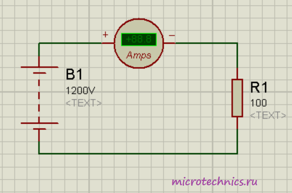
And we will start by measuring the current. The device used for this purpose is called ammeter and it is connected in series in the circuit. Let's look at a small example:

As you can see, here the power supply is connected directly to the resistor. In addition, there is an ammeter in the circuit connected in series with the resistor. According to Ohm's law, the current strength in this circuit should be equal to:
We got a value equal to 0.12 A, which is exactly the same as the practical result, which shows the ammeter in the circuit 🙂
An important parameter of this device is its internal resistance. Why is it so important? See for yourself - in the absence of an ammeter, the current is determined by Ohm's law, as we calculated a little higher. But with an ammeter in the circuit, the current will change because the resistance will change, and we get the following value:
If the ammeter were absolutely perfect, and its resistance was zero, then it would have no effect on the work electrical circuit, the parameters of which need to be measured, but in practice everything is not quite right, and the resistance of the device is not equal to 0. Of course, the resistance of the ammeter is quite small (since manufacturers strive to reduce it as much as possible), therefore, in many examples and tasks it is neglected, but do not forget that it still exists and is non-zero.
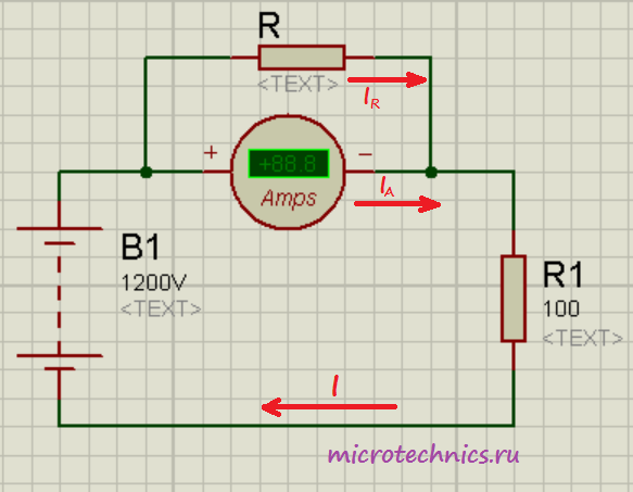
When talking about current measurement it is impossible not to mention a method that allows you to expand the limits in which the ammeter can operate. This method consists in the fact that a shunt (resistor) with a certain resistance is connected in parallel with the ammeter:
In this formula, n is the shunt coefficient - a number that shows how many times the limits will be increased within which the ammeter can make its measurements. Perhaps all this may seem not entirely clear and logical, so now we will consider a practical example that will allow us to understand everything.
Let the maximum value that the ammeter can measure be 1A. And the circuit in which we need to determine the current strength has the following form:
 The difference from the previous circuit is that the voltage of the power supply in this circuit is 100 times higher, respectively, and the current in the circuit will become larger and will be equal to 12 A. Due to the limitation on the maximum value of the measured current, we cannot directly use our ammeter . So for such tasks, you need to use an additional shunt:
 In this problem, we need to measure the current. We assume that its value will exceed the maximum allowable value for the used ammeter, so we add one more element to the circuit that will act as a shunt. Suppose we want to increase the measurement limits of the ammeter by 25 times, which means that the device will show a value that is 25 times less than the value of the measured current. We will only have to multiply the readings of the device by the number known to us and we will get the value we need. To implement our idea, we must put the shunt in parallel with the ammeter, and its resistance must be equal to the value that we determine by the formula:
In this case, n = 25, but we will do all the calculations in general view to show that the values can be absolutely anything, the principle of shunting will work the same way.
So, since the voltages on the shunt and on the ammeter are equal, we can write the first equation:
We express the shunt current in terms of the ammeter current:
The measured current is:
Substitute the previous expression for the shunt current into this equation:
![]()
But we also know the resistance of the shunt (). As a result, we get:
So we got what we wanted. The value that the ammeter will show in this circuit will be n times less than the current strength, the value of which we need to measure 🙂
FROM current measurements everything is clear in the circuit, let's move on to the next question, namely the definition of voltage.
A device for measuring voltage is called voltmeter, and, unlike the ammeter, it is connected to the circuit in parallel with the section of the circuit, the voltage on which must be determined. And, again, in contrast to the ideal ammeter, which has zero resistance, the resistance of an ideal voltmeter should be equal to infinity. Let's see what this is about:
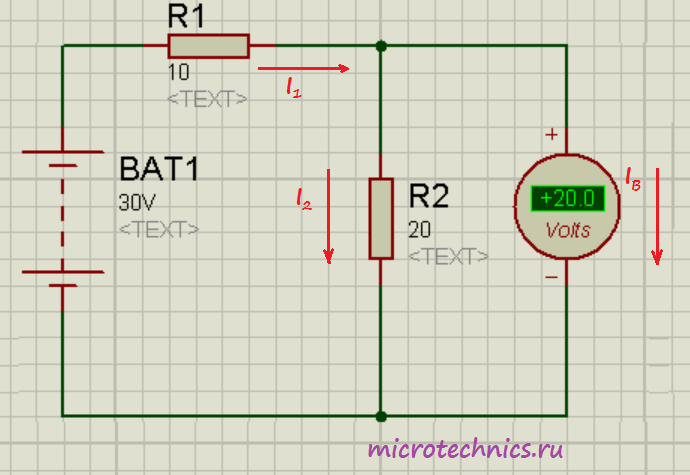 If there were no voltmeter in the circuit, the current through the resistors would be the same and determined by Ohm's Law as follows:
So, the current would be 1 A, and, accordingly, the voltage across resistor 2 would be 20 V. Everything is clear with this, but now we want to measure this voltage with a voltmeter and turn it on in parallel with. If the resistance of the voltmeter were infinitely large, then current () would simply not flow through it, and the device would not have any effect on the original circuit. But since it has a finite value and is not equal to infinity, a current will flow through the voltmeter and, in connection with this, the voltage across the resistor will no longer be the same as it would be in the absence of a measuring device. That is why such a voltmeter would be ideal, through which current would not pass.
As in the case of an ammeter, there is a special method that allows you to increase the voltage measurement limits for a voltmeter. To do this, it is necessary to connect an additional resistance in series with the device, the value of which is determined by the formula:
![]()
This will cause the readings voltmeter will be n times less than the value of the measured voltage. By tradition, let's look at a small practical example 😉
 Here we have added additional resistance to the circuit. We are faced with the task of measuring the voltage across the resistor:. Let's determine what will be on the voltmeter screen with this inclusion:
Substitute in this formula the expression for calculating the resistance of the additional resistor:
In this way: . That is, the readings of the voltmeter will be n times less than the voltage that we measured. So, using this method, it is possible to increase the measurement limits of the voltmeter 🙂
At the end of the article, a few words about measurement of resistance and power.
To solve both problems, it is possible to use an ammeter and a voltmeter together. In previous articles (about and) we dwelled in detail on the concepts of resistance and power and their relationship with voltage and resistance, thus, knowing the current and voltage of the electrical circuit, we can calculate the parameter we need. Well, in addition, there are special devices that allow you to measure the resistance of a circuit section - an ohmmeter - and power - a wattmeter.
In general, this is probably the end for today, stay tuned and visit our website! See you soon!
This is the device that you can not do without when working with electricity. It is used when it is necessary to measure EMF - electromotive force, as well as voltage in electrical circuits. The connection scheme of the device to the load is parallel.
Voltmeters, like any electrical instrument, must be regularly checked for compliance with specifications, repaired and serviced.
Determination of the technical characteristics of the voltmeter, types of voltmeters.
To determine specifications voltmeter the following indicators are taken into account:
- internal resistance. Well, if this figure is very high. This means that the influence of the device on the connected electrical circuit is reduced. And accordingly, the measurement with a voltmeter will be more accurate.
- The range of measured voltages is also the most important characteristic when measuring.
Standard voltmeter can measure voltage from millivolts to thousands of volts. But special voltmeters can also be used.
There are millivoltmeters and microvoltmeters that can measure the smallest voltage values, but retain high accuracy - up to millionths of a volt. And there are kilovoltmeters - devices for measuring very high voltage, up to 1000 volts.
To work with such devices, you need special skills and experience, access to the operation of electrical installations with a voltage of more than 1000 volts. This is necessary to avoid damage to devices when working with milli- and microvoltmeters or injuries when working with kilovoltmeters.
Measurement accuracy (error). With this parameter, you can set possible differences between the device data and the actual mains voltage.
Voltmeters and their classification.
The classification of voltmeters depends on their design, scope, and other parameters. Voltmeters are subdivided according to the following principles:
1. According to the principle of operation - voltmeters are divided into electromechanical (magnetoelectric and electromagnetic and electronic, for example, digital, analog.
2. For its intended purpose - for example, impulse, taking into account constant, alternating current and others.
3. According to the method of application - initially built-in (shield) and portable.
Greater sensitivity and hence accuracy magnetoelectric voltmeters. These devices are used more often in laboratories. The most common voltmeters are electromagnetic.
They are inexpensive, and their operation will not cause difficulties. Although they also have disadvantages - a fairly high power consumption, about 5-7 W, as well as a high inductance of the windings. Therefore, the frequency AC voltage leads to a significant effect on the voltmeter readings. Devices of this type are equipped in switchboards of power plants and industrial premises, objects.
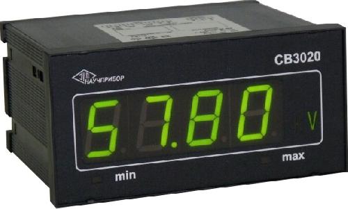
Electronic voltmeters divided into analog and digital. In analog devices, there is a scale and an arrow that shows the voltage value, moving away from zero. Such devices work as follows: the input AC voltage is converted to DC, increased and sent to the detector. After that, the output signal and leads to the deflection of the arrow. The more the arrow deviates, the stronger the input voltage.
When measuring voltage analog voltmeters it is important to observe the polarity of the connection of the device. With a negative voltage, the arrow will move to the left of zero, with a positive voltage, to the right. If the scale of your voltmeter does not have the ability to deflect the arrow in two directions, then you need to touch the point with the red probe that you previously touched with the white probe to measure negative voltage. Or vice versa (the colors of the probes may be different).
AT digital voltmeters indications of the voltage value are displayed on the electronic display.
Thanks to the scheme of universal voltmeters, it is possible to determine both direct and alternating voltage, depending on the installed operating mode switches and their position.
Measurements digital voltmeters will be more accurate than analog. The measurement is carried out by converting the analog input voltage into a digital code, which will be sent to a digital reading device, and then transforming the received binary code into a decimal digit, which will appear on the scoreboard.
The correctness of voltage measurement is due to the discreteness of the analog-to-digital converter included in the device.
Establishing the type of voltmeter by name.
To find out the type of voltmeter, its technical documentation is not needed. So, the first letter of the name of the voltmeter contains information about the type of device and the principle of its operation. The first letter "D" in the title means electrodynamic voltmeter; "M" - magnetoelectric; "C" - electrostatic, "T" - thermoelectric; "Ф, Ш" - electronic; "E" - electromagnetic; "C" - rectifier type voltmeter.
The name of radio measuring voltmeters begins with the letter "B". It is followed by a number that indicates the type of device, and through a dash - two numbers by which you can set the voltmeter model: B2, B3, B4 - direct, alternating or pulsed current devices. B5 - phase-sensitive voltmeters, B6 - selective; B7 - universal.
Safety precautions when using voltmeters.
The safety requirements are the same for all electrical appliances. When measuring voltage, it is important to correctly set the type of voltage being measured on the device. If the DC voltage is incorrectly set, then when connected to a circuit with an AC voltage available there, this device may break. In order not to be mistaken, you need to know the following.
DC voltage always comes with +27 V or -5 V. Also, AC voltage can be indicated by the ~220 V wave sign. Before the measurements themselves, it is necessary to determine the measurement range, this is very important. For example, if you need to investigate the presence of a voltage of +27 V, then you need to set: constant voltage, the measurement limits are greater than the measured voltage.
If the voltage indicator in the circuit is unknown, then set the maximum possible measurement limit. Then slowly decrease until readings appear. If you do the opposite, then the device will fail due to overvoltage.
They refer to measuring instruments with which you can control the magnitude of the voltage on a certain segment of the electrical circuit. Accordingly, the voltage measured by these devices has a unit of measurement Volt (V). Depending on the magnitude of the voltage, mi-, micro-, kilo- or mega voltmeters can be used.
Types of voltmeters
Let's take an example. To understand how this device works, we will classify them.
According to the principle of operation of voltmeters, they are divided into electromechanical (Fig. 1) and electronic (Fig. 2) devices. The first of them may have a magnetoelectric or electromagnetic measuring system. The second type of voltmeters is represented by analog and digital devices.
By purpose, devices can be divided into the following voltmeters:
- for alternating current;
- for direct current;
- impulse;
- multifunctional.
According to the method of use, voltmeters are manufactured as portable or built-in devices.
Fig.1 - Electromechanical voltmeter
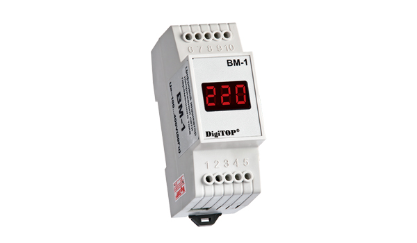
Fig. 2 - Electronic voltmeter
The principle of operation of voltmeters
Electromechanical devices
Voltmeters of this type incorporate a measuring system, which includes in its design a movable frame with an arrow-pointer attached to it and a measuring coil. The design of this frame resembles that used in an ammeter. The difference between how the ammeter and voltmeter work is that the ammeter is connected to a special shunt, and the measuring circuit of the voltmeter is connected directly to the place where the voltage is measured.
When the device is connected to an electrical circuit, a current passes through the coil of the measuring system, generating a magnetic field that interacts with magnetic field permanent magnet. Depending on the magnitude of the voltage, the arrow will deviate to a larger or smaller angle, indicating the magnitude of the voltage on the measuring scale of the device.
Electronic devices
To understand how digital works, it is important to consider what functional elements are included in it. These include: AC to DC Converter, Scalable Converter, DC/AC to Voltage Converter, Electrical Resistance to Voltage Converter.
The operation of such devices is based on the principle of analog-to-digital conversion of the current signal with push-pull integration. During the operation of the voltmeter according to this scheme, the input alternating (constant) voltage is converted into direct voltage, followed by its amplification and supply to the module, which provides visualization of the measurement data. In an analog device, an arrow with a scale is used as a visualization system, and in a digital device, a system for converting signals into digital codes, which are displayed on the LCD as a voltage value.
Fig. 3 - The principle of operation of the voltmeter
How to connect a voltmeter
To measure the voltage value, it is important to connect the voltmeter correctly. It must be ensured that it is connected to a segment of an electrical circuit or a voltage source in parallel. In this case, the high resistance of the voltmeter system will not affect the readings of the device. The current flowing through the voltmeter should be as low as possible.
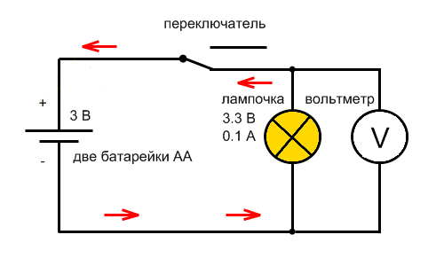
Fig. 4 - Voltmeter connection diagram
Key technical characteristics of voltmeters
To choose the right voltmeter for measuring voltage, you need to know its main characteristics. The main ones are the following.
The magnitude of the internal stress. This figure should be as high as possible. The greater the resistance of the voltmeter, the less influence it will have on the measurement readings, and the greater the measurement accuracy will be achieved.
measuring range. Depending on its value, the device can be used to control certain voltage values. There are versions of voltmeters that are designed only to work with low voltages - miles, or microvoltmeters, or to work with high voltages - kilo-, megavoltmeters.
Accuracy of measurements. This indicator indicates possible deviations of the measured value from the actual value.
Voltmeter- this is a device whose purpose is to measure the electromotive force (EMF) in a certain section of the electrical circuit, or more simply - voltage measuring instrument (electric potential difference). This device is always connected in parallel with the battery or load. The measured value is shown in Volts.
If we talk about ideal voltmeter, then it must have infinite internal resistance in order to accurately measure the voltage and not have a side effect on the circuit. That is why in high-end devices they try to make the internal resistance as possible as possible, on which the measurement accuracy and interference created in the electrical circuit depend.

Figure - Formulas for measuring voltage
If we talk about the method of installation, then they are divided into three main groups:
Stationary;
Shield;
Portable;
As the name implies, stationary devices are used where constant monitoring is needed, switchboard devices are used in switchboards and on dashboards, and portable devices are used in compact devices that can be used anywhere.
![]()
Figure - Voltmeter connection diagram
Everyone is divided according to purpose on the:
.Alternating current ;
.Direct current ;
selective;
Phase sensitive;
Pulse.
AC Voltmeters, as well as constant ones, are used for measurements in networks with the corresponding type of current, but selective ones can separate the harmonic component of a complex signal and determine the root mean square voltage value.
pulse voltmeter typically used to measure the amplitude of constant pulsed signals, and they are also able to accurately determine the amplitude of a single pulse.
Phase sensitive devices can measure the changes in the components of complex voltages, making it possible to accurately study the amplitude-phase characteristics of amplifiers, and other similar circuits.
According to the principle of action, they distinguish electronic(digital or analog), and electromechanical voltmeters(electromagnetic, thermoelectric, as well as magnetoelectric, electrodynamic and electrostatic).
All electromechanical devices, with the exception of thermoelectric ones, are, in fact, a conventional measuring mechanism with an indicating device. In all of them, additional resistances are used to expand the measurement limits. Devices of this category, despite the rather high internal resistance, have a relatively large error, which makes it impossible to use them in experiments and studies where increased accuracy data.
thermoelectric voltmeter uses for measurements the electromotive force of one or more thermocouples, which heat up due to the current of the incoming signal. They are more accurate and compact than electromechanical voltage meters.
Electronic, in turn, are divided into digital and analog.
Digital converts a constant voltage value into a digital signal, which is displayed on the instrument panel. This is done using an analog-to-digital converter.
In analog voltmeters, in addition to the magnetoelectric meter and additional resistors in without fail there is a measuring amplifier that allows several times to increase the internal resistance of the device, and, accordingly, to improve the accuracy of the readings.
Consider several different manufacturers
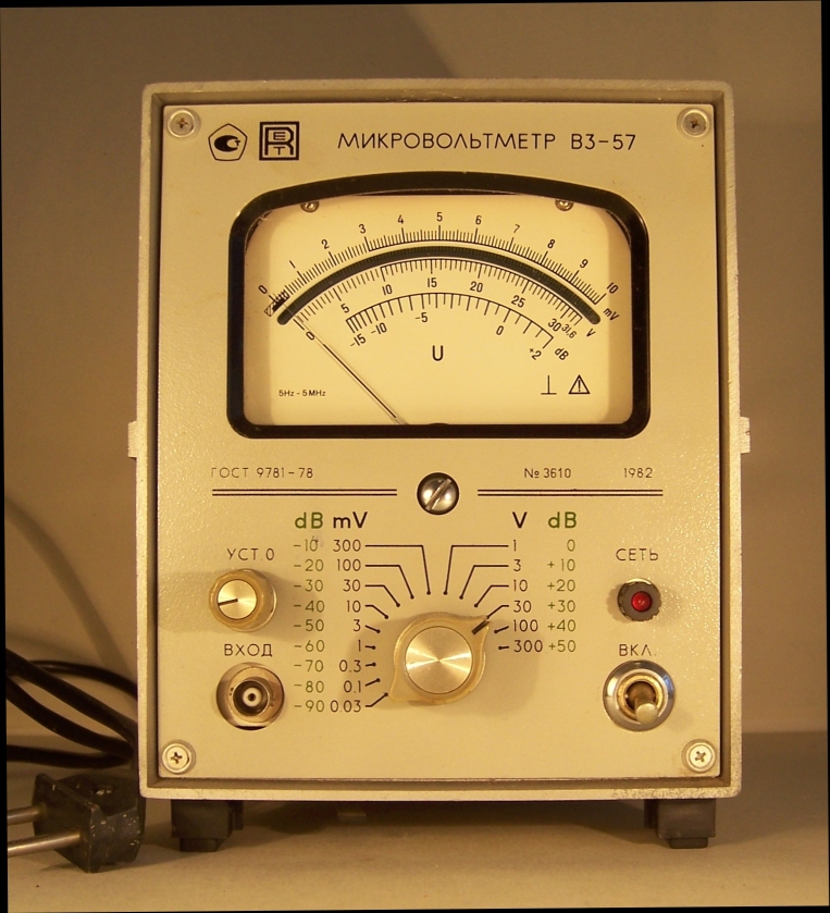 1. V3-57 - microvoltmeter
Measuring device model B3-57 - voltmeter-converter RMS. testimony. Designed for RMS measurements. values of voltages of arbitrary form and their linear transformation. in constant voltage. current. The scale of the device is marked in RMS. voltage values and decibels (from 0 dB to 0.775 V). It is used in the control and adjustment of various radio and teletechnical devices and communication facilities, the calculation of the frequency characteristics of broadband devices, the examination of noise stable signals, etc.
Main technical data:
Voltage measurement limits 10 μV - 300 V with boundary zones: 0.03-0.1-0.3-1-3-10-30-100-300mV 1-3-10-30-100-300V
Frequency limits 5 Hz - 5 MHz
Permissible error, %: ±1 (30-300 mV), ±1.5 (1-10 mV), ±2.5 (0.1-0.3 mV and 1-300 V), ±4 (0, 03 mV)
Input resistance 5 MΩ ±20%
Input capacitance: 27pF (0.03-300mV) and 12pF (1-300V)
The voltage at the output of the linear converter. 1 V
The resistance at the output of the linear converter. 1 kOhm ±10%
Limiting coefficient. signal amplitude 6*(Uk/Ux)

2. AC voltmeters AKIP-2401
RMS measurement of AC voltage
Frequency range: 5 Hz…5 MHz
Voltage measurement range: 50 μV ... 300 V (6 limits)
Two measurement RF inputs: CH1 / CH2
Maximum Resolution: 0.0001mV
Input signal level display in dBc, dBm, Upeak
Automatic or manual selection of measurement limits, holding the result (Hold)
Two-line VDF display
RS-232 interface
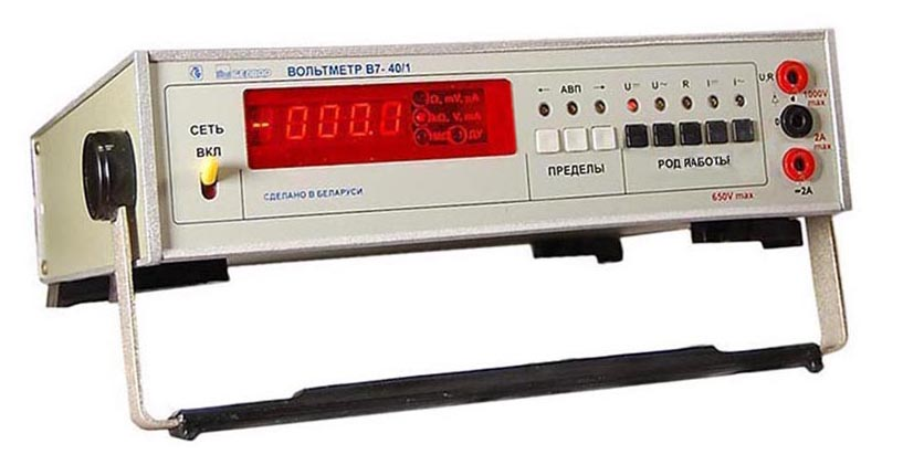 3. B7-40/1- high-quality digital universal device designed to measure DC and AC voltages, currents and resistance direct current. B7-40/1 is used in the production of radio equipment and electrical radio elements, in scientific and experimental research, in laboratory and workshop conditions. Built-in B7-40/1 interface IEEE 488 allows you to successfully use it as part of automated information - measuring systems.
The V7-40/1 voltmeter corresponds to severe operating conditions.
DC measurement accuracy of the V7-40/1 voltmeter - 0.05%
Maximum resolution B7-40/1 - 1 μV; 10 µA; 1 mΩ
Ranges 0.2; twenty; 200; 1000 (2000) V
- Resolution 1, 10, 100 µV; one; 10 mV
- Basic measurement error ± (0.04% + 5 ml. r)
Input impedance:
- on the range of 0.2 V not less than 1 GΩ
- on the 2 V range, at least 2 GΩ
- on the ranges of 200....1000 V, not less than 10 MΩ
Voltmeter, what is it? First of all, it is a device that serves as measuring device voltage values up to 1000V in direct and alternating current networks, industrial frequency and is used in information-measuring systems. An ideal voltmeter has an extremely high, infinite resistance, due to the large resistance of the device, the highest accuracy and wide scope of use are achieved.
The device is designed to provide mathematical and logical processing of measurements.
Types of voltmeters
There are two types of voltmeters:
- Portable or portable voltmeters designed to check (test) the voltage in the network. As a rule, such a device is included in the design of the tester, digital or pointer devices are distinguished, in addition to measuring voltage, they perform the function of measuring load currents, circuit resistance, temperature, etc.
If digital instruments differ in reading accuracy, then types of voltmeters, related to analog (pointer) devices, are able to respond to the slightest deviations of parameters that are not determined by a digital device. - Stationary devices installed on dashboards in electrical switchboards to control the operation of equipment, these devices belong to the electromagnetic type.
Voltmeter classification
Devices differ in the principle of operation, there are electromechanical and electronic.
By appointment, devices - pulse, measuring the network of direct and alternating current.
How to connect a voltmeter
The voltmeter is connected to the circuit in parallel with the load and voltage source, this is done so that the high resistance used in the device does not affect the readings of the device. The amount of current flowing through the device must be minimal.
Specifications of the voltmeter
Normal operation of the voltmeter is possible at an air temperature not exceeding 25 - 30 ° C relative humidity air up to 80% at atmospheric pressure 630 - 800mmHg Art. Power supply frequency 50 Hz and voltage 220V (frequency up to 400 Hz). The measurement is greatly influenced by the shape of the curve of the alternating voltage of the supply network - a sinusoid with a harmonic coefficient of not more than 5%.
The capabilities of the device are evaluated using the following indicators:
- device resistance.
- Range of measured voltage values.
- Measurement accuracy class.
- Limiting frequency limits of the voltage of the variable circuit.
The principle of operation of the device
The operation of the voltmeter is based on the method of analog-to-digital conversion with push-pull integration. Consider the operation of the device on the example of B7-35. Converters installed in the design, measuring the values of DC and AC voltage, current strength, resistance, are converted into a normalized voltage and, using the ADC, are converted into a digital code.
Functional diagram digital voltmeter works on using 4 converters it is:
- scaling converter.
- A low-frequency device that converts AC voltage to DC.
- Converter of direct and alternating current to voltage.
- Resistance to voltage converter.

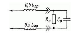
AC Voltmeter
Broadband electronic voltmeters used in AC networks have their own design features and their unique grading. The degree of impact on the measured circuit during the study depends on the complex input parameters, these are: the input active resistance (Rv), while the resistance should be the highest, the capacitance at the input (Cv), it should be as small as possible and the inductance (Lpr), it together with the capacitance creates a series oscillatory circuit, distinguished by its resonant frequency.
Measuring resistance with a voltmeter
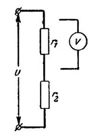
A low-resistance voltmeter with a resistance of not more than 15 ohms is suitable for measuring resistance and is performed using the formula:
Rx \u003d R and * (U1 / U2 - 1)
For the formula, the resistance of the voltmeter Rv is used, as well as 1 and 2 readings of the voltmeter, the measurement accuracy does not always correspond to reality, since the measurement is carried out without taking into account the internal resistance of the device. A more accurate result is achieved using the formula :
Rx \u003d (Rv + r) * (U1 / U2 - 1), internal resistance - r.
When measuring, each subsequent resistance must be large in terms of the resistance of the voltmeter and will be performed with the fixation of each measurement.
In order to determine what voltage the voltmeter shows, they are guided by the scale of the voltmeter, using the division value of the device. It is determined by the upper limit of the measured value, which is divided by the number of scale divisions.


