How to use a multimeter. General instructions, photo. A detailed description of how to use the multimeter correctly.
In today's article I want to tell you how to use a multimeter. We will use a digital multimeter, since it is much easier to master than its analog "colleagues" and provides quite tolerable quality of measurements.
Using a multimeter is easy! And now you will see it :)
A multimeter is also often referred to as a "multi-tester" because it is designed to take a fairly wide range of indicators: measuring constant and AC voltage, resistance and current strength. Many multimeters also have the ability to measure the gain of transistors and have a special mode for testing diodes, continuity for a short circuit, etc. In a word - " multi"(for a lot)" tester", in the people - a tension gauge! :)
If the measurement is the product of two measured values, the relative error is calculated by summing relative errors two measurements, if the measurement is the sum of two measured values, the absolute error is calculated by summing the absolute errors of the two measurements. Electrical measurements can be used with analog devices or digital devices. The main differences between these two types are summarized in the table below.
In both cases, the device is inserted into the circuit for measurement. The circuit is then modified to measure, and the instrument must change its behavior as little as possible. Digital gauges are not necessarily more accurate than analog gauges, but as seen above, they are obviously much more practical to use. For this reason, digital instruments are almost exclusively used in electronics, especially the multimeter, an instrument that can measure more quantities. Usually the tester can measure.
Expensive models like measuring devices include additional functions: temperature measurement (using a thermocouple probe), coil inductance, capacitor capacitance.
We have already touched on the topic of using this type of meter in an article called:. Now - let's analyze everything in a little more detail.
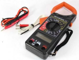
We will learn how to use a multimeter using the example of a Chinese-made budget device worth $ 10-15 " XL830L", which I use.
Continuous voltages AC voltages Continuous currents AC currents. . Some testers have other features such as. Capacitive capacitor capacitance measurement Transistor meter measurement Automatic temperature scale measurement. There are very cheap models on the market to very expensive ones, but almost all of them have the same look.
Of the four bushings, it is usually mentioned as they are used in all dimensions; others are used according to the size to be measured. Two cables are connected in the bushes, which connect the device with the measuring circuit. The terminal of these cables may have a different shape depending on the use, e.g.
To complete the picture, take a look at the analog (pointer) multimeter that my colleague uses:
So, let's take a quick look at the main characteristics of our digital multitester.
Its delivery set includes a set of simple "probes" (red and black wires in the photo above), with the help of which measurements are made. They, if necessary, can be replaced with better or more comfortable ones.
Voltage measurement - using the meter as a voltmeter
These operations should not be done hastily, because a mistuning of the instrument will result in incorrect readings, or worse, cause the instrument to break. For measuring voltage between two points in a circuit. Find a point with great potential, connect the red dot to this point and the black one to the other. This type of connection, shown in Figure 17, operates in parallel with the same voltage. The voltage in the head of the device actually coincides with two points in the circuit.
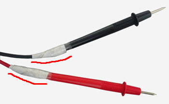
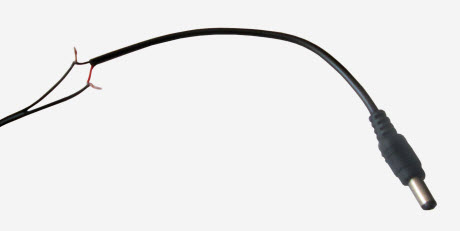
Note: be ready to immediately fix the entry points of both wires into the hollow plastic holder tubes with something (adhesive tape, electrical tape). The fact is that the conductors in the tubes are not rigidly fixed and when turning and bending the "probe" they can easily come off (due to the extremely flimsy solder) near the base of the measuring tip.
Current measurement - using the meter as an ammeter
This measurement is the simplest as it can happen without interrupting the circuit. Measuring current is more difficult than measuring voltage because the circuit must be interrupted to connect the instrument. To measure the current passing through the component you need.
The location of the current direction breaks the circuit, disconnecting one of the component's two terminal blocks, closing the circuit again, inserting a tool between the clip, disconnected, and the rest of the circuit. This type of connection, shown in Figure 18, is listed in series, which in electronics means crossing the same current. In fact, the device passes the same current that the component crosses.
Before you start using the multimeter in full, let's take a closer look at our digital tester:
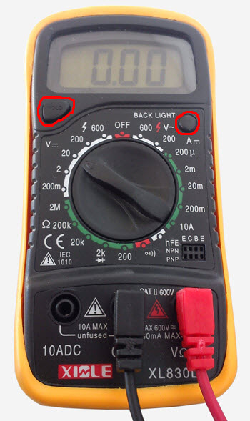
In its upper part we see a seven-segment digital display that can display up to four digits (9999 is the maximum value). When the battery is discharged, a corresponding inscription appears on it: “bat”.
Resistance measurement - using the tester as an ohmmeter
To measure the resistance of a conductor, simply connect its terminals to the multimeter terminals. An oscilloscope is a tool that allows you to display the waveform of a voltage signal on the screen, that is, to observe the change in voltage over time. With an oscilloscope, you can also take measurements, but you need to differentiate.
Analog oscilloscopes, where measurements are inaccurate because they are obtained only by observing the period and frequency of the grid, are two interchangeable quantities related to the repetition of an event; In function generators, the period specifies the time interval for repeating the function and frequency as many times as it repeats in the second. This website uses cookies to analyze visitor traffic. . Based on electrical resistance, conventional coils for transistorized ignition systems and mapped electronic ignition systems can be tested.
There are two buttons below the board. Left button " hold» - hold the readings of the last value (so as not to keep in memory when copying to a notepad). And on the right - back light» - backlighting the screen in blue (when measured in poor lighting conditions). On the back of the multimeter case there is a folding leg-stand (for convenient placement of the tester on the table).
Primary resistance measurement
The test is performed using a multimeter on a disassembled coil. The electrical resistance is measured in the primary and secondary zones. The primary resistance of the ignition coil is determined, for example, by the connection. Multimeter on terminals 15 and 1 of the coil. The following basic values apply to most working ignition coils.
Secondary resistance measurement
- Transistor ignition system: 0.5 - 2.0 ohm.
- Electronic ignition system with display: 0.5 - 2.0 ohm.
- Fully electronic ignition system: 0.3 - 1.0 ohm.
Powered digital multimeter 9 volt battery type "Krona". True, to get to it we will have to remove the rubber protective cover and the back cover of the tester.
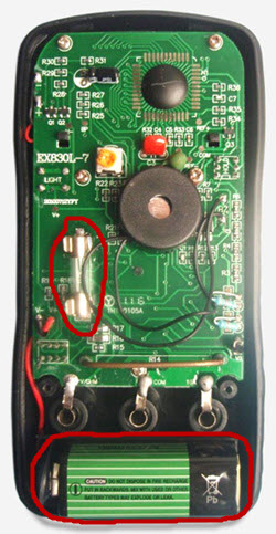
Circled in red at the bottom is our battery, and at the top is a fuse, which (I hope) will protect our meter from failure in the event of an overload.
- Transistor ignition system: 8.0 - 19.0 kOhm.
- Electronic ignition system with display: 8.0 - 19.0 kOhm.
- Fully electronic ignition system: 8.0 - 15.0 kOhm.
So, before you start using the multimeter, you must correctly connect the measuring "probes" to it. General principle here's the next one:
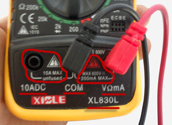
Black wire (it is called differently: general, com, common, mass) is a minus. We connect it to the corresponding socket of the multitester labeled " COM". Red - in the nest to his right, this is ours " a plus".
Measurement means comparing an unknown size with a known capture as a reference. The sample and the size to be measured must be uniform. Therefore, the measuring means determine the ratio or number of times that the reference sample will hit the measurement object. For example, if you want to know the length of the table, what is done is to check how many times a centimeter or a meter is included in the length. When we say that the length of the table is 230 cm, it means that our length of 1 cm is 230 times the length of our table.
Just like in the tablespace case, we see how many times our surface instance It hits the table surface. What is said extends to any length, be it length, area, time, or other. The measurement process, to be meaningful, must be such that it can be reproducible and not change the quantity to be measured; These two aspects, although seemingly trivial, are fundamental. To ensure a measure is reproducible, it must be at least our sample.
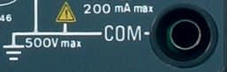
The remaining free socket on the left is for measuring direct current with a limit of up to 10 amperes (high currents) and - without a fuse, as evidenced by the warning inscription “ unfused". So be careful - do not burn the device!
Also note the warning sign (red triangle). Under it is written: MAX 600V. This is the maximum allowable voltage measurement limit for this multimeter (600 Volts).
Think, for example, of wanting to make a measure of length with a string and somehow make a measure of burning. At this point, saying that our table is 3 spaghetti long makes absolutely no sense, since we, as well as others, cannot use this measure. In particular, we have no way to pass the result of being able to turn the device into another. Having a well-defined pattern and reproducible is particularly important and different countries spend millions of euros every year to ensure that their benchmarks are kept intact.
As already mentioned measure in addition to being reproducible, in order to make sense should not change the magnitude of the measured. This means that the presence of our instrument along with the probes required for the measurement should not change the physical quantity being measured. Take for example, you want to measure the temperature of a shirt pin using a fever thermometer. fever thermometer is so much more than a pin to which the last quests will cool, changing the temperature we like to read.
Warning! Remember the following rule: if the measured values of voltage (Volts) or current strength (Amperes) are not known in advance, then to prevent the multitester from failing, set its switch to the maximum possible measurement limit. And only after that (if the readings are too small or not accurate), switch the device to a limit below the current one.
Therefore, it is clear that, according to the measurement and the specific system, it is necessary to use an approach that does not change the system under consideration. In other words, the measurement setting used to measure a certain size from a system may not necessarily be used to measure the same size in another system, but the size to be measured is the same.
Speaking generally about what a measure is, let's see what it means to measure voltage. The measurement of voltage is equal to the measure of the potential difference, i.e. is equivalent to measuring the potential at two different points and makes it a difference. For this reason, voltage measurement is always associated with the use of two terminals, which will be connected to the two points at which the voltage measurement is to be performed. From a physical point of view, a potential or better electrical potential is created when it is present. A field of forces associated with an electric field.
Now, in fact, - how to use a multimeter and how to switch these very "limits"? :)
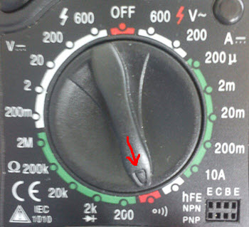
It is necessary to work with a multimeter using a circular switch with a pointing arrow. By default, it is set to " OFF» (device switched off). We can rotate the arrow in any direction and thus "tell" the multitester what exactly we want to measure or - with what maximum limit we will work.
It's good to talk about electric potential, because in nature you can have many types of vector fields, like thinking of a gravitational field. Voltage measurement is carried out using a voltmeter. The characteristic of the voltmeter should be to have an infinite input impedance or not subtract current from the circuit being measured. Figure 1 shows an ideal example of the voltage at the head of a resistor connected to another resistor in a voltage divider configuration.
Figure 1: Voltage measurement example. Figure 2: Voltage measurement example. Of course, in order to fix this error, you need to know that it happened. Whether or not the error should be ignored depends on the application and the accuracy you want to achieve, so you should always check that the paste error is less than what you are allowed to make. In doing so, you will realize that measuring voltage may not be as easy as thought. Before you see how to make a current measurement, it's good to remember what current is.
There is one here very important moment! Working with digital multimeter, we are able to measure values as variable, and permanent current and voltage. Now in industry and everyday life, the vast majority uses alternating current. It is he who "flows" through high-voltage lines of wires from generators of power plants to our homes, "lights" our lighting lamps and "feeds" various household electrical appliances.
Electricity is defined as an orderly flow of electrical charges, whether electrons or ions. The flow must be ordered because electric charges, like all particles in general, are always in continuous motion. However, their erratic movement does not result in an electric current given the randomness of the movement. The flow of electric charges can be ordered by applying electric field e.g. with a battery. At this point, defining the current as a flow, it is clear that the measurement electric current means accurate measurement of the ordered flow of electric charges.
Alternating current, compared to direct current, is much easier to convert (using transformers) into a current of a different (we need) voltage. For example: 10,000 volts can be easily converted into 220 and completely calmly directed to the needs of a residential building. Alternating current (compared to direct current) is also much easier to "extract" on an industrial scale and transmit it (with less loss) over long distances.
We move on. Inside the system unit is always flowing D.C. , since it converts alternating current (supplied to residential buildings from a substation) into low-voltage direct current (necessary to power computer components).
It is necessary to use a multimeter, given all of the above. Therefore, memorize the following abbreviations:
- DCV = DC Voltage - (eng. Direct Current Voltage) - constant voltage
- ACV = AC Voltage - (Eng. Alternating Current Voltage) - alternating voltage
- DCA- (eng. Direct Current Amperage) - current strength of direct voltage (in amperes)
- ACA- (eng. Alternating Current Amperage) - current strength of alternating voltage (in amperes)
Now, - we can learn to use the multimeter further. Take a closer look at the dial of your meter and you will definitely see that it is divided strictly into two parts: one for measuring DC and the second for AC voltages.
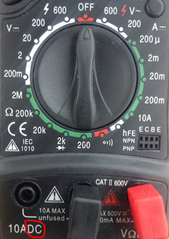
You see - two letters " DC» in the bottom left corner of the photo above? This means that to the left (relative to the “OFF” position) we will work with a multimeter, measuring constant e voltage and current values. Accordingly, the right side of the multitester is responsible for measuring the current variable.
Now I suggest you immediately consolidate the acquired knowledge in practice. Let's show an example of using a multimeter to measure the capacity of a conventional bios battery "CR 2032" with a nominal value of 3.3 Volts.
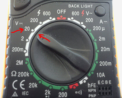
Remember our red warning? :) Always set the limit higher than the measured values. We know that the battery has 3.3V and this is a direct current. Accordingly, we set the "limit" of measurements on the DC scale to 20 Volts on the circular switch. As shown in the photo below.
Then - we take our galvanic cell (battery) and apply the measuring "probes" of the multimeter to it. Exactly like the photo below:
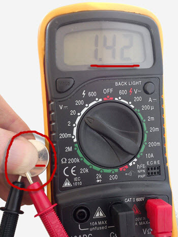
Pay attention to the red marked “+” sign on the battery. We apply a "plus" (red probe) to this side of it, and a "ground" (black) to the reverse side.
Note: if you confuse the polarity (to the plus - minus, and to the minus - plus), i.e. - swap "probes" in places - nothing bad will happen, just before the result on the digital display you will see a "minus" sign. The measurement values themselves will remain correct.
So, we used a multimeter and what is the result? Look (photo above) at the digital display of the tester. The numbers are shown there. 1.42 ". So our battery now has 1.42 Volts (instead of the prescribed three). With a swing of it - into the trash can! :) with such a battery, the computer will be automatically every time you turn it on.
For what other purposes (for the benefit of the Fatherland) can we use a multimeter? :) Here, for example, I recently needed to figure out how to properly connect an external USB connector to the old one, which is terminated with these four connectors:
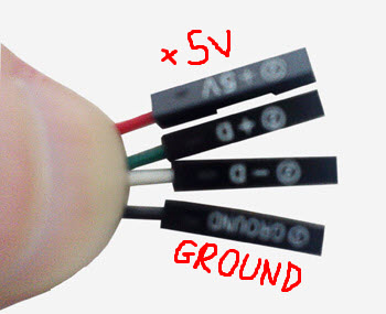
Here "+5V" is the supply voltage for the device connected to the connector, "ground" is "ground" and the two middle connectors are data cables.
First of all, we find contacts on the board (in this case, eight pins) for connecting USB. Look at the photo below:
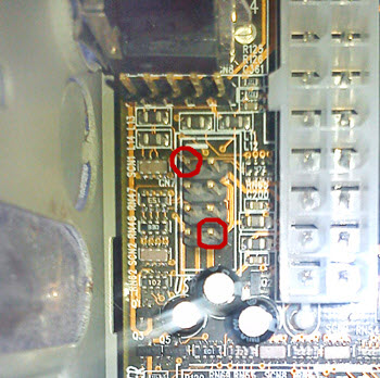
Each pin line is one USB output connector. In total - two. For the correct connection (so as not to burn the device plugged into the final connector), it is important for us to know which of the "pins" is energized? We can pick up the rest using the "scientific poke" method, but if we put the data connector on a 5-volt "pin" and connect a USB flash drive to such a bunch, then it will immediately come crashing down! :)
Therefore, it is necessary to use a multimeter with a clear understanding of what and why we are doing. Measurements by the tester, of course, are made with the computer turned on. We press the "start" button and apply the black "probe" of the multimeter to any place of the metal (otherwise we simply will not see the results on the screen). Then, with a red "probe", we begin to consistently touch all the "legs" of the connector on the board, following the readings of the multimeter on the screen.
Attention! touch the measuring "probe" pins carefully so as not to short-circuit two at the same time of them (this way you can burn the USB controller itself on the board).
Following this scheme, we found out that five Volts are located on the two extreme contacts (see photo above). We turn off the computer and begin to gradually fill our connector. First, we put on the contacts marked "+ 5V" on the designated pins, two data cables - immediately behind them and the last - a connector with the inscription "ground".
Visually check if everything is in order and turn it on again. We take a flash drive and insert it into one of the two USB ports that we just connected to motherboard. The LED on the "flash drive" lights up (power is on), and after loading operating system we see that we connected the data cables correctly, since the removable disk is successfully detected by the system!
For those who are not tired of all this technical "crap" yet, I suggest moving on :) In order to learn how to use a multimeter and work effectively with it, we need to know (remember, write down, memorize, tattoo) :) the following designations, which we will probably meet on similar meters, regardless of their model.

More advanced samples of multimeters also show the capacitance of the elements - “ F"(it is measured in Farads) and inductance -" L» (calculated in Henry - "Gn").
I suggest that you quickly "walk" through the entire multimeter dial and consider all of its pointers and functions. For ease of use, let's do this: open in a new window and look at the picture as you read the text, referring to the switch positions.
We will move from left to right. So, in the "OFF" position, the multimeter is completely off. The next switch position is 600 Volts on the scale variable current. It is the best suited for measuring the voltage in a household electrical network (the current is alternating and the scale value is several times higher than the required one - 220 V.).
Let's check this statement in practice!
Attention! Voltages in 200 and 600 Volt - life-threatening! Therefore, when working with them, be extremely careful and careful!

The order of the "probes" in the outlet does not matter.
The next position is 200 Volts (you don’t need to measure the voltage in the outlet on it - the multimeter is on fire! ). To the right we have the number "200" with the icon " µ » (microampere - millionth of an ampere). Similar values of quantities can be used in various kinds of electrical circuits.
The next on the scale is "2m" (two milliamps - two thousandths of an ampere). The indicator is found mainly in transistors. Further - "200m" - similarly, but the countdown starts from two hundred milliamps. The next switch position is "10A" ( maximum strength current - ten amperes). This is the territory of high currents, be careful! Here we will need to include the red "probe" into a special socket, indicated in the photo as " 10ADC».
You can also successfully use a multimeter to measure the "hFE" values of transistors of various conductivity (NPN and PNP transistors). Let's check one of them:
As you can see, the three "legs" of the element are simply inserted into the corresponding sockets on the multimeter. We will not expand on this type of measurement now (we still have a website on computer topics), but remember, just in case:
- B - base (base)
- C - collector
- E - emitter
Acoustic wave (continuity) line icon for a short circuit. What use is this to us? Let's look at an example. At the same time, I'll show you a couple of interesting photos :)
Photo one - the last stage of the final part of the final stage on one of the floors at our place of work! :)

One hundred stranded cables dangling from cable ducts anchored in a false ceiling space.

Imagine such a situation (as it turned out - very real) that some of the cables were forgotten to be signed. It turns out the following: on the other wing of the building (at the user's computer socket), we cannot say which one a cable out of a hundred belongs to this specific ending and the search for a "happy ending" automatically turns into a separate task :)
This is where the mode of using the multitester as a "dialer" of the cable for a short circuit will come to our rescue. Since the hint itself is contained in the name, the following remains for us - to organize this very short circuit ().
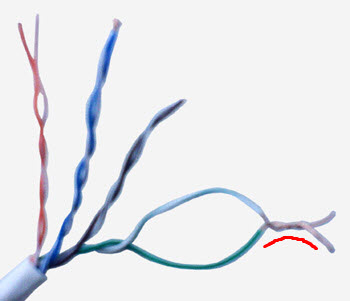
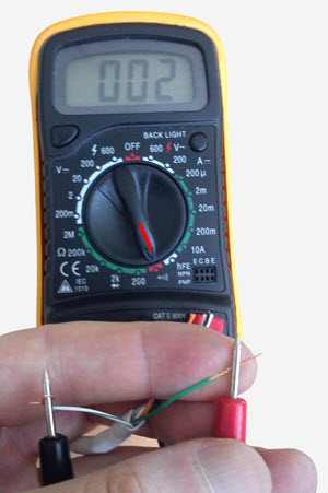
In low-voltage networks (which include computer LANs), this is not at all scary :) At the ends of the cables on both sides, we remove the protective coating, select one specific cable (which we want to find (ring out)) and also clear any pair of its conductors from insulation. And then - just twist them together, creating a "loop" in the line. By God, it's faster to show in the photo than to describe in words :)
Now we go to our "noodles" hanging from the ceiling, and move the multimeter switch to the position we need:
We begin to "ring out" each of the unsigned cables. Naturally - we choose pairs the same color that and twisted by us at the other end of the line! And I guarantee you that one of the tested cables will respond to our efforts with a characteristic "squeak", since, thus, we have finally closed the line, and the limit of the multimeter's sound signal is 70 ohms. And if the resistance between the probes is less than this value, then the tester emits a specific high-frequency sound signal.
The order of applying the "probes" is not important. Of course, this is such an "express method" of using a multimeter, it would be more correct and reliable to install a resistor at the remote end of the cable, and measure the resistance of the resistor through the line with a tester from our side. But, in the conditions of the situation described above, the first method is faster. Well, sometimes it's just too lazy to bother :)
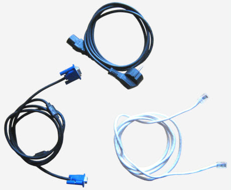
Let's work out an elementary procedure: we'll ring the cable for a break. We will explore three different types cables:
- crimped network cable (patchcord)
- VGA cable to monitor
- power cable computer
Let's check if there is a break in our patch cord? To do this, we apply one multimeter probe to the first core in the first connector, and the second to the same core in the second. At the same time, we translate the meter itself into the "ringing" mode.
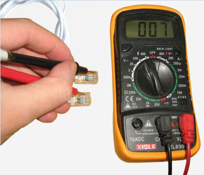
Note Note: The probes must be thin enough to reach the copper strips in the RJ-45 connector.
If we did everything correctly, we will hear the characteristic sound signal of the tester, which indicates that the conductor is closed and there is no break. In the event of a break, of course, there will be no signal. So sequentially check each pair of conductors.
Next in line is a VGA cable for transmitting a signal from a video card to a monitor. Let's check it out too! To do this, we apply one probe of the multitester to one of the pins in the first cable connector, and the second one to the symmetrical pin in the second connector.
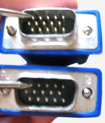
We touch only the pin itself. If we apply a "probe" to the inside of the connector housing, then an audible signal will be heard regardless of which of the pins we short on the other side of the cable.
And now - let's call the power cable of the computer for a break. To do this, one of the "probes" of the tester (no matter which one) is inserted into the connector at one end, and the second measuring "probe" is applied to one of the terminals of the electrical "plug" of the cable.
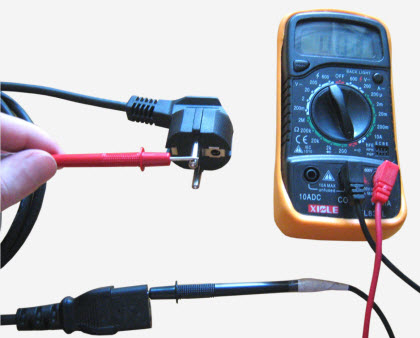
The middle hole is the ground. As in the previous examples, with one of the combinations, we should hear a beep.
Note: all these tests can also be carried out in the resistance measurement mode, but, as we have already said, this option is the simplest and most time-saving. In most cases, I recommend choosing it.
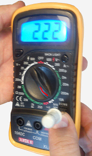
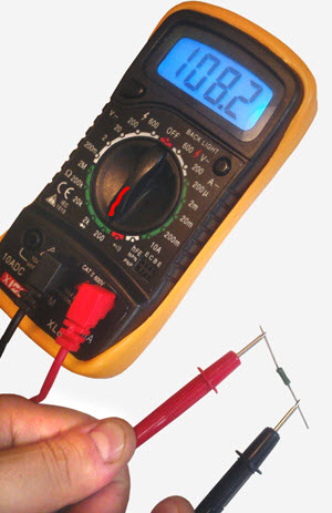
You can also use a multimeter to determine the resistance values of electrical components. We enter the resistance measurement zone (English "resistance" or R, it is indicated by this icon and is measured in Ohms). The first value on the switch is "200 ohms". You can, for example, measure the resistance of a resistor. Let's do that!
We take a 110 ohm resistor and measure its resistance:
Next - there is a switch with which you can "ring out" the diode without soldering it from the printed circuit board. The multimeter, in this case, will calculate the resistance value from the voltage drop of the component.
It is followed by positions in "20k" (20 kiloohms or 20 thousand ohms), "200k" (200 kiloohms - 200 thousand ohms) and "2M" (two megaohms - 2 million ohms).
Next - the voltage measurement thresholds on the DC scale: "200m" (200 millivolts - 0.2 Volts), "2", "20", "200" and "600" Volts. As we already understood, if you use a multimeter exclusively for computer repair, then the most popular switch position is the position in " 20 » Volt scale direct current, since the maximum voltage supplied to all components is only 12 V.
Note: you can read the article on how to use a similar tester to check some elements on the PC motherboard.
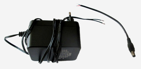
Let's take the final push and I'll show you how to use a multimeter to test your DC power supply. We often have the following task at work: to transfer the shank (connector) from one such power supply to another. It is implied that the power supply unit is from cheap network switches, and other electronic rubbish. Here, for example, is such a 12-volt instance, to which you need to screw another connector:
To begin with, we take the connector cable itself and “probe” it with a tester in the dialing mode:
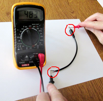
Pay attention to where the "probes" of the device are located: one is on the bare end of the cable, and the second is on the outer metal bypass of the connector. How is the connector set up? One cable goes to the ground (this very bypass), and the second to the pin inside. The fact is that it is this outer rim that is the "ground" (minus or "mass") in similar power sources.
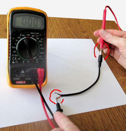
If the multimeter beeps, then we have found our cable, if not, we move the black probe (when dialing, their order does not matter) to another wire. Having thus determined the "earth" cable (we can mark it so as not to forget), we find our "plus" in the same way. To do this, we insert one of the probes inside the connector itself (we should also hear a beep):
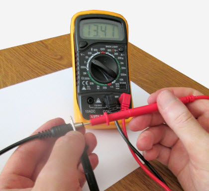
So, using a multimeter helped us determine the plus and minus (ground) of the tail cable. Now we need to deal with the same moment applicable to the power supply itself. We insert it into the socket (do not be afraid, you are unlikely to feel 12 volts), put our device into the DC current measurement mode with a limit of 20 Volts and attach the probes to the wires coming from the PSU.
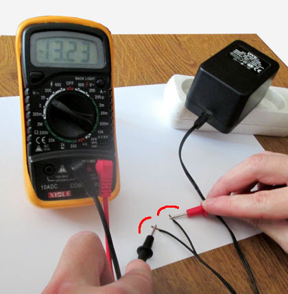
Lyrical digression: we do this because we need to determine the polarity, i.e. on which wire the power supply has “+”, and on which “-”. As we remember, when working with sources, we must strictly observe the polarity! You can practice on a regular battery :)
So, in the photo above on the multimeter display, we see a minus sign. What does it mean? Remember! The display shows the polarity where the red contact is connected. The absence of a minus sign is treated as a plus! Based on this, the red probe of the multimeter is pressed against the "minus" of the power source. Swapping the pins:
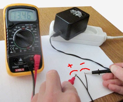
We see that the result is shown on the scoreboard without the “-” sign, which means that we correctly determined the polarity (“plus” of the PSU on our red wire). Do not pay attention to the value of more than 12 volts on the instrument panel. Under load, it will "sag" to its legal 12 volts.
Now, knowing the polarity, we can correctly twist two wires together.
We connect the whole thing to an outlet and make a test measurement on the connector of the resulting design.
Note: Sometimes the connector is too narrow and the tip cannot be inserted into it. In this case, a straightened paper clip is used, which is inserted inside, and a probe is already applied to it.
Everything is fine. Now we can safely use a soldering iron to isolate them and connect the power source to the desired device.
I hope I didn’t “bored” this article very much and you endured it to the end? If so, then congratulations! Now you definitely need to know how to use a multimeter! :)
Finally, watch a video on how a twisted pair network cable is crimped. How to properly arrange the conductors in the cable, we discussed with you in one of our courses.
Hello!
The article will be long, so get ready. You can read it in several visits. As articles are added, some of the material will “roam” to other articles, and links will remain here.
So, you have chosen a multimeter, thanks to my previous , and now you want to learn how to use it. I must say right away that there is nothing complicated when working with a multimeter. The main thing is to plug the measuring probes into the “correct” sockets and correctly set the measurement function and its limit.
Consider two of the most suitable models for newbies.
How to use the DT-830B multimeter
An inexpensive technical solution that has the most common measurement functions. Suitable for household infrequent use. I will not consider the limits of measurements, since there are a lot of them on the Internet. Well, I’ll tell you how to measure after reviewing another model. Several modifications are produced. Modification means adding different functionality. The inconvenience of this model is that if the measurement mode is set incorrectly, there is a possibility of burning the multimeter, so you need to use it very carefully. In general, he is very capricious about bullying his person.
How to use the DT-266 multimeter
You probably immediately noticed the orange pincers at the top of the device. This device does not have as wide functionality as the previous model, but it has the function of measuring variable
current (up to 1000 amperes) and a special prefix is \u200b\u200bproduced for it, which allows you to “turn it into a megger. And it also has a “hold” button - a button for holding results, which is located at the top of the right side wall. If pressed during a measurement, the display will freeze the measured value and reset only when the hold button is released.
The "hold" button can be located in unexpected places, for example, in the center of the switch (as on this model), which is not always convenient, since accidental pressing is possible. If your multimeter suddenly “stopped” working, that is, the numbers on the display froze and the measurement results are not displayed, take a closer look: the “h” or “hold” icon may appear on the display, which will mean that the button to hold the results is pressed.
When you decide on a model, carefully pay attention to the letter index in the model name when buying in a store. For example, model DT-830 is the base model. The letter or the last digit with a letter in the model name is responsible for its additional features: dial tone, signal generator, various measurement limits, temperature measurement, etc.
On sale there is a set of probes with special tips, which are convenient to use in different situations. It can be "crocodiles", clips, terminals, needles and much more.
How to use a digital multimeter
Well, now let's start learning. For example, let's take the long-suffering DT-830B. The image is clickable, meaning you can click on it to enlarge it. And first, let's look at how to prepare it for work.
 In the lower right part there are sockets for installing probes. The black probe is always installed in the "COM" jack.
Depending on what you want to measure, the red probe is installed either in the “10ADC” socket ( in this case, the measurement limit is 10A. On the multimeter, this position and the socket are circled in red) and measurements up to 10 amperes are possible only in this switch position. Important feature: when measuring current, the probes close to each other inside the device, that is, if you try to measure voltage in this way, you will cause a short circuit. If you disassemble the multimeter, you can see that the "10A" and "COM" sockets are interconnected by a thick wire. ALWAYS REMEMBER THIS. ) The maximum current value that can be measured in this way is 10 amperes (for this multimeter), and the abbreviation ADC means that only direct current can be measured. When measuring AC voltage, nothing will be shown on the display.
Measuring ranges and limits
The second socket for the red probe "VΩmA" means that you can measure:
- V - volt (voltage)
- Ω - om (resistance)
- mA - milliamper (current in milliamps).


