Types of building columns with cranes. Types of steel columns of one-story industrial buildings
Federal Agency for Education
Kazan State University of Architecture and Civil Engineering
Department of technology, organization and mechanization of construction
COURSE PROJECT
"DEVELOPMENT OF TECHNOLOGICAL MAP"
« Installation reinforced concrete columns
single storey industrial building
In addition to normal loads such as building self-weight, snow and wind loads, etc. Buildings can be designed for girders, overhead cranes, and future extensions that support existing columns. The calculation of the structure is carried out using a computer, achieving with a special program the full accuracy and technical rigor of all the data that must be taken into account.
The walls are formed by several sections, which are connected together with a high-strength screwdriver, with none of the components being welded in the assembly. This property, which can be extended to other components of the building, allows them to be completely restored and, if necessary, can be moved to a new location.
Completed: Art. gr. 11-3s
Nesterova E.R.
Checked by: Mavlyuberdinov A.R.
Kazan - 2009
1 area of use.
2. Organization and technology of the construction process, works.
4. Calculation of the cost of a pile, the operating time of machines and mechanisms, wages.
5. Work schedule.
6. Material and technical resources.
Determine how much and what different types buildings. Determine how many and what different buildings. materials and sizes. along with their characteristics. Determine the materials that will be used to build each type of building. Specific purposes: defining their use.
The execution of the structure must be designed and planned taking into account the current and future needs of the company. Production areas and management areas need to be taken into account. designed and subsequently built to effectively meet the needs of the type of industry for which it was designed. either new or reconstructing an existing one. required for optimal performance. Plant Buildings Multi-Plant Buildings These buildings are beneficial where gravity circulation in processes is required. where land is limited. requires consideration of the following factors: Current and future needs of the company Financial situation General economic conditions Changes in the market Municipal rules and regulations that affect the building itself.
8. Technical and economic indicators.
9. List of used literature.
1 area of use.
The technological map was developed for the installation of reinforced concrete columns of a one-story industrial building in summer time of the year.
Console columns.
Installation in a glass type of foundation using a conductor.
L = Building length - 72 meters
Building classes Planning the construction of an industrial building. Their floors may be clad in layers of liquid cement or carpeted granite. asbestos cement. Their ceilings and mezzanines can be made of reinforced concrete slabs. This type of structure is dominated by structural steel with a combination of reinforced concrete in smaller quantities. Most of them are area reinforced concrete structures and area of production of metal structures. There should be a gardening area and parking for visitors and employees. or some sections reinforced concrete slab function dependent environment. aluzinc plates. areas for loading and unloading goods. which are: First category.
B = Building span - 18 meters
Section of columns - 0.4 m * 0.4 m;
Column length - 9.8 m;
Beam bottom mark - 8.4 m
Technical documentation for the organization of construction processes is drawn up in the form of technological maps, which are standard and compiled; for the construction of a particular facility. Typical technological maps usually make up for the performance of work during construction according to standard designs and, when used, require clarification (binding) taking into account construction.
Its main structure consists of rigid beams and columns of reinforced concrete and reinforced concrete aggregates that transfer their forces to individual blocks of the same material. Floors for production area It is unheated reinforced concrete. For the office. as well as the availability of service and sports grounds for employees. The top roof of a building can be made of zinc foil. External and internal walls- brick or brick. sheet. waterproof and easy to clean. These buildings usually consist of two parts: an office area and a production area. which are supported by beams and columns of the same material.
Table 1. List of volumes of technological operations
2. Organization and technology of construction process, work.
Installation of columns using a conductor .
Installation of structures begins only after a thorough instrumental check of the marks and position in terms of supports, supporting and embedded parts. The installation process has a decisive influence on the overall duration of construction and the organization of subsequent work. The installation of columns is carried out in the direction along the span of the building. With a span width of more than 18 m, the crane, moving along one of the rows of columns, installs this row of columns, mounting one or two columns from one parking lot, returns and mounts the column from one parking lot, returns and mounts the columns of another row. It is not advisable to install columns of the second row, because will delay the installation of other structures due to insufficient strength of the joints. The conductor allows you to automate the process of aligning columns and apply the forced installation of CE in the design position. The installation of columns is usually carried out by self-propelled jib and tower cranes. columns industrial buildings they are mounted by first laying them out at the place of installation, or directly from the vehicles by which they are served in the area of the installation crane. From vehicles, columns are mounted by turning on weight.
Types of buildings There are three types of buildings in which production activities take place. with a finish that provides them with a smooth surface. Buildings are classified according to the materials used for their construction. since the latter will serve as a support for steel columns and fillers. These types of buildings are usually used to house all the staff and equipment that are part of the districts and administrative departments. their strength and type depend on the manufacturing process. the latter being of the prestressed concrete type. wood and brickwork.
Installation of columns .
Columns delivered to the construction site are laid out so that during installation the necessary movements and the amount of auxiliary work are minimal, so that free access is provided to the columns for inspection, attachment of equipment and slinging. The columns are laid out not flat, but in such a way that during the lifting process the bending moment from the weight of the column and equipment acts in the plane of the greatest rigidity of the column (especially this must be taken into account when installing two-branch columns).
The third category Wood is the material that intervenes mainly in the construction of these buildings. Disadvantages: Although steel is a non-combustible material in direct and continuous fire. Maintenance costs are high. like the previous ones. When the clearings are small, instead of armor, wooden beams. which support the top cover, which may be zinc sheet. Demolition costs are low, making installation changes economical. Walls and internal partitions can be brick or wooden. or asbestos, and in some cases a corrugated sheet of waterproof cardboard.
Before the column is lifted, its length is measured with a steel tape measure, the distance from the lower column to the plane of the crane console or, in the absence of such, to the plane of support of the coating elements is checked. If the measured distance is less than the design one, then the bottom of the foundation glass should be “poured” with cement mortar or steel linings should be installed.
Windows and doors are made of wood. They are easy to assemble and fast. this risk can be reduced by installing suspended sprinklers. Advantages: Supported loads can be high. They are wide in their interior making them ideal for heavy industrial processes. Because it has such a prefabricated type. expenses for Maintenance. its main elements can be sold at any given time. reduces resistance and deforms elements with probable destructive defects.
Benefits: Your construction cost is the lowest of the three. therefore increases. since its main structural elements are made of prefabricated structures. that operate at a certain temperature. from reinforced concrete. These buildings usually consist of a single plant dedicated to the production area and it has space for a small office. must have an employee service area. They are structures susceptible to vibration. the interior of the building is practically at the mercy of the weather.
The installation of the column begins after the leveling layer of cement mortar in the foundation glass has gained at least 70% of the design strength.
In addition, before lifting, axial risks are applied to the four faces of the column, as well as risks of the axes crane beams.
The installation of the column is carried out by an independent flow. The crane moves along the span and sets 2 columns from one parking lot.
They are easy to assemble and disassemble. There are several types of structures. As a rule, the area they occupy is small. Due to low structural strength and limited market size. have different shapes, and for their construction different types of materials are used. Due to their shape, lamps can be added. no calculation in its implementation. Zinc or asbestos sheet does not support thermal insulation and both bolts are for fixing. as well as the placement of fans for lighting and ventilation.
Its installation is quick and removable. Bases are light and do not require precision. It is necessary to implement a program of prevention of structures. therefore, there may be galvanic corrosion, and it is required that the sheet be painted periodically. because the seams have nails or screws and the elements are light. but they all have the same purpose, which is to distribute loads evenly. in order to achieve greater stability, taking into account the weight of the covered objects that they must support. The roof needs two main elements: the roof and the structure.
The column installed in the foundation glass is centered until the marks coincide with the risks on the upper plane of the foundation glass.
To check the verticality of the columns, two theodolites are installed at right angles to the digital and alphabetic axes of the building. In this case, the cross of threads is directed at the risks applied on the glass and the lower part of the column, and then, smoothly raising the theodolite tube, at the risk at the upper end of the column.
Roof types Ceilings used in industrial buildings. The cost of maintenance is very high due to the durability of the wood. Its curved shape acts as an insulator. Curved ceiling. Its installation is very fast and less maintenance is required as the material to be used for the cover is zinc sheet. It is more expensive and cannot be easily taken apart. The amount of material that will be used for installation is more than other types of roofs.
It requires a lot of preventive maintenance, and the asbestos or zinc sheet does not contribute to thermal insulation. There is no galvanic corrosion because it is an assembled and unpunched sheet. there is a loss of space on its longitudinal sides. Cannot be used in places with too much space between columns. It is removable and also its shape allows you to use natural ventilation. It is very aesthetic and has an aerodynamic shape. making full use of natural light. in addition, their supporting walls must be extremely stable, as they must resist the horizontal forces acting on the roof. therefore, the columns impede the passage and distribution of the plant.
The leveling of the planes at the ends or consoles of the columns, on which the truss structures and crane beams are installed, is carried out according to the marking marks or along the rail suspended from the leveled plane.
The verified columns are fixed in the foundation glass with the help of conductors or steel, wooden and reinforced concrete wedges. Reinforced concrete wedges are not removed when aligning the column and sealing the joint with a concrete mixture, but are left in the concrete. Wedges are installed two at each side of the column with a width of more than 400 mm.
Buildings of the second category. Top ratings of buildings. Buildings of the third category Figure. Roofing from zinc sheet or asbestos cement. fillers. Plant buildings have enough space and are more flexible for the distribution of objects in the same. Multi-storey buildings very useful for processes requiring gravity circulation. also very favorable when there is not enough space or the cost of it is very high. According to the materials used in the construction of buildings, they can be divided into three types. rustic concrete floors.
The materials used in construction are used various types buildings. smooth concrete floors. The tree is used for the third category. first category. concrete plates. For structural steel of the second category. reinforced concrete foundations. for the structure of the first category of beams and columns of reinforced concrete fillers. top sheet cover made of zinc or asbestos.
Rice. 7. Means for alignment and temporary fastening of columns in foundation glasses: a - design scheme; b - conductor diagram; c - wedge insert; g - jack mechanism
As a rule, the lower columns are installed on glass-type foundations, aligned and fixed in them, like the columns of one-story buildings. And the columns of subsequent floors are already installed on the upper ends of the columns located below, or on crossbars.
Consider the lifetime of a project before deciding on the type of building to be used. as some types are easily destroyed while others are not. Take into account the needs of the production process carried out in the building so that it is most adequate. Consider what process will be going on inside the building to decide if maintaining it is a priority and choose a type that supports that need.
Typology of production or industrial construction. Industrial building. These elements are ideal for building bridges with reduced construction costs and execution programs, quality improvement, cleaning and aesthetics. There are several sections that can be used as bearing beams, of which they can also function as stiffeners. It is used in the construction of viaducts, road bridges and pedestrian crossings. It is easy to install and avoids road obstacles and overlaps in place. The toe of the beam varies depending on the polarization and the type of load required. The beam has a large top flap to improve negative moment strength in solid sections and is designed to accommodate a large number threads. This is especially useful when using high strength concrete. Due to its size, it can be transported to almost any site, one of the advantages of which is the saving of the overall turnaround time. The dimension of the load is designed for each work by the designer in accordance with the loads on the board and its shape. The prefabricated connection plate has permanent sections and distribution steels to support each other and unique panels. Its placement is very simple, the concreting of the slab should cover the armor along with the protruding prefabricated expectations, which are complemented by cages. The width of the excavation at the bottom is greatly reduced. The excavation profile is implemented in two sections, being much more stable than any structure. The lower part of the panel is supported on the foundation leg, which is carried out in the first assembly operation. The plateau was built after filling between prefabs and before excavation. In this way, the team is supported on a slope which, with its weight, is sufficient to counteract the thrust of the filling lands. Each prefabricated element is provided with a connection reinforcement that is built into the plateau, which is provided with steel and other additional expectations, folded into work and made from the same prefabricated. Its shape, construction and technology allow the builder to perform quality work and get a faster construction. Rectangular Column This is a precast piece of reinforced concrete with a wide range of sections. Round Abutment Round precast concrete abutments are commonly used in parking spaces because the space is used to prevent corners. Its manufacture requires a more complex process. Concrete brackets from ready-mixed concrete. Ready-mix concrete brackets include: "short" brackets: they are small ledges that support some other element, such as the start of an arch, balcony, or deck. "Long" or cantilever brackets: elements which, in their function of horizontal length, are like a beam, that is, by bending. Among other applications it is worth mentioning: Structures: especially with important horizontal traction by means of braking, soil pushing in stirrups, long spans, etc. And also for important bending forces transmitted by the structure to the base of the foundation, Buildings with high height or located in a seismic zone: where there are significant bends and shear stresses in the foundation, especially when loads are transferred through shielded poles, elevator screens, etc. The rest of the foundation can be made with precast concrete piles. The joints are made from high quality materials, further enhancing the performance than the pile section itself, as evidenced by various bending, compression and tensile tests. All of the elements that make it up are completely covered in concrete and protected from the environment, with the exception of the outer sheet, which has no structural function once the pile is clogged. In addition, all connecting elements are embedded in an anti-corrosion lubricant and the components are adjusted so that after combining the various elements, a pre-tension is created that ensures ideal stress transfer. Typically used in standard buildings with loads that do not have of great importance for transmission to land or with good land quality. It needs a well aligned base to support the shoes, they are made in different sizes according to the manufacturer. Usually the measures range between 1 m and 3 m of base and between 80 cm and 2.50 m of height. They are manufactured at the factory, transported and assembled on site on a flat concrete base. The abutment is stabilized inside the shoe and the bond to the concrete is firmly fixed. This results in: lower foundation costs. Reduce the cost of structure, both metal and concrete. Significant reduction in assembly time. Reduce construction time. These panels are located maximum size in horizontal and vertical directions. They unload their weight on the base brackets or another panel if they are simply screwed on or on suspension brackets if they are suspended. They can be screwed in when they extend beyond the structure or when the panels pass between the columns between the channel. The horizontal hull is the most common way to place a prefabricated hull given its versatility with prefabricated elements or any other type of structure. These tablets are prefabricated elements in the plant through extrusion or continuous casting processes. According to its features of use, section T allows great freedom in the design of their works. The T section is made from metal or concrete and metal molds that may or may not be self-reinforcing, steam generating, therefore daily casting cycles, in order to improve productivity. The design and manufacture of these products make the boards elements of great versatility in the works to adapt to a wide and long requirement from a project.
- These types of products are used to support mezzanine slabs and roofs.
- From the foregoing, it is convenient to use this section of buildings of several levels.
- It is not recommended to use this section as a stiffener.
The installation, alignment and temporary fixing of columns are practiced in the following three ways:
Installation according to risks with vertical alignment with a plumb line and welding of parts of butt joints. To ensure the verticality of the columns during alignment, if necessary, braces are used. This method is used when installing columns with platform-type joints. It can also be used when mounting columns with milled steel plates at the ends, but then temporary fastening is performed with bolts, for which corners are welded to the embedded parts in advance;
Installation of columns on the heads of the columns, on which single conductors are pre-fixed with screws (the heads of the lower columns are usually 0.5-0.8 m above the floor level). The column installed in the conductor is fixed with adjusting screws and aligned along the center axes and vertically. Apply various designs single conductors;
Installation of columns on the heads of the lower columns with temporary fixing and alignment with the help of group conductors for four columns. The group conductor is installed and fastened with clamps to the heads of the columns installed below. Each of the four columns is installed, fixed and aligned in the same way as installations with single conductors. Flooring with railings at the top of the conductor allows you to mount floor structures. After the installation work is completed and the elements are fixed in one cell of the building, the conductor is moved to the next cell. The conductors are lifted to the next floor by a crane.
The most common group conductor is a frame-hinged indicator (RSHI). RSHI is a device consisting of spatial lattice scaffolds, on which there is a hinged (floating) frame with corner stops for fastening four columns at once in the upper position, retractable and rotary cradles for assemblers and welders. At the corners of the frame for temporary fastening of columns in the design position, angular faceted clamps (stops) are installed - two swivel and two folding, which can occupy a transport or working position and do not interfere with the installation of crossbars and plates.
With the help of such a conductor, the columns are mounted without additional alignment. They are lifted one by one, brought by a crane to the corresponding clamps of the conductor and smoothly lowered onto the heads of the underlying columns. The side edges of the bottom of the mounted column are fixed with a tensioning device of the lower latch fixed to the column head, pulling it close to the sides of the latch. In this way, their exact alignment with the corresponding faces of the column head is ensured. The top of the column is fixed with an upper grip - indicator frame lock, bringing the column to a strictly vertical position.
Casting joints and reinforced concrete structures:
Monolithic joints and seams with a mortar or concrete mixture are carried out after verifying the correct installation of structural elements, acceptance of welded joints and anti-corrosion protection of steel embedded parts and reinforcing bars. Concrete or mortar mixture is fed into the joint under pressure or in a free-mechanized way or manually. The process of filling joints and seams with mortar and concrete mixture consists of supplying and laying mortar or concrete mixture into the seams, followed by compaction.
Work organization of workers:
The organization of labor of workers in construction includes the appropriate placement of people in the production process, the division into labor cooperation, methods of rationing and stimulating labor, the organization of jobs, their maintenance and the necessary conditions labor. The scientific organization of labor requires constant improvement of labor processes on the basis of the latest achievements of science and practice, aimed at a steady increase in labor productivity, improvement of conditions and improvement of work culture, and the transformation of labor into a vital need.
The scientific organization of labor is created on the basis of a complex of technical, organizational and economic measures that ensure the most rational division and cooperation of labor, improvement labor processes and organization of jobs.
Methods of organizing labor can be different depending on the structures used, methods of work, machines, installations and other means of production.
To perform various operations in the construction process, workers are grouped into units, depending on the nature of the operations that need to be performed by the unit or team. The links usually consist of two or three workers of the same profession, but with different qualifications.
Several links performing the same construction process are combined into a team headed by a foreman.
Brigades are specialized and complex. The composition of a specialized team includes workers of the same specialty, up to 25 people. Complex brigades unite workers of different professions to perform a specific set of works, part or whole structure. The complex team includes approximately 50 workers.
A team of final products is organized for the erection of individual structural elements (foundations, walls, ceilings, etc.) or the building (structure) as a whole.
Every year the number of teams of workers performing work by the method of team contracting on the basis of cost accounting increases. Both the brigades of the general contracting organization and the subcontracting organization are transferred to the brigade contract. The transfer of teams to economic accounting should be preceded by the development of work schedules, the supply of basic materials, structures, products to the facility, the compilation of labor costs and wages, and the determination of the cost of work assigned to the team.
One of important indicators The activity of construction workers is labor productivity, i.e., the amount of working time spent per unit of output, defined in man-hours or man-days. The lower the cost of labor in man-hours per unit of output, for example, per 1 m3 of brickwork, per 1 m2 of plastered surface, etc., the higher labor productivity.
Construction processes at the construction site or part of the facility are carried out in a certain order (combining in time), ensuring the rhythm of production and the most rational use of labor and technical means. The object is divided into areas, i.e. areas where there is a sufficient amount of work to complete the construction process by the team for a certain time (usually at least one shift). The number of grips should be sufficient so that teams of different professions can perform construction processes at the same time, moving from one grip to another after finishing work. For some processes, the grip is divided by height into tiers, for example, when brickwork, which cannot be immediately completed to the height of the floor and which requires the construction of a scaffold, The part of the grip allocated for work by one link of workers is called a plot.
The space in which the workers involved in the production are located, as well as the machines, materials and parts necessary for the construction process are located and moved, is called the workplace. The area allotted for the work of a brigade or link for a certain period is called the front of work. The size of the scope of work determines the size of the team involved in the construction process. The scope of work is measured in units of length, area or volume. For the correct organization of complex construction processes at the facility, technical documentation is developed, which determines the nature of the process and its composition, production methods and means of mechanization of works, calendar schedule of production, required amount workers by profession and their qualifications, materials, parts, tools and organization of the workplace.
Sometimes the construction object is conditionally divided vertically into technological tiers. The need for such a division arises when design features object, the front of work opens in the process of their execution. For example, when concreting columns by lowering the concrete mixture from above, while the height of the tier according to SNiP should not exceed 5 m in order to avoid delamination of the concrete mixture during its fall.
Table 2. Qualification composition of a brigade or link
| link number | Running processes | Qualification composition of workers | Number of workers |
| 1 | Installation of columns in the foundation glass | Structural assembler of the 5th category | 1 |
| 1 | |||
| Structural installer 3rd category | 2 | ||
| Structural installer 2nd category | 1 | ||
| Crane operator 6th category | 1 | ||
| 2 | Sealing joints | Structural installer 4 category | 1 |
Structural installer 3 |
1 |

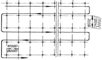
Rice. 1.1 Scheme of unloading and preliminary layout of columns in buildings with a span of 12, 18, 24 m.
1 - Foundation glass; 2 - column; 3 - vehicle; 4 - crane; 5 - traverse.


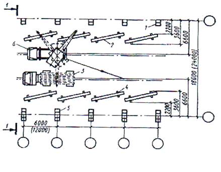
Rice. 1.2. Scheme of installation of columns in buildings with a span of 12, 18, 24 m:
1 - foundation glass; 2 - column; 3 - vehicle; 4 - crane; 5 - traverse.
Alignment and temporary fixing of columns is carried out with inventory wedge inserts or conductors. Moreover, for columns weighing 8 tons, the conductor is installed on the foundation and fixed on the column after it is installed in the foundation glass. For heavier columns, conductors are installed, aligned and fixed on the foundation before the installation of the column.
After installing a number of columns, their design position is finally verified and the joints of the columns with the foundations are sealed. Columns for embedding are rented out in batches.
Scheme of installation of one-story industrial buildings :

The columns are delivered to the construction site by road, while light columns (weighing up to 8 tons) are mounted with preliminary layout at the installation sites in the area of the assembly crane, and heavy ones are delivered to the assembly crane according to an hourly schedule and mounted directly from vehicles.

Rice. 1.3. Schemes of crane movement when installing columns in spans of 12, 18, 24 m.
Rice. 1.4. Scheme of unloading and layout of crane beams with a span of 6 and 12 m:
1 - column of the extreme row; 2 - crane beam; 3 - bulk carrier; 4 - wooden lining; 5 - column of the middle row; 6 - truck crane; 7 - brace on a hemp rope; 8 - sling.
Depending on the span (12; 18; 24m or more) and the pitch of the columns (6; 12m), various schemes erection of columns and movement assembly cranes(Fig. 1.2, 1.3, 1.4).
It is advisable to mount crane beams in an independent flow directly from vehicles. The installation of beams in the design position is carried out according to axial risks on the beams and consoles of the columns. The beams are temporarily fixed to the supports with anchor bolts. The final alignment of the crane beams is carried out within the mounting grip or temperature section, using geodetic tools, after which all fasteners of the beams and embedded parts of the columns are checked.
Methods for laying out columns before installation: a - light; b - heavy;

For the installation of light columns of one-story buildings with jib cranes, a fork head, made in the form of a cantilever attachment to the head of the boom, which has blocks for reeving ropes, can be used. The headband is equipped with a device for semi-automatic slinging. It allows the use of cranes with a shorter boom length and, therefore, better use of their lifting capacity. In addition, the minimum suspension length reduces the swing of the column and allows their carrying capacity. In addition, the minimum hanger length reduces column sway and improves installation accuracy.
If necessary, the bottom of the glass is leveled with a layer of cement mortar. The columns are installed in the foundation glasses after the strength of this solution reaches at least 70% of the design. Alignment and temporary fixing of columns, depending on their size, weight and installation location, is carried out using individual conductors of inventory steel, wooden, reinforced concrete wedges (two at each side of the column).
The column installed in the foundation glass is centered until the marks coincide with the marks on the upper plane of the foundation.
To check the verticality of the column, two theodolites are placed at right angles to the digital and alphabetic axes of the buildings. In this case, the visual axis of the theodolite is combined with the risks marked on the glass in the lower part of the column, and then, smoothly raising the theodolite tube, with the risk at the upper end of the column. The distance outside the theodolite from the column being verified is taken such that at the maximum rise of the pipe, its angle of inclination does not exceed 30-35 '.
The planes at the ends or consoles of the columns are leveled according to marked marks or along a rail suspended from the leveled plane.
The verified columns are fixed in the foundation glass with the help of conductors.
Warehouse design
Warehousing of prefabricated structures is carried out in stacks or cassettes, in which structures working in a vertical position are placed - Wall panels, farms, etc.
The aisles between the stacks are arranged with a width of 0.4 to 1 m and are arranged through 2 stacks in the longitudinal direction.
Aisles with a width of 3 ... .4 m for the movement of vehicles and handling mechanisms are arranged at least every 100 m.
The width of the warehouses is taken from the calculation that all elements rise from the warehouse without additional re-edging and movement, i.e. they must be within the range of service cranes.
In the warehouse, prefabricated elements are placed in the same position as on vehicles during transportation. Horizontally stacked structures are laid on wooden linings, the distance between which is linked to the operating conditions of this structure.
The layout of elements in the warehouse can be separate, in which all elements of the same type are stored together, and group, when the layout and installation of elements of different types is provided from one parking of the assembly crane.
Construction site roads
Construction roads include access roads that connect the construction site to the general road network, and internal construction roads that transport goods within the site. Access roads, as a rule, are made permanent, and internal roads before the construction of the main facilities.
Roads at construction sites can be dead-end and roundabouts. At the end of dead ends there should be turnarounds, and in the middle part, if necessary, sidings. Based on the standard size of the car (rectangle 2.5 m wide and 3.8 m high), the width of the carriageway of the road with a single lane is 6 m. not less than 6 m.
When using heavy machines, the carrying capacity of 25 ... 30 tons or more, the width of the roadway increases to 8 m. If large and long loads are delivered to the construction site, the width of the road can be further increased.
The radius of curvature of roads is dictated by the ability to maneuver individual vehicles and road trains, i.e. their turning ability when moving forward without using reverse gear. Usually, the minimum radius of curvature is taken as 15 m, in this place the width of the carriageway is increased - with a road width of 3.5 m at the rounding, it will be 5 m.
Structurally car roads consist of subgrade and pavement. To drain surface water, the road is given a double slope on straight sections of the track, and a single slope on curved sections.
The pavement consists of several layers - the underlying sandy layer, the bearing base (crushed stone, concrete, reinforced concrete) and the coating. To reduce the costs for the construction period at the construction site, it is advisable to build future permanent roads without top coating. Only the lower layers of the road are suitable, it is even more efficient to lay a temporary coating of reinforced concrete road slabs on a sandy base. The main coating in this case should be carried out before putting the facility into operation.
As reinforced concrete road slabs, rectangular and wedge-shaped slabs are used. Rectangular road slabs (2.5 ... 3.0 m long, 1.0 ... 1.5 m wide, 0.14 ... 0.22 m thick and weighing 0.63 ... 1.8 tons) are easy to manufacture and working with them on the construction site, they can withstand increased loads, they are suitable for use immediately after their laying at any time of the year and in any weather. Roads are more often arranged with track - one - and double-track with sidings. Wedge-shaped slabs make it possible to cover the roadway immediately for the entire width of the road, the radius of curvature on turns can be any. On straight sections, the plates alternate, placing them either with a wide or a narrow side. For such slabs, there is no need for the construction of individual sections of the road (especially on bends) in a monolithic design.
The cost of building, repairing and maintaining such roads under conditions of typical traffic intensity for construction sites usually pays off in 1.5 ... 2 years. Prefabricated - collapsible slabs are the property of the construction organization and require their repeated use.
Loading and unloading construction materials
Transportation of building materials to the facility is associated with the need to load them at the place of departure and unload at the place of arrival. These operations are almost completely mechanized; general construction and special machines are used to perform them, or they are part of the design of vehicles.
The first group includes special assembly cranes, cyclic and continuous loaders, mobile belt conveyors, mechanical shovels, pneumatic unloaders, etc. The second group includes dump trucks, vehicles with self-unloading platforms and autonomous unloading facilities, etc.
In construction, the transportation of small-piece materials and products using packages and containers is used. A package is a consignment of cargo laid on a special pallet. Packages must be formed in such a way that their shape is preserved at all stages of the movement.
A container is an inventory reusable device or container. The universal container is designed for transportation of various categories of cargo; it is closed, equipped with devices for loading and unloading. Special containers are designed to transport a certain type of cargo - roll materials, finishing tiles, linoleum, electrical fittings per building section, etc.
Warehousing of material elements
The material elements delivered to the construction site are stored in on-site warehouses intended for their temporary storage - the creation of a production stock.
There are two main types of production stock - current and insurance. The current stock constitutes the material resource between two adjacent deliveries. Ideally, the current stock should be sufficient to ensure the continuous production of work. However, taking into account possible disruptions in the supply of materials and structures, they create an insurance stock, which should smooth out, compensate for the uneven replenishment of the current stock. The minimum stock of prefabricated structures in the warehouse is usually taken for 5 days of work.
The level of production stock depends on the accepted organization of work - installation "from wheels" or from a warehouse, the remoteness of the object from the central supply bases, the type of transport and other factors. The presence of a warehouse with an excessive stock of structures or materials, on the one hand, ensures uninterrupted production of work, and on the other hand, leads to a "freeze" of investments in this construction, i.e. to its rise in price. Therefore, the general contractor is obliged to find the optimal volumes of on-site warehouses. On-site warehouses are arranged as closed, semi-closed and open.
Closed warehouses are used to store expensive or spoiling materials in the open air - cement, lime, gypsum, plywood, nails, etc. They can be aboveground and underground, one-story and multi-story, heated and unheated.
Sheds - semi-closed warehouses are erected for materials that do not change their properties from changes in temperature and humidity, but require protection from direct exposure to the sun and precipitation - wood products, asbestos cement, roofing felt, and other enclosing and finishing materials.
Open warehouses are designed for storage of materials that do not require protection from atmospheric influences - bricks, concrete and reinforced concrete elements, ceramic pipes, etc. Warehouses, as a rule, are located in the area of the assembly crane serving the object. This allows it to be used for unloading incoming goods, mainly in free time or in shifts free from installation. During installation, it is advisable to use lighter self-propelled cranes for unloading operations.
Part of the open warehouse, including the site for pre-assembly of structures, can be serviced by special cranes - self-propelled on caterpillar and pneumatic tracks, gantry, tower cranes - loaders. These mechanisms are used for loading enlarged structures onto vehicles for their subsequent delivery to the places of laying or installation. Typically, in a warehouse, heavy loads are placed closer to the cranes, and light loads further away, as they can be lifted at a longer reach of the crane.
Storage areas should be flat, with a slight slope within 2 ... 5% for the flow of storm and melt water. On poorly draining soils, it is recommended, in addition to planning, to carry out a small addition of crushed stone or sand - 5 ... 10 cm. If necessary, carry out surface compaction. Sections of the storage area, where materials (mortar, sand, etc.) are unloaded directly from vehicles, should be made in the same constructive solution as the adjacent access roads.
For different designs and prefabricated products, they allocate their own storage areas. They are separated from one another by through passages with a width of at least 1 m. For various materials There are rules for warehousing.
Brick is stored according to grades, brands, color of the front surface. Brick delivered in bulk is stacked with dressing and up to 1.6 m high, while the brick with non-through voids is down. Bricks in packages or on pallets can be stacked in a warehouse in one or two tiers.
Precast concrete is placed on inventory linings and gaskets, the laying places of which must correspond to the risks on the prefabricated elements. When storing elements in a stack, the spacers between them are stacked one above the other strictly vertically. The cross section of gaskets and linings is usually square, with a side of 6 ... 8 cm. The dimensions are selected so that the overlying elements do not rest on the mounting loops or protruding parts of the underlying elements.
Before installing columns:
Concrete or install foundations for columns and check their compliance with the design position using geodetic instruments;
filling up the sinuses of the foundations;
· apply the risks of the installation axes on the upper face of the foundations and the side faces of the columns;
close the glasses of the foundations with shields to protect them from pollution;
arrange roads for the passage of a crane and cars;
· to prepare platforms for warehousing of columns at the place of their installation;
· Deliver the necessary installation tools, fixtures and tools to the installation area.
Reinforced concrete columns at the facility they are laid out on wooden linings in the area of the assembly crane. The thickness of the pads must be at least 25 mm.
In the absence of mounting loops, the columns are slinged with a noose loop in the places indicated at the factory. The rope must not have knots or twists. To protect the rope from kinks and rubbing, steel linings should be placed under the ribs of the columns.
Each column must be inspected so that it does not have deformations, damage, cracks, shells, chips, exposed reinforcement, concrete sagging; check the geometric dimensions of the column, the presence of a mounting hole, the correct installation of steel embedded parts.
For alignment and temporary fixing of columns, a set of mounting equipment is used, placed in a container. The kit includes inventory wedge inserts and other devices (RF-595 TsNIIOMTP).
Artists:
· Worker performing installation work, senior in the link;
Worker performing installation work;
· Worker performing rigging work.
Work production technology
Preparing the column for installation (Fig. 13), the performer is a worker performing rigging work

Preparing the column for installation .
Rigger
1. Checks column markings.
2. Cleans the ends of the column from the influx of concrete and dirt with a metal brush.
3. Using a metal meter, divides one plane in width into two equal parts in two places (at the level of the top of the foundation and at the top of the column) and draws axial risks with a pencil.
4. Using similar techniques, he inflicts risks on the second plane perpendicular to the first.
5. Gives a signal to the crane operator to apply the universal gripper 3 to column 2.
6. Puts on the grip from the upper end of the column and, using the inventory handle, tightens the nuts of the clamping device.
7. Departs at a distance of 7 ... 8 m from the column.
8. Gives a signal to the crane driver to raise the column to a height of 200-300 mm.
9. Inspects fasteners.
10. Gives a signal to the crane operator to move the structure to the installation area
Preparing the installation site
Installers 1st, 2nd
1. The 2nd installer lays out the tool, fixtures, inventory.
2. Then he checks the cleanliness of the foundation glass.
3. After checking the risks on the upper plane of the foundation glass.
4. The 1st and 2nd installers lay out the tools and fixtures according to the scheme for organizing the workplace.
5. The 1st installer installs and aligns two theodolites.
Reception, installation and fixing of the column
Column alignment with a single jig
Installers 1st, 2nd

Rice. 16. Scheme of alignment of the column with jacks:
1 - worker performing installation work, senior in the link, 2 - column, 3 - worker performing installation work, 4 - jack, 5 - foundation
Installers install two jacks 4 on opposite sides of the column and rest their screws against the plane of the structure
2. The 1st installer checks the coincidence of the axial marks on the column and foundation sleeve 5 and gives a signal to move the bottom of the column in the desired direction.
3. The 2nd installer tightens the jack screw, which displaces the column, and loosens the screw at the second jack.
4. Having obtained a combination of marks, the installers rearrange the jacks to another axis of the column and, with similar movements, align the element relative to the second axis.
5. Installers take one conductor truss and install it on the foundation glass on both sides of the column.
6. Installers tighten the coupling bolts, connecting trusses.
7. The 1st installer gives a signal to the crane operator to loosen the slings.
Installers unstrapping the column (see below).
9. The 1st installer guides the pipe axis of the first theodolite at risk at the bottom of the column and fixes the horizontal circle.
10. Then he moves the theodolite tube to the risk at the top of the column.
11. If there are deviations, the 1st installer gives a signal to the 2nd installer to move the top of the column.
12. The 2nd installer, by turning the screw of the corresponding support of the conductor, moves the top of the column in the desired direction.
13. Similarly, reconciliation is carried out in the other direction.
Column bridging
Installers 1st, 2nd

Rice. 17. Column bridging scheme:
Column, 2 - clamping device ties, 3 - worker performing installation work
1. The 1st installer gives a signal to the crane operator to loosen the slings.
2. The 2nd installer, using the inventory handle, unscrews the nuts of the two threaded ties of the clamping device 2.
3. The 1st installer removes the ties from the slats and gives the signal to the crane operator to raise the grapple.
3. Requirements for the quality and acceptance of work.
Before starting work on the installation of columns, the following organizational and preparatory measures must be completed:
Structures must pass incoming quality control and comply with the requirements of design and regulatory documentation;
The foundations for the columns were erected;
Preparation and layout of the installation site with backfilling of the sinuses of the foundations;
Mounting axes (risks) are applied to the glasses of foundations”;
The "Act of Intermediate Acceptance of Foundations" was issued.
The installation of columns should be carried out only after the acceptance of foundations and other supporting elements, including a geodetic check of the compliance of the planned and high-altitude position with the design one.
Operational quality control of the installation of columns .
Operational quality control
| Name of operations subject to control | Subject of control | Technical requirements for the quality of operations | Methods and means of control | Control time | Attracted controlled services |
| Preparation of structures for installation | Appearance of structures | Absence of structural defects, their integrity, compliance of structures with the requirements of the project | Visually | Before the start of work | |
| Compliance of construction marks with the project | Marking of structures must correspond to the project | ||||
| Correct application of installation marks | Mounting axes fixing the centers of the sides must be applied with oil paint on the structures to be mounted. | ||||
| Preparation of the site for the installation of columns | Cleanliness of the surface of the base for the installation of structures | The surface of the base for the installation of columns must be cleaned of dirt and water, metal parts must be degreased, cleaned of corrosion, mortar | |||
| Availability of an executive scheme for the installation of foundations | Installation of columns should be carried out only if there is an executive diagram for the installation of foundations, indicating the mounting marks of the made gravy | ||||
| Installation of columns | Compliance with the technological sequence of installation of columns | The technological sequence of work must comply with the requirements specified in the technological map | According to the technological map | ||
Columns must be installed by combining the risks indicating the geometric axes in the lower section of the mounted structure with the drawings: Split axes when installing columns in foundation glasses; Geometric axes of lower installation structures; In all other cases. |
surveyor | ||||
| Installation of columns | Correspondence of the installation of columns with installation risks | If there are embedded fixing devices, the installation of columns should be carried out using these devices. The displacement of the axes of the columns in the lower section relative to the center axes (marks) should be no more than 5 mm | Instrumental: theodolite, metal meter | During the production process | Surveyor |
| Installation verticality | The deviation of the axes of the columns in the upper section relative to the center axes should be at the height of the columns, m: Up to 8…….20mm; From 8 to 16….25mm; From 16 to 25….32 mm; From 25 to 40….40mm; |
||||
| Correspondence of the marks of the top of the columns with the design ones | The deviation of the marks of the tops of the columns or their supporting platforms of one-story buildings from the design ones should be no more than 10 mm. A variety of marks for the tops of columns or their supporting platforms of each tier or floor within the area being verified, mm: with contact installation (where n is the serial number of the tier) 12 + 2 n | Instrumental: tape measure, metal meter |
| Monolithic mounting nodes | The quality of monolithic columns in the glasses of foundations | The fixing of the columns in the design position should be carried out by embedding the joint of the columns with the glasses of the foundation with a concrete mixture on fine gravel or crushed stone with a brand corresponding to the brand of concrete or project | laboratory | After erection of structures | laboratory |
| The quality of the monolithic joints of the mounted columns | When embedding the joints of mounted columns with previously installed ones, the joints of the columns must be sealed by injecting the finished concrete mixture of the design grade onto the joint of the formwork | According to the technological map | After the installation of the structure | Laboratory |
|
| Actual position of mounted columns | After the complete elimination of unacceptable deviations and the final fixing of the structures, a geodetic survey of the actual position of the structures should be performed with the drawing up of an executive diagram of the floor of a building or structure | Upon completion of work | Engineer surveyor |
6. Material and technical resources
Table 6. The need for basic materials, semi-finished products and structures
Table 7. Need for machines, equipment, tools and fixtures
| Name | brand | Qty | Specifications |
| 1 | 2 | 3 | 4 |
| Tap | MKG-25BR | 1 | |
| Conductor | |||
| TARA | |||
| Hopper for concrete, V = 1 m3 | GOST 21807 - 76 | 3 | |
| Solution bucket, V = 0.3 m3 | 4 | ||
| Water tank, V = 1 m3 | 1 | ||
| Warehouse - tool container | 1 | ||
| SAFETY MEANS | |||
| Construction site fencing | |||
| signal fence | |||
| Crane rail guard post | |||
| Safety device for fitters | 1 | ||
| Mobile searchlight mast | 1 | ||
| Workplace lighting fixture | 2 | ||
| Construction helmet | GOST 12.4.087.84 | 5 - 7 | |
| Fuse Belt | 5 – 7 | ||
| Technical rubber gloves | 2 | ||
| Signal flag | 2 | ||
| Goggles | 2 | ||
| MEASURING TOOL | |||
| Theodolite T-15 or T-30 in combination with a tripod ShR-40 | |||
| Level NT for leveling the horizon complete with a tripod SHT - 120 | |||
| Leveling rail | 2 | ||
Roulette metal P3 - 20, |
|||
| Folding metal meter MSM-74 | |||
| Construction level USZ-500 | GOST 9416-83 | ||
Construction steel plumb line OT-400 |
GOST 7948-80 |
||
| Steel square | GOST 3749-77 | 2 | |
| Roulette | GOST 7502-98 | 2 | |
| Marking cord in the case | 1 | ||
| Rail with level | 4 | ||
| Set of crayons for marking axles | 1 | ||
| Scriber OTD-967/2 | 2 | ||
| Assembly spanners for bolts 18-27 mm | 2 | ||
| Assembly wrenches for bolts 18-27 mm | 1 | ||
| Single-sided wrenches (colic) for 18-27 mm bolts | 1 | ||
| One-sided wrenches for 27mm bolts | |||
| Construction scrap LL-28A | 4 | ||
| Scrap assembly LM-24 (LM-32) | 4 | ||
| Construction shovel | 4 | ||
| Mortar shovel LR | 4 | ||
| Kelma KB | GOST 9533-81 | 4 | |
| Steel scraper SS | 4 | ||
| Wire brush | 2 | ||
| Sledgehammer sharp-nosed, weighing 3 kg | GOST 11402-75 | 2 | |
| Sledgehammer sharp-nosed, weighing 5 kg | GOST 11401-75 | 2 | |
| Locksmith's hammer, weighing 800 g | GOST 11042-90 | 2 | |
| Chisel | 2 | ||
| Bucket galvanized | 2 | ||
| Hemp ropes, 12 mm in diameter, 30 m long | 2 | ||
7. Measures for labor protection and safe work.
When performing work, be guided by the "Safety in Construction".
When erecting buildings and structures, it is prohibited to carry out work related to the presence of people in one section (capture, area) on floors (tiers) above which the movement, installation and temporary fixing of elements, prefabricated structures or equipment is carried out. When erecting one-story buildings or structures, the simultaneous execution of installation and other construction works on different floors (tiers) is allowed if there are reliable between them (justified by the appropriate calculation for the effect of shock loads) interfloor ceilings by written order of the chief engineer after the implementation of measures to ensure the safe performance of work, and subject to the presence of specially appointed persons responsible directly at the place of work for the safe production of installation and movement of goods by cranes, as well as for monitoring the implementation by the crane operator, slinger and signalman of production instructions for labor protection.
Slinging methods for structural elements and equipment should ensure their supply to the installation site in a position close to the design one.
It is forbidden to lift prefabricated reinforced concrete structures that do not have mounting loops or coils that ensure their correct slinging and installation.
Cleaning of the structural elements to be installed from dirt and ice should be carried out before they are lifted.
Slinging of structures and equipment should be carried out with load-handling devices that meet the requirements and provide the possibility of remote slinging from the working horizon in cases where the height to the load-handling device lock exceeds 2 m.
During breaks in work, it is not allowed to leave the raised elements of structures and equipment on weight.
For the transition of installers from one structure to another, inventory ladders, walkways and ladders with railings should be used. Installers are not allowed to cross established structures and their elements (trusses, crossbars, etc.), on which it is impossible to install a fence that ensures the width of the passage without the use of special safety devices (a rope securely stretched along the truss or crossbar to secure the safety belt carabiner, etc.)
It is not allowed to carry out installation work at a height in open places with a wind speed of 15 m / s or more, with sleet, thunder or fog that excludes visibility within the work. Work on the movement and installation of vertical panels and similar structures with a large sail area should be stopped at a wind speed of 10 m/s or more.
It is not allowed to find people under the mounted elements of structures and equipment until they are installed in the design position and secured. If it is necessary to find workers under the mounted equipment (structures), as well as on the equipment (structures), special measures must be taken to ensure the safety of workers.
On the site (grip) where installation work is being carried out, other work and the presence of persons are not allowed.
8. Technical and economic indicators per unit of work
10. List of used literature.
1. ENiR, collection 1. Intra-construction transport works. Moscow. Price list, 1987, 40s.
2. ENiR, collection 4. Issue. 1. Installation of prefabricated and installation of monolithic reinforced concrete structures. Buildings and industrial structures. Moscow, Stroyizdat, 1987, 64p.
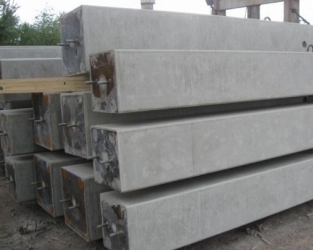
Reinforced concrete columns are one of the most popular types of reinforced concrete products. They are vertically located building structures and are used as load-bearing elements of the frame: beams, crossbars, girders, etc.
Such products are designed for a constantly high compressive load, they are also able to work in bending, withstanding high wind loads. Our company manufactures reinforced concrete columns of any size in compliance with high quality standards.
Features and Key Features
During production, either standard dimensions are used, if the building is being built according to a standard project, or individual dimensions in accordance with the drawings. Most often, these structural elements are made for the implementation of a specific individual project, in which case they correspond to all the personal wishes of the customer and the provided working documentation.
The cost of a reinforced concrete column is determined by several key factors:
- The class of concrete used in terms of strength, frost resistance and water resistance. Reinforced concrete columns of industrial buildings are subject to special strength requirements, respectively, they will cost more.
- Concrete column size. The length can be from 5.7 to 17 meters, as a rule, the height is equal to the height of two floors of the building.
- Type of reinforcing cage, the presence of embedded parts. Products for industrial buildings are equipped with high-strength reinforcement to increase resistance to compressive and bending loads. For them, prestressed or non-stressed reinforcement is used.
- Presence of standard metal equipment. Also, the final cost depends on the time allotted for the manufacture of reinforced concrete products.
The key characteristic of reinforced concrete columns is load bearing capacity. The lower it is located in the building structure, the higher its load-bearing characteristics should be, the highest requirements are placed on products installed in the technical underground and on the lower floors of the building.
Types and materials for manufacturing
Reinforced concrete columns of one-story industrial and residential buildings are made of heavy grades of concrete M300-M600. Steel reinforcement provides the product with durability and high resistance to all destructive influences. The cross section can be round, square or rectangular, it depends on the loads and on the features of the structure.
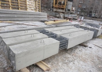
For multi-storey residential buildings, products with cantilevered protrusions are used, which are used as a support for floor beams and become one of the main elements of the frame, since they have to withstand the main load.
The columns of the extreme and middle rows are also distinguished, depending on the location in the frame system of the building. Their connection with other elements of the frame is carried out by welding embedded elements, followed by concreting the joints. For the installation of reinforced concrete columns of industrial buildings, special column foundations of glass or monolithic type are used.
Our company offers to place an order for any number of reinforced concrete columns at competitive prices. Products are manufactured in accordance with state standards, it meets all quality requirements. Production of products of the non-standard size according to individual drawings is offered.