Technologies for the construction of buildings from monolithic reinforced concrete. Monolithic construction of warehouses and industrial buildings
Industrial facilities are a successful symbiosis strength characteristics reinforced concrete structures and the latest developments in the field of thermal insulation and cladding materials, which allow us to implement any bold projects that meet the highest safety requirements and complete it in a short time. One of promising directions of the modern construction market, one can undeniably call monolithic construction
The main load-bearing elements are erected from the monolith, and the external elements (walls, roof) are made of cassette sandwich panels. Monolithic construction involves the construction of inseparable reinforced concrete frames, which are located along the entire height from the foundation to the ceiling of the last floor.
formwork in monolithic construction
In the construction of monolithic frame structures, formwork is of particular importance. . The use of modern formwork systems made it possible to improve the reliability and speed of the construction itself. The result of using the formwork is a flat concrete surface that does not require additional finishing.
Formwork-based monolithic construction technology has become especially widespread in the implementation of projects that combine both residential and industrial facilities, due to the versatility of structures and a wide variety of modular grid for columns.

monolithic construction
Analysis of price costs shows that today there is no worthy alternative to monolithic construction. And despite the use of expensive raw materials and large industrial capacities for the manufacture of monolithic formwork, the production and sale of formwork systems is in high demand on the market.
For the production of building monolithic formwork, steel, wood and aluminum plywood are used. And it is the material that is the decisive factor in the final pricing.
Depending on the conditions of use, monolithic formwork can be classified according to its components:
- panel board,
- beam-transom
- small-panel formwork
The main stages of monolithic construction
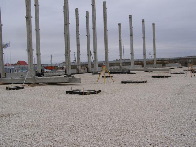
Let us consider the process of monolithic construction of an industrial building on the basis of the project "Industrial and warehouse complex" in the settlement. Lagovskoe, Moscow region. The project was implemented by the company GK "SPETSSTROY".
Soil development . Development works can take place in several stages and include changes in the relief, arrangement of trenches for engineering networks and foundations, soil stabilization, site leveling. Proper selection of road construction equipment is the key to cost optimization and time planning

excavation
Foundation preparation . The main task is to bring bearing capacity soil to design indicators and ensuring high-quality contact of the foundation with the base. For device pile foundation with a monolithic grillage, a sand cushion is used. After the installation of the piles, the formwork, the reinforcing cage are arranged and the concrete is poured.

ground preparation
Installation of monolithic grillages . For the installation of grillages, a drainage cushion made of crushed stone or slag is organized.
arrangement of grillages
Installation of prefabricated reinforced concrete structures . Installation is carried out floor by floor and tiered. The joints are sealed with concrete. Each subsequent tier is mounted only after fixing all the elements and achieving at least 70% of the strength of the mixture at the joints.

assembly of prefabricated structures
Erection and installation of monolithic structures . As the concrete hardens, the formwork components are disassembled and transferred to the next floor. Most often, panel formwork is used (from separate forms). During installation, prefabricated elements are most often used: flights of stairs, elevator shafts
The device of a monolithic elevator shaft

Installation of metal trusses
![]()
The construction of walls in parallel with the arrangement of the frame
The walls that are being built monolithic technology, suggest the almost complete absence of seams, as a result, there are no problems with sealing joints. The erection of monolithic walls and ceilings of small thickness significantly reduces the load on the foundation.
Another important advantage of monolithic construction is the high coefficient of sound insulation of the premises. Even in brick houses wall partitions imply the presence of voids, which contributes to the propagation of sound; in monolithic structures, this drawback has been eliminated.
A special characteristic of monolithic structures is rigidity and strength. Monolithic buildings in this regard have firmly taken a leading position. Uniform shrinkage of the building and redistribution of loads prevents the formation of cracks. That is why reinforced concrete is used in industrial construction.
Some difficulties may arise during the cold season, when it is necessary to slow down the process of concrete hardening. In order to prevent the deterioration of the quality of concrete, it is heated using special additives or inert materials - crushed stone and sand.

concrete heating cable
The technology of concreting with the help of electricity is also often used, when the concrete poured into the formwork is heated by an electric cable.
Leningrad Terminal MLP - as an object of monolithic construction
In 2004, the MLP company acquired the first site in the Moscow region and announced a bold development strategy - to build 1.5 million square meters. m of warehouse real estate in Russia, Ukraine and regions.
Today it is one of the largest logistics projects in Russia, which is built in accordance with all modern international standards. The terminal is aimed at serious tenants, transnational manufacturers of consumer goods, leading distributors. "MLP - Leningrad Terminal" occupies an area of 42 hectares along the Leningrad highway and includes 197.35 thousand square meters. m warehouse class A. 3
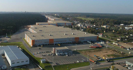
Leningrad Terminal MLP
The height of the warehouse complex is 15.5 m (working height - 12.5 m) provides rack storage on 6 tiers Floors are designed for a load of up to 6 tons, which allows you to withstand any equipment for transporting and lifting goods. A special climate control zone has been developed for warehousing products and goods with special storage conditions. The terminal uses an air heating system and air conditioners from Lennox (France), a modern fire extinguishing system. The electricity supply system at the MLP is provided by 8 autonomous diesel generator transformer stations.
Main function load-bearing structures warehouse terminal is made of monolithic 15-meter reinforced concrete columns installed with a step of 12x24 m (as practice has shown, this technology is cheaper than the construction of metal columns, which require additional fire-fighting treatment).
Warehouse walls lined with 120 mm sandwich panels Russian production, using Finnish insulation. For the arrangement of the roofing, the well-proven Alkorplan (Belgium) membrane roofing made of plasticized PVC was used. This membrane provides 300% stretch and correct operation will last over 50 years.
floors- for a warehouse, this is one of the most important details, since heavy loading equipment moves at high speed on the flooring. Voids in the concrete base slab will sooner or later lead to destruction floor covering and equipment failure. Repair of floors will lead to the need to dismantle the racks and, as a result, to the closure of the warehouse. And repairing a forklift is a troublesome task, given that one wheel of a reach truck can cost up to $1,000.
![]()
Warehouse floors
When constructing the base, all the nuances and mistakes of the predecessors were taken into account. Thickness concrete slab with double reinforcement was 200 mm. The developer applied the vacuum laying technology patented by the Swedish company Tremix, in which the concrete is placed along the guides, and then it is subjected to vacuum dehydration and vibrocompaction.
Mirror surface concrete base performed by grouting with twin-rotor helicopter machines. In order to achieve extra high wear resistance and eliminate dusting, additives were used in the concrete of a strengthening liquid membrane-forming agent - the "top" composition from Durocem (Italy).
This stage of work caused particular difficulties, since the process of laying the floor coincided with the onset of winter frosts. To maintain the quality of concrete and continue work on interior decoration, after the temperature rise in the street, the heating of the warehouse with heat guns "Master" was started. To warm up the entire cubic capacity of concrete, it was necessary to burn 6 tons of kerosene per day!
Page 2 of 13
To monolithic include massive stone from rubble masonry, rubble concrete, concrete (without cladding and cladding) and reinforced concrete supports.
stone supports
Stone supports have been known since ancient times. For example, under the emperor Trajan in 104 AD. e. a bridge across the Danube was built with a total length of about 1 km with spans of 52 m. span structures wooden arched bridges. The foundations of the supports were built on the rock, the thickness of the intermediate stone support was 18 m - about a third of the span. In the Middle Ages, arched bridges with massive stone pillars were often built in European cities. In the first quarter of the XX century. in Russia, many bridges of the beam split system with rubble masonry supports that have survived to this day have been built.
Granite, limestone, sandstone were used as materials for stone supports. We also used natural rubble and cobblestone with a preliminary chipping of the edges, as well as material obtained by the development of layered stone rocks with a strength of at least 40 MPa. Used for supports and clay bricks.
stone supports very durable, they have enormous reserves of strength. However, at present, due to the high material consumption, significant labor intensity of work and the impossibility of complete mechanization of work, they are practically not being built.
Rubble concrete supports
In the 19th century rubble-concrete supports are widely used. In supports of this type, stone (but) is not the main material, but serves, along with the concrete mixture, as a component of concrete masonry and makes up about 40% of the volume of the support. (If the stones are not more than 20%, they are called "raisins".) Consumption of materials in rubble concrete supports: buta - 0.6 m 3 per 1 m 3 of masonry, concrete mix - 0.7 m 3 per 1 m 3 of masonry. The consumption of cement is greater than in stone supports - 200-250 kg per 1 m 3 of masonry.
Work order:
- construct the formwork of the support body and lay a layer of concrete mixture with a thickness of 25-30 cm;
- individual stones are laid out on a freshly laid layer, which are not completely sunk into the concrete mixture;
- again spread a layer of concrete mixture with a thickness of at least 20 cm and again lay out individual stones, not completely sink them into the concrete mixture, etc.
The size of the stone should not be more than 1/3 of the thickness of the support; the stone must be at least 10 cm from the edge of the support.
The contact between adjacent layers along the height is sufficiently reliably ensured by stones protruding from the lower layer.
Compared to stone rubble concrete supports more technologically advanced, less labor-intensive, the pace of their construction is higher. However, formwork is required for their construction.
Concrete and reinforced concrete supports
The scope of construction in our country in the 30s of the XX century. demanded an acceleration in the construction of bridges. Adhering to the traditional shapes and sizes of massive stone pillars, bridge builders began to build concrete pillars. This made it possible to mechanize work and speed up construction.
The supports were constructed entirely in granite stone cladding or partially clad (fore part).
According to SNiP 2.05.03-84*, the surfaces of intermediate concrete supports of bridges located in areas with an average monthly air temperature of the coldest month below -20 ° C, and on rivers that open at average daily negative temperatures are subject to facing. In other conditions, it is not necessary to clad concrete supports, unless it is required for architectural reasons.
Main purpose cladding- protect the masonry from the abrasive effects of ice drift and water-sand mixtures. It ensures the durability of the structure and gives the support an architecturally attractive appearance. appearance.
The height of the support is lined within the variable level of ice drift. It can be performed both along the contour and partially - in the bow.
Rice. 3.2 - Facing the support body: a- massive; b- hinged; 1 - facing stone spoon; 2 - the same, tychkovy; 3 - concrete core of the support body; 4 - "well"; 5 - facing plate; 6 - a loop released from concrete; 7 - anchor; 8 - knitting wire; 9 - gap filled with concrete mix; 10 - brace
On rivers with ice drift massive cladding from natural and artificial (concrete) stones. The material for it is natural rocks with a strength of at least 60 MPa (with a powerful ice drift - 100 MPa) or concrete of class B 45 in strength and frost resistance grade F500. The stones are laid out in order along the outer surface of the support body and at the same time the concrete mixture is laid in the support core (Fig. 3.2, a). The front surface of the stones is processed into a rough joke (with irregularities of the front surface of the stone of 20-50 mm), according to the rules of semi-clean (irregularities up to 5 mm) or clean tees (irregularities up to 2 mm). Along the perimeter of the facade of each stone, you can cut a strip up to 50 mm wide (“tape”), the rest of the facade part of the stone is called a “fur coat”.
Facing is arranged from the corner (or curvilinear) parts of the support after geodetic marking of the position of the support body on the foundation. A row of stones is laid out dry along the perimeter of the support, with each stone placed on two wooden wedges that fix the thickness of the seam (it ensures the solidity of the masonry), which should be 10-15 mm. After reconciling the position of the stones, the seams are caulked with tow. The core of the support body is filled after each row is laid, and for better mating of the layers, the upper surface of the concrete should not reach the top of the stones. During concreting, it is ensured that when vibrating the concrete mixture, the stones do not move out of the support, for which the concrete does not reach the tail parts of the stones. The resulting "wells" between the inner surfaces of the stones and the core are poured with a cement-sand mortar. Large facing stones can be immediately laid on a layer of thick cement-sand mortar (if there are wooden wedges under the stone).
After the masonry of the support is completed, the caulk is removed from the seams, then the seams are washed and jointed, i.e. they are filled with a thick-plastic mortar, giving the outer surface of the seam a concave shape with a depth of 6-10 mm.
Lack of masonry - a large number of working seams arranged through distances equal to the height of the row.
Massive cladding made of natural rocks is extremely labor-intensive. In modern conditions, supports, as a rule, are constructed in the form of prefabricated monolithic structures lined with concrete blocks.
With high requirements for the appearance of the supports in conditions of moderate ice drifts, hinged cladding from slabs 15-20 cm thick, made of natural stone or reinforced concrete (Fig. 3.2, b). The support in this case is concreted in the formwork, there are no working seams characteristic of supports with massive cladding. After dismantling the formwork, facing plates are installed in order. Each of them is fixed to the concrete support with special anchor brackets connecting the slabs with mild reinforcing steel loops (they are embedded in the support during the concreting process).
Facing plates are installed on the mortar, vertical seams are caulked from the outside and poured with a liquid mortar. The space between the slab and the core of the support (150-200 mm) is filled with concrete mixture after the installation and fixing of the slabs. After completion of work, the seams are embroidered.
If there is no need for lining the supports, the procedure may be as follows:
- Marking the position of the axes and contour outlines of the support body on the foundation;
- Assembling the formwork of the above-foundation part of the support and, for a reinforced concrete support, installation of the reinforcing cage;
- Preparation, delivery and laying of the concrete mixture into the formwork;
- Concrete curing: implementation of a set of measures to ensure its normal hardening;
- Dismantling of formwork and finishing of support surfaces. The works that make up the process of constructing the above-foundation part of the support are briefly described below.
Formwork assignment.
Most of the volume monolithic concrete and reinforced concrete are used for the construction of zero-cycle structures and only 20 ... 25% is spent on the above-ground parts of buildings and structures. The greatest efficiency of monolithic structures is manifested in the reconstruction industrial buildings and structures, as well as in the construction of housing and communal construction. The use of monolithic concrete makes it possible to reduce the consumption of steel by 7...20%, concrete up to 12%. But at the same time, energy costs increase, especially in winter time, and increased labor costs at the construction site. So, the labor costs at the construction site during the construction of buildings from monolithic reinforced concrete 1.65 times higher than in the construction of large-panel buildings. It is clear that the bulk of the work in the construction of buildings from monolithic concrete falls on the construction site. But the increase in concrete consumption by 17 ... 19% compared with large-panel housing construction is explained by the insufficient use of lightweight concrete, modern slab insulation and the use of lower grades of cement.
The construction of buildings from monolithic reinforced concrete allows optimizing their design solutions, moving to continuous spatial systems, taking into account the joint work of elements and thereby reducing their cross section. In monolithic structures, the problem of joints is easier to solve, their thermal engineering and insulating properties are increased, and operating costs are reduced.
The complex process of erection of monolithic structures includes:
Procurement processes for the manufacture of formwork, reinforcing cages, reinforcement-formwork blocks, preparation of ready-mixed concrete. These are mainly factory production processes;
Construction processes - installation of formwork and reinforcement, transportation and placement of concrete mix, curing of concrete, dismantling of formwork.
Formwork system - a concept that includes formwork and elements that ensure its rigidity and stability, fasteners, supporting structures, scaffolding.
Types and purpose of individual formwork elements and formwork systems:
Formwork - a form for monolithic structures;
Shield - a formwork formwork element, consisting of a deck and a frame;
Deck - an element of the shield that forms its forming working surface;
Shuttering panel - a forming flat formwork element, consisting of several adjacent panels interconnected by means of connecting nodes and elements and designed to formwork the entire specific plane;
The formwork block is a spatial element, closed along the perimeter, made entirely and consisting of flat and corner panels or shields.
The formwork material is steel, aluminum alloys, moisture-resistant plywood and wood boards, fiberglass, polypropylene with high-density fillers. Formwork supporting elements are usually made of steel and aluminum alloys, which allows them to achieve high turnover.
Combined formwork designs are the most efficient. They allow the greatest use of the specific characteristics of materials. When using plywood and plastic, formwork turnover reaches 50 times or more, while the quality of the coating increases significantly due to the low adhesion of the material to concrete. Sheets with a thickness of 2 ... 6 mm are used in steel formwork, which makes such formwork quite heavy. formwork from wooden materials protected with synthetic coatings. Films are applied to the deck by hot pressing, using bakelite liquid resins for wood impregnation, epoxy-phenol varnishes, and glass cloth impregnated with phenol-formaldehyde. At present, the most widespread is moisture-resistant plywood, produced with a thickness of 18 ... 22 mm. For the cover layer, fiberglass, laminated plastics, vinyl plastics are used.
The main types of formwork.
The formwork is classified according to its functional purpose, depending on the type of concrete structures:
For vertical surfaces, including walls;
For horizontal and inclined surfaces, including ceilings;
For simultaneous concreting of walls and ceilings;
For concreting rooms and individual apartments;
For curved surfaces (mainly pneumatic formwork is used).
At concrete work ah, the following auxiliary elements of formwork systems are used.
Hanging scaffolds - special scaffolds hung on the walls from the side of the facades using brackets fixed in the holes left during the concreting of the walls.
Roll-out scaffolds - scaffolds designed to roll out tunnel formwork or slab formwork during their dismantling.
Opening formers - a special formwork designed to form window, door and other openings in monolithic structures.
The main directions for improving the manufacturability of monolithic structures and reducing labor costs for the implementation of a complex of concrete works:
Switching to highly mobile and cast concrete mixtures with chemical additives, which reduces labor costs for transporting, laying and compacting concrete to a minimum - reducing manual labor from 35 to 8%, and simultaneously with an increase in the intensity of concreting, the relative cost of laying the concrete mixture is significantly reduced;
The use of fully prepared reinforcement cages, the transition from welded joints to mechanical joints - a decrease in labor intensity by 1.5 ... 2 times;
The use of inventory, quick-release formwork of modular systems with a special polymer anti-adhesion coating, which eliminates the cost of cleaning and lubricating the deck;
The use of formwork systems for continuous concreting, the use of fixed formwork, reducing or eliminating labor costs for their dismantling.
If we take the total labor intensity of erection of monolithic reinforced concrete structures as 100%, then the labor costs for the execution of formwork are approximately 45...65%, reinforcing - 15...25% and concrete - 20...30%.
Article prepared and presented digitally by "SBH COTPAHC"
The composition of the complex process.
The complex process of erection of monolithic reinforced concrete structures consists of technologically related and sequentially performed simple processes:
Formwork and scaffolding installations;
Installation of fittings;
Installation of embedded parts;
Concrete laying and compaction;
Care of concrete in summer and intensification of its hardening in winter;
stripping;
Often there is an installation of prefabricated structures.
The time required for concrete to gain stripping strength is included in the general technological cycle.
The composition of simple processes, their labor intensity and the sequence of execution depend on the type and specifics of the erected monolithic structures, the mechanisms used and the types of formwork, technological and local features of the work.
Each simple process is performed by specialized units, which are combined into an integrated team. The structure is divided in height into tiers, in plan - into grips, which is necessary for organizing the flow of work.
Breakdown into tiers - high-altitude cutting, due to the admissibility of breaks in concreting and the possibility of the formation of temperature and working joints. So, one-story building usually divided into two tiers: the first - foundations, the second - all other frame structures. AT high-rise building for a tier, they take the entire floor with ceilings. A tier height of more than 4 m is undesirable, since with a high height and intensive concreting, the lateral pressure on the formwork from the laid concrete mixture increases.
Breakdown into grips - horizontal cutting, which involves:
Equivalent in terms of labor intensity of each simple process, the permissible deviation is not more than 25%;
The minimum size of the grip (working area) - the work of the link during one shift;
The size of the capture, linked to the size of the block, concreted without interruption or with the device of working joints;
The number of captures on the object, equal to or a multiple of the number of threads.
For a clear organization of the implementation of the complex process of concrete work in-line, it is necessary:
Determine the complexity of each process;
Divide the object into tiers and grips, similar in terms of labor capacity for each process, sufficient for the link to work during the shift;
Set the rhythm of the flow and the overall optimal period of work;
Define and select optimal equipment for submission to workplace formwork, reinforcement and concrete mix;
Determine the required number of workers, based on the complexity of individual processes, the accepted rhythm of the flow, and complete the units and teams;
Draw up a calendar (shift) schedule of the complex process.
Options with pooling of flows are possible. So, often in one stream formwork is installed and reinforcement is immediately mounted into it. Separation is also possible, when the concreting of walls and ceilings and related processes are separated into independent flows.
Concreting is the leading process in the complex process of erecting monolithic structures. This process consists of related operations for transportation, supply to the workplace, acceptance and compaction of the concrete mix. Concreting affects the timing of formwork and reinforcement work, which are closely technologically dependent on it. Therefore, to ensure a rhythmic flow with different labor intensity of heterogeneous processes, the same duration of work (the duration of concreting) is taken with a different numerical composition of links for each of them.
It is desirable to develop several options technology of work and accept the option with optimal technical and economic indicators. When designing the production of works, it should, if possible, provide for the implementation of processes for concreting and installation of structures in the first shift.
The basic principle of work design: how many processes, how many grips (working areas, concreting blocks). In table. 21.1 shows a schedule for the production of work on the construction of a floor of a multi-storey residential one-section building with monolithic walls and prefabricated ceilings. When designing the work, it is planned to combine all construction processes into four complex processes, split the floor-grip into 4 work areas with approximately equal amounts of work (within 25% of labor intensity), reduce the need for formwork by 4 times - to the volume of concreting in one work area .
Mechanization of concrete works.
Transportation of concrete mix. The concrete mixture is delivered to the consumer, i.e. to the concrete work area, by concrete trucks or concrete mixers. Concrete trucks - open dump trucks with a body volume of 3 ... 5 m3 are usually used when a concrete plant is located within 10 minutes of travel to the construction site. Concrete mixer trucks are a concrete mixer with a volume of 5 ... 8 m3, installed on vehicles such as MAZ, KamAZ (for smaller volumes) and Renault, Mercedes (for large volumes). Domestic concrete mixers are produced with two modes of operation: forced mixing of the concrete mixture at the command of the driver from the cab and with mixing of the concrete mixture only when the car is moving. The disadvantage of mixers of the second type is the limited scope of their application only in the construction of facilities, where concreting is carried out strictly according to the schedule, in the event of an unforeseen waiting, unloading becomes much more complicated.
Laying concrete mix. Concrete mixture is fed into the structure in various ways: through the tray, hoisting mechanisms, concrete pumps. The first two methods are used when laying up to 50 m3 of concrete per shift, the third - for any volume, but it is economically feasible to use it when laying at least 45 m3 of concrete mix per shift. Concrete mixture is fed along the tray if it is possible to install a concrete mixer above the level of the structure to be concreted, for example, when pouring a foundation slab and the possibility of driving a car to the bottom of the pit. The trays are made of moisture-resistant plywood or metal sheets up to 6 m long. To supply the concrete mix in tubs or bunkers, the existing lifting mechanisms used for other loading and unloading operations are used. These are mainly mobile and tower cranes, sometimes they use attachment cranes. The buckets have a volume of 0.3 ... 1 m3 and, for the convenience of supplying the concrete mixture, are made in the form of a "glass", on which a vibrator is installed for its complete emptying.
Concrete pumps are the most widely used when laying concrete mix. With a laying volume of up to 80 m3 of concrete per shift, domestic or imported concrete pumps based on KamAZ, MAZ, Mercedes vehicles are used. Truck-mounted concrete pumps are equipped with a loading hopper, a pump and a distributing boom. The concrete mixture is fed in vertical (up to 80 m) and horizontal (up to 360 m) directions. In the construction of facilities with a need for more than 60 m3 of concrete per shift, as well as buildings with an increased number of storeys (more than 20 floors), stationary concrete pumps are used, complete with distributing concrete pavers. Concrete pavers with an outreach of up to 60 m are installed on the assembled building structures or auxiliary supports. The hopper of the concrete pump is connected to the concrete paver by means of a vertical pipeline through which the mixture flows. From one parking place of the concrete paver, concrete is laid on several tiers. The concrete paver, whose mass is 1...6 tons, is moved to the next parking lot by a mounting crane installed at the facility, the concrete conduit is lengthened and the concrete mixture is fed to the newly erected tiers of the building. To compact the concrete mixture, if it is required by the technology of work, vibrators for various purposes are used: for vertical structures - deep vibrators, for horizontal structures - vibrating screeds.
Formwork of the company "Meva".
Meva formwork systems. The German company "Meva" produces several types of formwork, common in solution, but differing in some design features. Formwork system "Meva" is designed for formwork of any horizontal and vertical building structures, both for the smallest and large structures under construction. This system features several distinctive and original design elements that have earned it the recognition it deserves. The shuttering lock provides a quick and safe connection of two shuttering panels in horizontal and vertical structures at any point of the structural frame. Closed profiles of frames and stiffeners create formwork connections that successfully withstand torsion loads, facilitate the processes of joining elements, and increase construction safety. The elements of functional fastening of opposing formwork panels to each other include screw ties with special threads, which drastically reduces labor costs and facilitates all connections.
Specificity of Meva formwork panels: all panels frames are made of steel, aluminum or mixed frame, they are made of one-piece hollow profile with curved corrugation and reliable edge protection of deck elements. Patented interlocks of the formwork panels are suitable for all Meva systems and are power, which allows them to be used anywhere in the frame. When applying a lock, two shields are pulled together (they have a bottom leveled) and the lower parts of the profiles, and the elements are closed with a hammer blow by pulling them together in places of a special bevel. The lock weighs 2.8 kg and can be inserted and secured with one hand. The wedge in the lock is non-removable, which constantly ensures the completeness of the lock. The advantage of this constructive formwork solution is the rigidity of not only the panels, but also the entire formwork panel. The formwork design makes it possible to install panels not only vertically, but also horizontally, which reduces their range, while the rigidity and strength of the connection of panels does not decrease.
a - general form wall formwork assembly, b - column formwork, 1 - formwork shield, 2 - stiffeners, 3 - leveling and clamping tires, 4 - bar-insert; 5 - elongated lock, 6 - junction of two board decks, 7 - brace, 8 - coupling element, 9 - plywood deck, 10 - formwork shield contour frame, 11 - lock.
Small-panel formwork "Rasto" of the company "Thyssen". The German company Thyssen widely implements its formwork systems. In particular, it has developed formwork sets that complement each other, namely, Rasto small-panel formwork, Manto large-panel formwork and Sompakt slab formwork.
Formwork "Rasto" is designed for manual installation of panels. It is easy to use, durable, withstands the pressure of the concrete mixture up to 60 kN/m2, is versatile, and can be used in various areas of construction.
The main element is a shield with a height of 270 cm; for tall structures, additional shields with a height of 150 cm, a width of 45 to 90 cm with a gradation of 5 cm are applicable. Shields are easy to combine vertically and horizontally, adjustment is carried out along the length with a module of 5 cm, shield extension is possible both when the horizontal seams coincide, and when they are displaced.
The formwork panels of the Rasto system are made of hot-dip galvanized steel, the formwork elements have high endurance and strength. The formwork frame is made of a metal profile 12 cm high, along the perimeter it has a protrusion 14 mm high, which protects the ends of the deck of the same thickness from all sides. The frame is equipped with longitudinal ribs every 30 cm, depending on the width of the shields, it has 1 ... 2 transverse ribs. The presence of corner fasteners in certain places ensures high rigidity and stability of the panels, and the use of hollow profiles for the frame significantly reduces their weight. The 2.7 x 0.75 m shield weighs only 60 kg and can be moved and assembled by hand. Article source: www.sbh.ru
To connect the shields, universal locks (rasto-squeezes) are used. An eccentric lock (combi-squeeze) 40 cm long connects two adjacent elements in one working turn of the lamb butt-to-butt, counteracting tension, possible vibration and pressure of the concrete mixture. The clamp not only aligns and ensures the alignment of the shields, the rigidity of the joint allows for crane lifting of the shields with total area up to 40 m2. When it is necessary to connect “standing” and “lying” boards or to install an insert up to 15 cm wide between the boards, elongated locks (sliding combi-clamps) 55 cm long are used. Special corner sliding clamps with a backlash of up to 6 cm have also been developed. Rasto" allow one movement of the strap to hook the clamping pads, providing a tight connection of adjacent shields. The dismantling of these eccentric wedge locks is simple and does not require extra effort. The lock connections are located during installation, two locks per two abutting shields and allow easy dismantling without compromising stability common system formwork.
Small-panel formwork by Dally. Dally formwork consists of modular elements, which makes it possible to complete the formwork panel with vertical and horizontal panels. The main advantage of the formwork is that from a minimum number of elements and original fasteners, it is possible to manually assemble the formwork of a wide variety of horizontal and vertical structures. Boards are produced in three sizes in height - 264, 132 and 88 cm and 10 sizes in width - from 75 to 20 cm with a gradation of 5 cm. Standard boards measuring 264 x 75 cm have a mass of 60 kg, manual installation of formwork elements is allowed. At the ends of each shield, two welded hex nuts are provided for a strong pin connection of two adjacent shields (Fig. 22.3).
The working surface of the formwork is a 5-layer wooden board 21 mm thick with double-sided reinforced cladding, which allows using each formwork element at least 350 times with regular cleaning and lubrication. The frame elements of the shields are made of sheet steel with overlays and scarves, which makes the frame quite rigid, but this solution can significantly reduce the weight of the shield. Each shield is attached with just two tie rods,
Small-panel wall formwork by Dally:
a - serial elements; b - the junction of two shields; 1 - stiffening elements of shields; 2 - groove for mounting opposing shields; 3 - leveling tire
Among the domestic formworks, the unified formwork developed by the TsNIIOMTP Institute is the most common. The wall formwork consists of boards one floor high with a modular width of 300 to 1800 mm, as well as additional boards - end and corner. The shield consists of a metal deck, horizontal beams and vertical trusses. Screw jacks are provided at the bottom of the shields. In the formwork, it is possible to concrete walls with a thickness of 12, 16 and 20 cm at a height of up to 3 m and ceilings with a thickness of 10 ... 22 cm.
Monolithic overlap suit after the erection of walls and the set of the necessary initial strength by them. The slab formwork is mounted on telescopic props, reinforcing meshes are laid in two levels, and concreting is carried out.
Elements of collapsible formwork:
1 - wooden frames of the columns; 2 - column formwork; 3, 4 - formwork panels; 5 - shield of the bottom of the beams; 6 - wooden formwork beams; 7 - side panels of the beam formwork; 8 - supporting telescopic racks on tripods.
Organization of work and technological features various formworks and formwork systems are discussed in the monolithic housing construction section. The construction of buildings from concrete and reinforced concrete monolithic structures is specific and differs from the construction of buildings and structures made of brick, precast concrete, wooden and metal structures. The presence of the so-called "wet processes", the need for curing concrete structures to gain strength determine the specifics of their production.
Attention is paid to the breakdown of the concreting zone into sections, tiers, the recruitment of brigades and units, the organization of in-line production of a complex of concrete works.
The specifics of the use of a wide variety of formworks used for concrete work, which are divided into four main groups: collapsible-adjustable, horizontally and vertically movable, and the so-called special formwork, which include pneumatic, fixed and heating, are considered.
1. BUILDING AND STRUCTURAL FEATURES OF CONSTRUCTION OF BUILDINGS FROM MONOLITHIC CONCRETE.
1.1 Purpose of formwork.
Most of the volume of monolithic concrete and reinforced concrete is used for the construction of zero-cycle structures, and only 20 ... 25% is spent on the above-ground parts of buildings and structures. The greatest efficiency of monolithic structures is manifested in the reconstruction of industrial buildings and structures, as well as in the construction of housing and communal construction facilities. The use of monolithic concrete makes it possible to reduce the consumption of steel by 7...20%, concrete up to 12%. But at the same time, energy costs increase, especially in winter, and labor costs at the construction site increase. Thus, labor costs at the construction site during the construction of buildings from monolithic reinforced concrete are 1.65 times higher than during the construction of large-panel buildings. It is clear that the bulk of the work in the construction of buildings from monolithic concrete falls on the construction site. But the increase in concrete consumption by 17 ... 19% compared with large-panel housing construction is explained by the insufficient use of lightweight concrete, modern slab insulation and the use of lower grades of cement.
The construction of buildings from monolithic reinforced concrete allows optimizing their design solutions, moving to continuous spatial systems, taking into account the joint work of elements and thereby reducing their cross section. In monolithic structures, the problem of joints is easier to solve, their thermal engineering and insulating properties are increased, and operating costs are reduced.
The complex process of erection of monolithic structures includes:
Procurement processes for the manufacture of formwork, reinforcing cages, reinforcement-formwork blocks, preparation of ready-mixed concrete. These are mainly factory production processes;
Construction processes - installation of formwork and reinforcement, transportation and placement of concrete mix, curing of concrete, dismantling of formwork.
Formwork system- a concept that includes formwork and elements that ensure its rigidity and stability, fasteners, supporting structures, scaffolding.
Types and purpose of individual formwork elements and formwork systems:
formwork- form for monolithic structures;
shield- forming formwork element, consisting of a deck and a frame;
deck- an element of the shield, forming its forming working surface;
formwork panel- shaping flat formwork element, consisting of several adjacent panels interconnected by means of connecting nodes and elements and intended for formworking the entire specific plane;formwork block- a spatial element closed along the perimeter, made entirely and consisting of flat and corner panels or shields.
The formwork material is steel, aluminum alloys, moisture-resistant plywood and wood boards, fiberglass, polypropylene with high-density fillers. Formwork supporting elements are usually made of steel and aluminum alloys, which allows them to achieve high turnover.
Combined formwork designs are the most efficient. They allow the greatest use of the specific characteristics of materials. When using plywood and plastic, formwork turnover reaches 50 times or more, while the quality of the coating increases significantly due to the low adhesion of the material to concrete. Sheets with a thickness of 2 ... 6 mm are used in steel formwork, which makes such formwork quite heavy. Formwork made of wooden materials is protected with synthetic coatings. Films are applied to the deck by hot pressing, using bakelite liquid resins for wood impregnation, epoxy-phenol varnishes, and glass cloth impregnated with phenol-formaldehyde. At present, the most widespread is moisture-resistant plywood, produced with a thickness of 18 ... 22 mm. For the cover layer, fiberglass, laminated plastics, vinyl plastics are used.
Plastic formworks are used, especially those reinforced with fiberglass. They have high static load strength and are chemically compatible with concrete. Formworks made of polymeric materials are characterized by low weight, shape stability and resistance to corrosion. Possible damage can be easily repaired by applying a new coating. The disadvantage of plastic formwork is that their bearing capacity is sharply reduced during heat treatment with an increase in temperature up to 60°C.
Combined formworks have appeared, when sheet polypropylene is applied to the metal deck. The use of composites with conductive filler makes it possible to obtain heating coatings with controlled modes of thermal action on concrete.
The article was prepared and submitted digitally by the company
1.2 The main types of formwork.
The formwork is classified according to its functional purpose, depending on the type of concrete structures:
For vertical surfaces, including walls;
For horizontal and inclined surfaces, including ceilings;
For simultaneous concreting of walls and ceilings;
For concreting rooms and individual apartments;
For curved surfaces (mainly pneumatic formwork is used).
For concreting walls, formwork of the following types is used: small-panel, large-panel, block-form, block and sliding.
For concreting the slabs, a small-panel formwork with supporting elements and a large-panel formwork are used, in which the formwork surfaces form a single formwork block, completely rearranged by a crane.
For simultaneous concreting of walls and ceilings or parts of a building, volumetric-adjustable formwork is used. For the same purposes, horizontally movable formwork, including rolling formwork, is used, which can be used for concreting vertical, horizontal and inclined surfaces.
Collapsible small-panel formwork consists of a set of small elements with an area of up to 3 m2 and a weight of up to 50 kg, which allows you to install and disassemble them manually. Formwork elements can be assembled large panels and blocks mounted and dismantled by a crane without dismantling into constituent elements. The formwork is unified, applicable for a wide variety of monolithic structures with constant, variable and repeating dimensions. It is most advisable to use formwork for concreting non-standardized structures of small volume.
Large-panel formwork consists of large-sized shields and connection elements. Formwork boards perceive all technological loads without installing additional load-bearing and supporting elements. Formwork is used for concreting extended walls, ceilings and tunnels. The size of the shields is equal to the size of the structure to be concreted: for walls - the width and height of the room, for the floor - the width and length of this floor. In the case of concreting floors of a large area, when it is not possible to lay and compact the concrete of the structure during one shift, the floor is divided into maps. The dimensions of the card are set by the technological regulations, a metal mesh 2 ... 4 mm thick with cells 10 x 10 mm is installed at their borders to ensure sufficient adhesion to subsequent cards. Large-panel formwork is recommended for buildings with monolithic walls and partitions, prefabricated ceilings. Collapsible large-panel formwork is also used for concreting structures of variable cross-section (silos, chimneys, cooling towers).block formwork- this is a volume-adjustable formwork designed for the construction of three or four walls simultaneously along the contour of a building cell without an overlapping device. The formwork is assembled from separate blocks with gaps equal to the thickness of the walls being erected.
For buildings with monolithic external and internal load-bearing walls and prefabricated ceilings, a combined variant is recommended: for the external surfaces of the walls - large-panel formwork, and for internal surfaces and walls - block, vertically movable and extractable formwork.
Block Forms are spatial closed blocks: one-piece and rigid, made on a cone, detachable or sliding (reconfigurable). Block molds are used for concreting closed structures of a relatively small volume, not only for vertical, but also for horizontal surfaces. In addition, they are used for volumetric elements of walls, elevator shafts, free-standing foundations, columns, etc.
Variable formwork consists of U-shaped sections and is a horizontally extractable large-sized block designed for simultaneous concreting of walls and ceilings. When stripping, the sections are shifted (compressed) inward and rolled out to the opening for subsequent extraction by a crane. This formwork is used for concreting transverse bearing walls and monolithic ceilings of residential and civil buildings. This type of longitudinally moved formwork has found application in buildings with monolithic longitudinal load-bearing walls and ceilings made of monolithic reinforced concrete.
For buildings with a simple configuration in plan, a large floor area, and flat surfaces of facades, volumetric-adjustable formworks are recommended - tunnel, vertically and horizontally movable formworks.
tunnel formwork- volumetric-adjustable formwork, designed for the simultaneous erection of two transverse and one longitudinal walls of the building and overlapping over these walls. The tunnel can be formed from two opposing half-tunnels by connecting their horizontal and vertical shields with quick-release locks. Tunnel-type formwork is most often used for buildings with monolithic internal walls, monolithic ceilings and hinged facade panels.
Horizontal formwork designed for concreting horizontally extended structures and structures, as well as structures of a closed section with a large perimeter.
sliding formwork used for concreting the walls of tall buildings and structures. It is a spatial formwork, installed along the perimeter of the walls and lifted by hydraulic jacks as the concreting progresses.
For point (tower) type buildings with a high number of storeys and with a simple internal layout, a vertically extractable block-type formwork or sliding formwork is recommended.
Pneumatic formwork- flexible, airtight shell, cut according to the dimensions of the structure. The formwork is set in its working position, an excess pressure of air or other gas is created inside and concreted. Such formwork is applicable for concreting structures of relatively small volume and curvilinear outlines.
Fixed formwork used for erecting structures without stripping, creating cladding, as well as thermal and waterproofing.
During concrete work, the following auxiliary elements of formwork systems are used.
Hanging platform- special scaffolds hung on the walls from the side of the facades with the help of brackets fixed in the holes left during the concreting of the walls.
Roll-out scaffold- scaffolds designed to roll out tunnel formwork or slab formwork during their dismantling.
opening formers- a special formwork designed to form window, door and other openings in monolithic structures.The main directions for improving the manufacturability of monolithic structures and reducing labor costs for the implementation of a complex of concrete works:
Switching to highly mobile and cast concrete mixtures with chemical additives, which reduces labor costs for transporting, laying and compacting concrete to a minimum - reducing manual labor from 35 to 8%, and simultaneously with an increase in the intensity of concreting, the relative cost of laying the concrete mixture is significantly reduced;
The use of fully prepared reinforcement cages, the transition from welded joints to mechanical joints - a decrease in labor intensity by 1.5 ... 2 times;
The use of inventory, quick-release formwork of modular systems with a special polymer anti-adhesion coating, which eliminates the cost of cleaning and lubricating the deck;
The use of formwork systems for continuous concreting, the use of fixed formwork, reducing or eliminating labor costs for their dismantling.
If we take the total labor intensity of erection of monolithic reinforced concrete structures as 100%, then the labor costs for the execution of formwork are approximately 45...65%, reinforcing - 15...25% and concrete - 20...30%.
The article was prepared and submitted digitally by the company
2. COMPLEX PRODUCTION OF CONCRETE AND REINFORCED CONCRETE WORKS.
2.1 The composition of the complex process.
The complex process of erection of monolithic reinforced concrete structures consists of technologically related and sequentially performed simple processes:
Formwork and scaffolding installations;
fittings installation;
installation of embedded parts;
laying and compacting the concrete mix;
maintenance of concrete in summer and intensification of its hardening in winter;
stripping;
often there is an installation of prefabricated structures.
The time required for concrete to gain stripping strength is included in the general technological cycle.
The composition of simple processes, their labor intensity and the sequence of execution depend on the type and specifics of the erected monolithic structures, the mechanisms used and the types of formwork, technological and local features of the work.
Each simple process is performed by specialized units, which are combined into an integrated team. The structure is divided in height into tiers, in plan - into grips, which is necessary for organizing the flow of work.
Tiering- high-altitude cutting, due to the admissibility of breaks in concreting and the possibility of the formation of temperature and working joints. So, a one-story building is usually divided into two tiers: the first is the foundations, the second is all other frame structures. In a multi-storey building, a floor with floors is taken as a tier. A tier height of more than 4 m is undesirable, since with a high height and intensive concreting, the lateral pressure on the formwork from the laid concrete mixture increases.
Breakdown into grips- horizontal cutting, which involves:
Equivalent in terms of labor intensity of each simple process, the permissible deviation is not more than 25%;
minimum size grips (working area) - the work of the link during one shift;
the size of the grip, linked to the size of the block, concreted without interruption or with the device of working joints;
the number of captures on the object, equal to or a multiple of the number of threads.
The transition of a link of workers from one grip to another in the middle of a shift is undesirable. The size of the grips usually corresponds to the length of the building section or should include an integer number of structural elements - foundations, columns, other structures, or is determined by the boundaries of the sections designated for the construction of working and expansion joints.
For a clear organization of the implementation of the complex process of concrete work in-line, it is necessary:
Determine the complexity of each process;
divide the object into tiers and grips, similar in terms of labor capacity for each process, sufficient for the link to work during the shift;
establish the rhythm of the flow and the overall optimal period of work;
determine and select the optimal equipment for supplying formwork, reinforcement and concrete mix to the workplace;
determine the required number of workers, based on the complexity of individual processes, the accepted rhythm of the flow, and complete the units and teams;
draw up a calendar (shift) schedule of the complex process.
Options with pooling of flows are possible. So, often in one stream formwork is installed and reinforcement is immediately mounted into it. Separation is also possible, when the concreting of walls and ceilings and related processes are separated into independent flows.
Concreting is the leading process in the complex process of erecting monolithic structures. This process consists of related operations for transportation, supply to the workplace, acceptance and compaction of the concrete mix. Concreting affects the timing of formwork and reinforcement work, which are closely technologically dependent on it. Therefore, to ensure a rhythmic flow with different labor intensity of heterogeneous processes, the same duration of work (the duration of concreting) is taken with a different numerical composition of links for each of them.
It is desirable to develop several possible options for the technology of work and accept the option with optimal technical and economic indicators. When designing the production of works, it should, if possible, provide for the implementation of processes for concreting and installation of structures in the first shift.
The basic principle of work design: how many processes, how many grips (working areas, concreting blocks). In table. 21.1 shows the work schedule for the construction of a floor of a multi-storey residential one-section building with monolithic walls and prefabricated ceilings. When designing the work, it is planned to combine all construction processes into four complex processes, split the floor-grip into 4 work areas with approximately equal amounts of work (within 25% of labor intensity), reduce the need for formwork by 4 times - to the volume of concreting in one work area .
Table 21.1. SCHEDULE OF PRODUCTION OF WORKS (ACCESSORY-MONOLITH), 1 SET, 12 DAYS.
When designing the schedule for the production of works, it was taken into account that the work would be carried out by an integrated team in two shifts, concreting - only in the first shift. Installation will be carried out in a “window”, when the process of curing concrete is only controlled by the technology at the neighboring site. It is envisaged that a day is sufficient for curing the concrete of the walls before stripping in the summer, but not less than two days before laying prefabricated structures. It is advisable to postpone the installation itself in time and carry out before installing the wall formwork in this working area, but on the next floor (tier). The duration of work in one area is taken from the beginning of the installation of the wall formwork in this area to the beginning of the installation of the wall formwork in the adjacent one, the duration will be 4 and 3 days with one set of formwork, and 2 days with two sets; 1.5 and 1 day. With such a rhythm, the duration of work on the grip is provided for with one set of 16 and 12 days, with two sets - respectively 8; 6 and 4 days.
The use of a formwork set based on two working sections is provided for when designing the corresponding work schedule (Table 21.2). Two sets of formwork made it possible, with a constant number of workers - 10 people per shift, to provide Better conditions for curing concrete (removing the formwork after two days), the cycle of work on the clamp is reduced from 12 to 8 days, concreting and installation can only be carried out in the first shift.
Production schedule for the construction of a typical floor monolithic building with a set of formwork for one working area is given in table. 21.3. All construction processes are also divided into 8 complex ones:
1) installation of step formwork and installation of reinforcing cages;
2) concreting of walls;
3) maintaining and monitoring the strength gain of concrete walls;
4) dismantling of wall formwork, repair, lubrication if necessary;
5) installation of ceiling formwork, laying of reinforcing meshes and frames;
6) concreting of floors;
7) maintaining and monitoring the curing of concrete floors;
8) slab formwork dismantling, repair, lubrication.
Linking processes in time, providing the ability to perform the necessary sequential processes within three work areas allow:
Ensure the completion of the entire set of works on the floor in 12 days with a rhythm of 3 days per work area;
• organize the combination and parallel execution of individual processes in neighboring areas, without changing the composition of the integrated team: daily need for workers: 10 people;
• within the stipulated periods of curing concrete before removing the formwork panels (one day for walls and two days for ceilings), without the use of concrete hardening intensification sources, gain stripping strength in summer conditions.
Table 21.2 SCHEDULE OF PRODUCTION OF WORKS (ASSEMBLY-MONOLITH), 2 SETS, 8 DAYS. 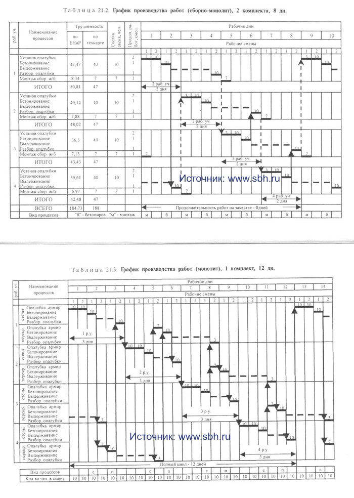
Table 21.3 WORK SCHEDULE (MONOLITH), 1 SET, 12 DAYS.
After concreting the floor section, before the workers return to this site to install the formwork of the walls of the next tier, 7.5 days pass, this time is enough for concrete to gain 70% of branded strength.
Convenient for the design and organization of work is a modular cycle of two days. During this period of time, a team of workers in one shift dismantles the formwork at the working site and, if necessary, repairs it; in two working shifts (during the day) he installs the formwork and reinforcing cages in the neighboring area, where he will carry out concreting on the first shift of the next day. The next four shifts in this area are curing the concrete, during this time the team performs a similar set of processes in another area (installation of formwork, reinforcement and concreting). In the presence of two sets of formwork and with the work of one team, the cycle of work on the grip will be 16 days, two teams will be able to complete work on two floors during this time.
The schedule for the production of works on the construction of monolithic structures of a typical floor by one team is given in Table. 21.4. The presence of two sets of formwork allows you to provide the following sequence of processes:
1) on the first section, wall formwork and reinforcement are installed;
2) in the process of curing the concrete of the walls in the first section, the team moves to the fourth, dismantles the formwork of the ceilings, installs the formwork of the walls in the third section and lays the reinforcement;
3) in the process of curing the concrete of the walls in the third section, the team returns to the first section, where it dismantles the wall formwork, installs the formwork and floor reinforcement, concretes this floor, etc.
Table 21.4 PRODUCTION SCHEDULE (MONOLITH), 2 SETS, 16 DAYS. 
The main advantages of this solution are that one team works in a constant rhythm for two days, concreting is carried out only in the first shift, for walls and ceilings in each section, the period of curing before loading is 16 days.
The schedule for the production of works for the same rhythm in two days, the implementation of the entire complex of works on the floor in 8 days with the work of two teams is given in Table. 21.5. Distinctive features of the organization of work when dividing the grip into four work areas:
• the first brigade of workers serves working sections No. 1 and 2, the second - sections No. 3 and 4;
• it is planned to move the released formwork from the first section to the third one and vice versa, the second set of formwork serves the working sections No. 2 and 4.
Table 21.5 PRODUCTION SCHEDULE (MONOLITH), 2 SETS, 8 DAYS.
The disadvantage of the adopted technology may be the concreting of walls and ceilings at the same time in neighboring areas due to the difficulties in delivering concrete to the construction site and supplying it to the installation site. The shift in time per day for the work of the teams allows concreting only on the first shift.
In modern conditions, with the use of universal formwork systems, high-speed construction with concreting of floor structures in 6 and 4 days is increasingly being introduced. The corresponding schedules for linking in time the work of independent teams on concreting walls and floors are presented in Table 21.6 and 21.7.
Table 21.6 PRODUCTION SCHEDULE (MONOLITH), 2 SETS, 6 DAYS.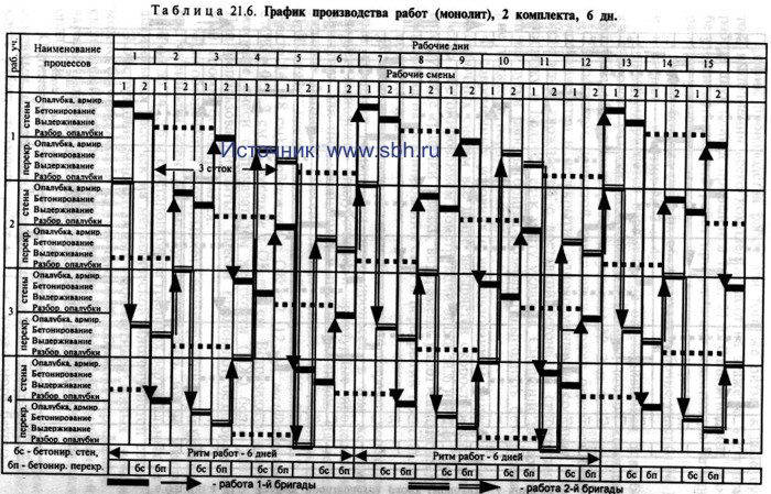
Table 21.7 WORK SCHEDULE (MONOLITH), 2 TEAM, 2 SETS, 6 DAYS. 
Based on the rate of concrete laying, the necessary set of machines for this process is selected, at the same rate, formwork and reinforcement processes should be performed on the mechanisms and devices adopted for them. The rate of laying of concrete mixtures is strongly influenced by their mobility. Apply cast mixtures with a draft of the cone (OK) more than 12 cm (often 14 ... 18 cm), mobile with OK = 2...12 cm, sedentary with OK = 0.5...2 cm and tough with OK = 0 cm. especiallytough mixtures with a hardness index (LI) of more than 200 s. When using cast mixtures, a vibration-free concreting method is used.
To ensure continuous concreting with a large length of the walls, it is recommended to divide them into sections up to 14 ... 16 m long with the installation of vertical dividing cuts from a metal multi-cellular mesh at the boundaries.
The structures of multi-storey monolithic residential buildings can be concreted in large-panel, volume-adjustable, sliding and other types of formwork. It is important that the chosen option allows mechanizing the process of installation and removal of formwork.
The best option mechanization is determined by three main indicators: duration of work; labor intensity of work; cost of work per 1 m3 of laid concrete.
In accordance with the performance of the leading stream (process) for concreting, a set of machines is selected for other streams - for the installation of formwork, installation of reinforcement, etc. It makes no sense to load the construction site with machinery, you just need to provide for the high-performance use of the main equipment. So, the crane can be involved in all the main processes - supplying formwork, reinforcement, concrete mix to the place of work, stripping.
Working with specialized streams and links allows more rational use of the formwork set and crane equipment, eliminates technological interruptions, and improves the rhythm and quality of work.
Dismantling of the formwork on the gripper can be carried out in summer conditions and in winter - after heat treatment - only when stripping strength is gained. The dismantling of the formwork is carried out in the reverse order of its installation. Loading of stripped structures is permissible when concrete gains 50 kg/cm2 of strength for walls and 100 kg/cm2 for floors.
The total duration of work on the construction of reinforced concrete structures to a height of one tier (monolithic foundations, retaining walls, clean floors or concrete preparation) or on concreting a floor of a building:
T \u003d t (m + n -1) + tb
where T - total duration of work, days; t- flow rhythm, days; m is the number of captures (working areas); P- number of executed simple processes; tb- the duration of hardening of concrete in the formwork, days.
From here, with a predetermined duration of work, you can determine the required number of captures:
m \u003d (T - tb) / t - p + 1.
2.2. MECHANIZATION OF CONCRETE WORKS
The article was prepared and submitted digitally by the company
Concrete mix is made at factories of commodity concrete. In the case when the construction site consumes more than 3000 m3 of concrete per month and it is possible to set up an on-site concrete plant (unit), its construction is economically feasible.
Transportation of concrete mix. The concrete mixture is delivered to the consumer, i.e. to the concrete work area, by concrete trucks or concrete mixers. Concrete trucks - open dump trucks with a body volume of 3 ... 5 m3 are usually used when a concrete plant is located within 10 minutes of travel to the construction site. Concrete mixer trucks are a concrete mixer with a volume of 5 ... 8 m3, installed on vehicles such as MAZ, KamAZ (for smaller volumes) and Renault, Mercedes (for large volumes). Domestic concrete mixers are produced with two modes of operation: forced mixing of the concrete mixture at the command of the driver from the cab and with mixing of the concrete mixture only when the car is moving. The disadvantage of mixers of the second type is the limited scope of their application only in the construction of facilities, where concreting is carried out strictly according to the schedule, in the event of an unforeseen waiting, unloading becomes much more complicated.
Laying concrete mix. Concrete mixture is fed into the structure in various ways: through the tray, hoisting mechanisms, concrete pumps. The first two methods are used when laying up to 50 m3 of concrete per shift, the third - for any volume, but it is economically feasible to use it when laying at least 45 m3 of concrete mix per shift. Concrete mixture is fed along the tray if it is possible to install a concrete mixer above the level of the structure to be concreted, for example, when pouring a foundation slab and the possibility of driving a car to the bottom of the pit. The trays are made of moisture-resistant plywood or metal sheets up to 6 m long. To supply the concrete mix in tubs or bunkers, the existing lifting mechanisms used for other loading and unloading operations are used. These are mainly mobile and tower cranes, sometimes they use attachment cranes. The buckets have a volume of 0.3 ... 1 m3 and, for the convenience of supplying the concrete mixture, are made in the form of a "glass", on which a vibrator is installed for its complete emptying.
Concrete pumps are the most widely used when laying concrete mix. With a laying volume of up to 80 m3 of concrete per shift, domestic or imported concrete pumps based on KamAZ, MAZ, Mercedes vehicles are used. Truck-mounted concrete pumps are equipped with a loading hopper, a pump and a distributing boom. The concrete mixture is fed in vertical (up to 80 m) and horizontal (up to 360 m) directions. In the construction of facilities with a need for more than 60 m3 of concrete per shift, as well as buildings with an increased number of storeys (more than 20 floors), stationary concrete pumps are used, complete with distributing concrete pavers. Concrete pavers with an outreach of up to 60 m are installed on the assembled building structures or auxiliary supports. The hopper of the concrete pump is connected to the concrete paver by means of a vertical pipeline through which the mixture flows. From one parking place of the concrete paver, concrete is laid on several tiers. The concrete paver, whose mass is 1...6 tons, is moved to the next parking lot by a mounting crane installed at the facility, the concrete conduit is lengthened and the concrete mixture is fed to the newly erected tiers of the building. To compact the concrete mixture, if it is required by the technology of work, vibrators for various purposes are used: for vertical structures - deep vibrators, for horizontal structures - vibrating screeds.
Comparison of the relative cost of supplying the concrete mixture to the structure by various technological sets of machines is shown in fig. 21.1. 
3. CONSTRUCTION OF BUILDINGS IN COLLAPSIBLE-REPLACEABLE FORMWORKS
There are two types of collapsible formwork: small-panel and large-panel. The installation of the former can be carried out manually, large-panel formwork requires crane installation. Modern systems Formworks are applicable for concreting foundations, columns, crossbars, walls, ceilings and other structural elements of buildings.
3.1. WALL AND COLUMN FORMWORKS
3.1.1. FINE-SHIELD FORMWORK
It consists of several types of small-sized shields made of steel, plywood, or combined, as well as fastening elements and supporting devices. Shields have an area of no more than 3 m2, the mass of one element of such formwork should not exceed 50 kg, which allows, if necessary, to install and dismantle the formwork manually. At the same time, the lateral pressure of the concrete mixture on the formwork is maintained up to 0.6 kPa. To utilize mechanisms and reduce labor costs, formwork panels can be pre-assembled into large-sized flat formwork panels or space blocks to be installed and removed using cranes.
Small-panel formworks are highly versatile, they can be used for the construction of a wide variety of structures - foundations, columns, walls, beams, ceilings. Careful surface treatment of the plywood deck makes it possible to operate it up to 200 cycles. The ease of attaching formwork panels to the frame allows you to quickly replace a worn deck.
Manufacturability of installation and dismantling of formwork systems is determined primarily by the design connecting elements. In domestic formwork, interlocks are used in the form of a coupling or a metal rod with a pin and bolted connections. Such a locking solution requires great efforts and significant labor costs during disassembly, and especially when jamming. In pre-assembly, obsolete bolted joints are often used, while foreign experience is based on the exclusion of bolted joints.
A significant disadvantage of small-panel formwork is the high labor costs for the installation and removal of formwork, the low level of mechanization of these processes.
Small-panel formwork "Framaks" of the company "Doka". Frame small-panel formwork "Framaks" is widely used on construction sites in the Moscow region. The formwork is intended for concreting walls, foundations and columns (Fig. 22.1). With a single design solution, it has a number of modifications. For lateral concrete pressures up to 80 kN/m2, a hot-dip galvanized steel frame can be used. Thanks to the closed contour and powder coating, the surface of the structure is easily and quickly cleaned from the concrete mix. At a pressure not exceeding 60 kN/m2, and the installation of elements manually, a similar aluminum frame formwork "Alu-Framax" is used. The deck for these two options is the same, the clamping and fastening devices and accessories are the same.

A feature of the Framax formwork system is a small number of formwork elements. Three heights are applicable: 135, 270 and 330 cm, in width the elements have dimensions of 135, 90, 60, 45 and 30 cm, or 5 sizes. The design of the elements and their joints allows them to be positioned both vertically and horizontally, which facilitates the formwork of surfaces of various sizes. For large formwork areas and when combining panels into a large-panel formwork, it is advisable to use a large-sized panel 2.7x2.4 m (Table 22.1).
Table 22.1 Used frame elements "Framax"
Dimensions, m |
Weight, kg |
Dimensions, m |
Weight, kg |
Dimensions, m |
Weight, kg |
Universal elements |
|||||
The deck can be made in several versions - from waterproof plywood 21 mm thick, from aluminum and galvanized steel sheets, which are attached to the frame at the back with screws, which ensures a clean and smooth surface of the concrete structure and facilitates deck replacement.
The formwork elements can be connected to each other anywhere in the frame quickly and reliably due to the fact that the contour frame of the formwork element has a special chute running along the outer profile of the frame. To connect two elements to each other, fast-acting and universal elongated (if an insert is located between the formwork panels) locks (clamps) are used, which allow you to fix the connection of the elements with a simple blow of a hammer. Doka uses quick release clamps. Screw ties are used to perceive the horizontal expansion, which ensures quick installation and removal.
The formwork is adapted for the construction of a wide variety of structures, for small and large deck heights.
Successfully solved the connection of the formwork panels with each other using screw ties into a single formwork system. To do this, use screw-threaded anchor rods inserted into the anchor sleeves specially left in the formwork frame. Anchor screws are fastened and fixed with the help of special anchor plates with a large area of contact with the surface and anchor nuts connected to the plates pivotally into a single whole. The screw tie is designed in such a way that allows the anchor screws, passing through the conical anchor sleeve, to fasten the frame elements even obliquely to each other. The design of the anchor plate provides a rigid fit to the formwork and reliable fastening of the anchor nuts.
High-strength frame frames and a rigid deck structure make the panels stable and low-deformation, allowing opposing formwork panels to be connected with just two tie-rods in height, thus providing a highly flexible system.
Small-panel formwork "Frameco" of the company "Doka". Doka currently recommends the improved frame formwork system Frameco for use. The steel hot-dip galvanized frame of the box-shaped formwork provides high strength and rigidity, protects the ends of the formwork slab from damage. The existing gutter along the outer profile of the frame allows you to connect adjacent formwork elements in any place, in a vertical and horizontal position. As connecting parts and components, you can use products of the Framax system. The frame profiles of the systems are the same, the formwork slab of the Frameco system has become thinner, its thickness is 18 mm.
The grid of standard sizes of elements has changed somewhat. The only large-sized element 2.4 x 3.0 m with a mass of 330 kg remains, the remaining elements, designed for a load of 60 kN / m2, have three nominal widths - 1.0; 0.75 and 0.5 m and two heights - 3.0 and 1.2 m (Table 22.2). For the formwork of columns, special elements have been developed that allow the pressure of the concrete mixture up to 90 kPa. The formwork panels have a width of 0.9 m and three heights - 3.0; 1.8 and 1.2 m, which allows you to optimally adjust the formwork to the required column height. The convenient location of the holes on the panels makes it possible to assemble column formwork with a cross section of up to 75 x 75 cm in 5 cm increments.
Table 22.2 APPLIED FRAME ELEMENTS "FRAMECO"
Dimensions, m |
Weight, kg |
Dimensions, m |
Weight, kg |
Dimensions, m |
Weight, kg |
|
Universalelements |
||||||
Eccentric and elongated locks allow you to quickly and firmly connect all elements of the system. The parts of each device are attached to each other, they cannot be lost. They are resistant to pollution. Locks connect adjacent formwork panels with a special pin, which is driven into a special hole in the lock with a hammer. At the same time, the connected elements of the formwork panels are pulled together, the clamping device protects the joint from stretching, due to the presence of gutters at the frame of the shields, they are straightened and are flush from the outside.
The elongated lock (universal clamping device) is designed so that its components are not lost when disconnected; it also connects adjacent formwork panels with a pin driven into a special slot with a hammer. Unlike an eccentric lock, an elongated lock allows you to install a beam or other element between the formwork panels, the total width of the joint can reach up to 15 cm.
Meva formwork systems. The German company "Meva" produces several types of formwork, common in solution, but differing in some design features. The Meva formwork system is designed for formworking any horizontal and vertical building structures, both for the smallest and largest structures under construction (Fig. 22.2). This system is distinguished by several distinctive and original design elements that have given it the recognition it deserves. The shuttering lock provides a quick and safe connection of two shuttering panels in horizontal and vertical structures at any point of the structural frame. Closed profiles of frames and stiffeners create formwork connections that successfully withstand torsion loads, facilitate the processes of joining elements, and increase construction safety. The elements of functional fastening of opposing formwork panels to each other include screw ties with special threads, which drastically reduces labor costs and facilitates all connections.
Specificity of Meva formwork panels: all panels frames are made of steel, aluminum or mixed frame, they are made of one-piece hollow profile with curved corrugation and reliable edge protection of deck elements. Patented interlocks of the formwork panels are suitable for all Meva systems and are power, which allows them to be used anywhere in the frame. When applying a lock, two shields are pulled together (they have a bottom leveled) and the lower parts of the profiles, and the elements are closed with a hammer blow by pulling them together in places of a special bevel. The lock weighs 2.8 kg and can be inserted and secured with one hand. The wedge in the lock is non-removable, which constantly ensures the completeness of the lock. The advantage of this constructive formwork solution is the rigidity of not only the panels, but also the entire formwork panel. The formwork design makes it possible to install panels not only vertically, but also horizontally, which reduces their range, while the rigidity and strength of the connection of panels does not decrease.

Shield formwork "Star tech" company "Meva"(steel frame with aluminum ribs). Formwork type "Star tech" is a universal system; it is based on steel frames made of one-piece hollow profiles with formed corrugation. The width of the profile is 4 cm, the height is 12 cm, the thickness of the profile is determined according to the conditions of static work and is accepted up to 3.6 mm. The surface of the frame is lacquered. To reduce weight, internal stiffeners - struts and struts are made of aluminum and are attached to the steel frame by adhesive bonding. This solution of the framework ensures the rigidity of the structure for crane installation with a panel area of up to 40 m2 and allows for manual installation of individual elements. The formwork is designed for a static load of 70 kN/m2. Optimal application - for foundations and walls. They produce elements with a height of 270, 135 and 90 cm, the width of the elements has 9 sizes - 270, 135, 90, 75, 55, 50, 45, 30, 25 cm. The specific weight of elements for sizes 270 and 135 cm is 55 kg per 1 m2 , for other elements the mass does not exceed 40 kg.
High-quality multilayer plywood was adopted as a deck, for elements up to 90 cm wide the plywood thickness is 15 mm, for elements 135 and 270 cm wide the plywood thickness is increased to 18 mm. The plywood is coated on both sides with synthetic resin. Sheets are attached to the frame from the outside with screws with a cutting edge, all holes are sealed with plastic sleeves, sheets are fastened to the frame with silicone.
Components and interlocks are similar to Doka connections. The lock (clamp) is installed with one hand (you can be on the stairs at the same time), it pulls the adjacent shields together, with a light hammer blow on the pin-clamp, the shields are aligned without displacement, a rigid knot is formed. To connect and unfasten the formwork panels, screw ties are also used, for the installation of which through holes are provided in the formwork frames.
The licensed production of Startek formwork is carried out in Russia.
Small-panel formwork "Alu-star" of the company "Meva"(aluminum shuttering board frame). Formwork "Alu-star" of the company "Meva" has frames made of aluminum one-piece two-chamber profiles. The width of the profile is taken equal to 4 cm, the height is 12 cm. The thickness of the profile for elements of various areas is linked to the specifics of static work. The frame is additionally reinforced with a transverse rib, which is not in metal frame Startech systems. The surface of the profile is protected by a plastic coating, which increases its impact resistance and scratch resistance. Design load - 60 kN/m2.
The nomenclature of elements includes two heights - 270 and 135 cm, only 7 sizes are accepted in width for both heights - 90, 75, 55, 50, 45, 30 and 25 cm. elements, the mass is within 30 kg per 1 m2.
For the deck, high-quality multilayer plywood 15 cm thick is used, coated on both sides with synthetic resin - a plastic powder coating that repels concrete, which significantly reduces the cost of cleaning the formwork. The plywood is fixed to the frame with screws with a cutting edge, the holes are sealed with conical plastic sleeves, the adjoining of the shields to the frame is protected by silicone.
Components similar to those of the Doka company were used. To connect two shields to each other, two lock joints are sufficient. Screw ties are used for fixing all auxiliary elements and for spreading the formwork. Crossbars 50 cm long are also used for the final leveling of the installed formwork panel.
Formwork has significant advantages. Thanks to the use of a two-chamber and one-piece profile, the frame has become rigid and durable. The use of an aluminum frame in the frame reduced the weight of the products, all panels can be installed manually, i.e. there is no formwork crane installation. Light locking connections are used. The plastic deck coating is adhesive, shock and scratch resistant. With a light hammer blow, mechanical damage to the surface of the shields is excluded. All this leads to a significant reduction in the time for their cleaning for reuse.
Small-panel frame formwork "EcoAz" is designed for formwork of strip and glass type foundations and provides for manual assembly. Shields have a height of 2400, 1600, 1200 and 800 mm; width from 250 to 800 mm, the maximum weight of the panel is 60 kg, the load on the formwork is 50 kN/m2.
Small-panel formwork "Rasto" of the company "Thyssen". The German company Thyssen widely implements its formwork systems. In particular, it has developed formwork sets that complement each other, namely, Rasto small-panel formwork, Manto large-panel formwork and Sompakt slab formwork.
Formwork "Rasto" is designed for manual installation of panels. It is easy to use, durable, withstands the pressure of the concrete mixture up to 60 kN/m2, is versatile, and can be used in various areas of construction.
The main element is a shield with a height of 270 cm; for tall structures, additional shields with a height of 150 cm, a width of 45 to 90 cm with a gradation of 5 cm are applicable. Shields are easy to combine vertically and horizontally, adjustment is carried out along the length with a module of 5 cm, shield extension is possible both when the horizontal seams coincide, and when they are displaced.
The formwork panels of the Rasto system are made of hot-dip galvanized steel, the formwork elements have high endurance and strength. The formwork frame is made of a metal profile 12 cm high, along the perimeter it has a protrusion 14 mm high, which protects the ends of the deck of the same thickness from all sides. The frame is equipped with longitudinal ribs every 30 cm, depending on the width of the shields, it has 1 ... 2 transverse ribs. The presence of corner fasteners in certain places ensures high rigidity and stability of the panels, and the use of hollow profiles for the frame significantly reduces their weight. The 2.7 x 0.75 m shield weighs only 60 kg and can be moved and assembled by hand.
To connect the shields, universal locks (rasto-squeezes) are used. An eccentric lock (combi-squeeze) 40 cm long connects two adjacent elements in one working turn of the lamb butt-to-butt, counteracting tension, possible vibration and pressure of the concrete mixture. The compress not only aligns and ensures the coaxiality of the shields, the rigidity of the joint allows crane lifting of shields with a total area of up to 40 m2. When it is necessary to connect “standing” and “lying” boards or to install an insert up to 15 cm wide between the boards, elongated locks (sliding combi-clamps) 55 cm long are used. Special corner sliding clamps with a backlash of up to 6 cm have also been developed. Rasto" allow one movement of the strap to hook the clamping pads, providing a tight connection of adjacent shields. The dismantling of these eccentric wedge locks is simple and does not require extra effort. Interlock connections are located during installation, two interlocks per two abutting panels and allow easy dismantling without compromising the stability of the overall formwork system.
If not the entire range of Rasto small-panel formwork products is used, then five-centimeter compensators (inserts) are used for installation in the formwork along the length of the wall and in the corner parts. The formwork kit may include special column formwork panels that allow you to have rectangular and square shapes ranging in size from 15 x 15 to 55 x 55 cm.
Screw ties are provided for connecting the formwork panels to each other, unfastening the formwork of columns, walls and partitions. There are spacers (sleeves) of different lengths for aligning the formwork panels, ensuring the spatial rigidity of the system of panels - the formwork block during installation and concreting.
Small-panel formwork by Dally. Dally formwork consists of modular elements, which makes it possible to complete the formwork panel with vertical and horizontal panels. The main advantage of the formwork is that from a minimum number of elements and original fasteners, it is possible to manually assemble the formwork of a wide variety of horizontal and vertical structures. Boards are produced in three sizes in height - 264, 132 and 88 cm and 10 sizes in width - from 75 to 20 cm with a gradation of 5 cm. Standard boards measuring 264 x 75 cm have a mass of 60 kg, manual installation of formwork elements is allowed. At the ends of each shield, two welded hex nuts are provided for a strong pin connection of two adjacent shields (Fig. 22.3).
The working surface of the formwork is a 5-layer wooden board 21 mm thick with double-sided reinforced cladding, which allows using each formwork element at least 350 times with regular cleaning and lubrication. The frame elements of the shields are made of sheet steel with overlays and scarves, which makes the frame quite rigid, but this solution can significantly reduce the weight of the shield. Each shield is attached with just two tie rods,
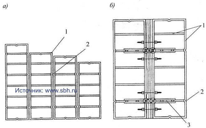
final fastening - with a wing nut by hand. The company has developed its own bolted (lockless) clamps, which are inserted into the through hole of two adjacent shields and tightly compressed with one blow of a hammer. If two adjacent shields are vertically displaced, then a special bracket can be used, which is also fixed anywhere with one blow of a hammer. This fastening occurs due to two cams, with the help of which the formwork profiles are pressed together. The shuttering bracket is removed by hitting the hammer in the opposite direction.
For the formation of corner joints, external and internal corner elements are provided, which allow docking panels at any angle. Special adjustable tin sheet levelers-inserts have been developed, thanks to which it is possible to form a formwork

panel of exactly the required dimensions. The specificity of panels and corner joints allows the use of Dally formwork from standard elements for walls of different thicknesses, heights, and various outlines of the structure in plan.
The connection of opposite formwork panels and their mutual fixation can be carried out using special screw couplers with a wing nut; the tie screw is passed through special half holes of two adjoining panels, which are provided on the end surfaces of the formwork.
Dalli column formwork is designed for 4 element heights - 300, 264, 132 and 100 cm (Fig. 22.4), the design allows you to increase the height of the panels, the dimensions of the columns are from 10 x 10 to 80 x 80 cm in increments of 2 .5 cm
The article was prepared and submitted digitally by the company
The paragraph about "RINGER" was added to the content of the article by SBH COTPAHC (www.website):
Shallow formwork by "RINGER" (Austria): RINGER formwork includes several types, common in design and fully compatible with each other. They differ in some design features. The formwork is intended for the formation of any horizontal and vertical structures of structures under construction (Fig. 5.1). The formwork design has several characteristic original solutions that ensure long-term operation of the panels and ease of assembly.

The company produces three types of formwork systems:
1) Alu-Master- aluminum formwork for loads up to 60 kN/m2,
2)
Steel Master- steel formwork for loads up to 80 kN/m2,
3)
Alu-2000- aluminum budget formwork model with a simplified profile for loads up to 60 kN/m2.
The formwork lock is the main connecting element of the boards and can be installed with one hand, as it has a self-locking design. The force locking of the lock is made with the other hand with one blow of the hammer on the wedge. The wedge of the lock is non-removable, which excludes its loss. Only 2 locks are enough for vertical connection of boards with a height of 270 cm. The lock connections are power, which allows using locks anywhere in the frame. When installing the lock, the shields are pulled together and aligned. The design of the locks ensures the rigidity of the whole formwork panel, consisting of several boards. Shields can be installed both vertically and horizontally.

Shield formwork STEEL-MASTER and ALU-MASTER of the firm "RINGER". The formwork frame MASTER (Fig. 5.2) consists of rigid non-twisting edge profiles with a stable shape. Inside the frame there is an oblique rib that increases rigidity, providing strength and preventing deformation. To install fasteners on the edge profile, a clamping place is provided, reinforced with an oblique rib. In places where the formwork deck overlaps, the frame has a special protrusion that protects the edges of the shield from damage. Two support platforms greatly facilitate the cleaning of the shields. To reinforce the frame, edge (along the perimeter of the shield) and functional (across the shield) profiles are welded to it, forming a support for the deck. As a deck, you can use both Finnish plywood and plastic PRIMUS - each deck is screwed to the frame with screws. Functional profiles are made in such a way that other structural elements are easily attached to them - tension clamps, supports, etc. The width of the frame profile is 123 mm, its surface is powder coated for easy cleaning.
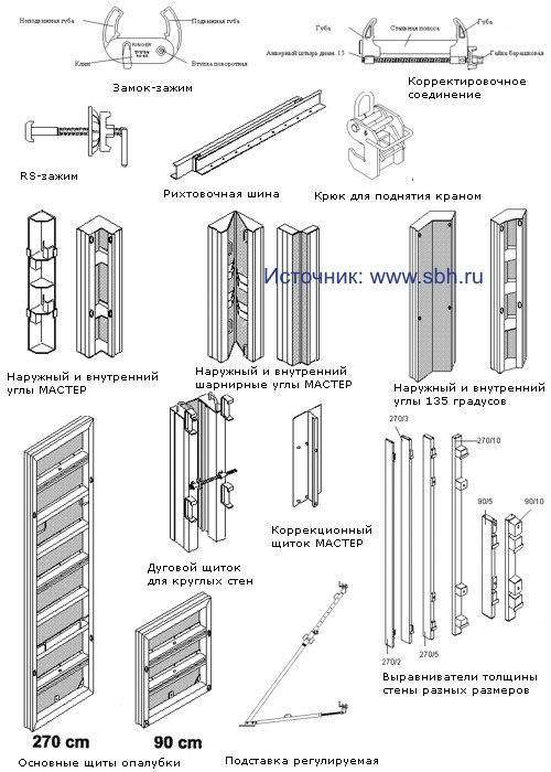
Formwork STEEL-MASTER consists of panels with a steel frame in three lengths - 330, 270 and 135 cm and ten widths (Table 5.1).
Table 5.1 Steel formwork panels "RINGER STEEL-MASTER"
Dimensions, m |
Weight, kg |
Dimensions, m |
Weight, kg |
Dimensions, m |
Weight, kg |
Universal elements |
|||||
ALU-MASTER formwork consists of aluminum panels of two lengths - 270 and 90 cm and eight widths (Table 5.2). The dimensions of the width are selected in such a way that they can be used to form a surface of any configuration. Aluminum formwork has an important advantage compared to steel formwork - the low weight of the panels allows for manual assembly.
Table 5.2 Aluminum formwork panels "RINGER ALU-MASTER"
Dimensions, m |
Weight, kg |
Dimensions, m |
Weight, kg |
Universal elements |
|||
There are 4 welded through bushings in the formwork frame. To facilitate the threading of the anchor pins, the bushings are cone-shaped. The use of anchor pins makes it possible to eliminate the distortion of the formwork elements and their displacement in height.

Universal elements are used to form columns (Fig. 5.6) or form corners (Fig. 5.5). The difference between the universal shield and the usual one of the same dimensions is that the universal shield has holes in the frame. The distance between the holes of 5 cm makes it possible to vary the value of the wall thickness or the section of the column in the range from 20 to 65 cm for ALU-MASTER or from 20 to 85 cm for STEEL-MASTER.

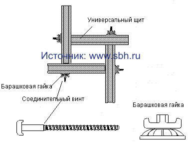
To connect the universal boards, only a universal connecting screw and a combination wing nut are needed.
Angles of 90 degrees are formed using the MASTER inner and outer corners (Fig. 5.7). Corners are produced with a length corresponding to the length of the formwork panels. 
To obtain sharp and obtuse angles from 60 to 180 degrees, internal and external hinged corners MASTER are used (Fig. 5.8). Hinged corners have a height of 330, 270, 135, 90 cm. The length of the sides of the inner corner is 30 cm, the outer corner is 6.5 cm.

Making 135 degree corners is greatly facilitated by the availability of pre-made 135 degree corners. Fixed corners are more stable and stable than articulated corners and do not require the use of additional leveling rails. The 135-degree corners are made in such a way that with a wall thickness of 25 cm, the inner and outer corners are connected without the use of any additional elements.
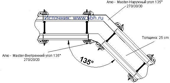
With MASTER arc shields you can create round walls in a polygonal way (in the form of a polygon). Arc shields are combined with shields. To obtain the desired radius, a spacer bolt is used. The minimum inner radius is 1.8 m. The arc shields are connected to the shields with clamps (Fig. 5.3).
With the help of correction shields, gaps from 4 to 20 cm can be filled. A plank is used to equalize the thickness of the wall (Fig. 5.3).
Adjustment joints up to 20 cm wide are made using the Master clamp. With a panel height of 270 cm, only 2 clamps are required to fill gaps or to add to a finished wall.
Adjustment joints up to 20 cm wide are made using a clamp. The distance between the lips of the clamp is adjusted by a screw pin.
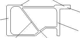

To stiffen structures of considerable height, leveling rails MASTER 150 are used. Leveling rails MASTER 100 are designed to level the joints between boards or boards and the finished wall. The straightening rail is attached to the functional profile using the tension clamp MASTER-RS (Fig. 5.3). The straightening rail can also be attached to anchors. 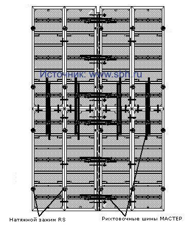

Installation of panels with an inclination is possible with the help of a special inclined sleeve in the formwork frame. The shields are connected with a tension bolt and a combi-washer. Since the bolt holes are tapered, the shields can be tilted. The bowl of the combi-washer is equipped with a hinge, which ensures a snug fit to the frame.


Panel formwork ALU-2000 by "RINGER". This formwork system is a budget version of the ALU-MASTER system and is distinguished by a simpler frame design (without an internal oblique rib). The frame thickness is reduced to 10 cm. Despite this, the formwork allows you to work with the same load of 60 KN/m2 and at the same time has a 15% lower cost. Simplification of the frame design reduces the number of formwork cycles by 5-10%.
Table 5.3 Aluminum formwork panels "RINGER ALU-2000"
Dimensions, m |
Weight, kg |
Dimensions, m |
Weight, kg |
Universal elements |
|||
The article was prepared and submitted digitally by the company
3.1.2. LARGE-SHIELD FORMWORK
The formwork includes boards with an area of 3...20 m2 of increased bearing capacity and is used for structures with large formwork surfaces. Formwork elements combine the deck with supporting purlins and ribs. Increasing the dimensions of the formwork boards makes it possible to drastically reduce the labor intensity of work on formwork structures and to more fully realize the complex mechanization of processes. Large-panel formwork is the most versatile and mobile in use and can significantly improve the quality of structures by reducing the number of interfaces, while the height of the shield is taken equal to the height of the concreting tier.
The formwork is intended for the construction of large-sized monolithic structures of a wide variety of structures, the installation and removal of the formwork is carried out only by cranes. Formwork panels are self-supporting and include a deck, shield stiffeners and load-bearing structures. Such shields are equipped with scaffolds, struts for installation and initial alignment, and adjusting jacks.
Large-panel formwork is applicable for almost all structural elements of buildings and structures: foundations, external and internal walls, columns, floors. Formwork has found the greatest distribution in the construction of residential and civil buildings.
In multi-storey housing construction, when using large-panel formwork, it is preferable to have external walls made of prefabricated prefabricated panels (three-layer with effective insulation), expanded clay concrete or brick. Internal load-bearing walls are made of monolithic reinforced concrete. A common design scheme is in which reinforced concrete columns are carriers with a beam or beamless ceiling. For prefabricated and brick exterior walls, it is advisable to lag behind the installation of one floor from the production of concrete work.
Depending on the thickness of the structure to be concreted and the requirements for the quality of the surfaces, the formwork shield is made from a supporting frame and a deck for the entire formwork plane or a formwork panel is assembled from separate inventory panels connected by a system of locks. Two opposing formwork panels are interconnected by a system of horizontal screw ties that are passed through the body of the future concrete structure and installed before concreting. To ensure the stability of the formwork and align it to the design position, use various systems struts and braces, equipped with mechanical screw jacks and adjusting devices (Fig. 22.5).
The wall formwork is installed in two stages. First, the reinforcing cage is mounted, then the formwork on one side of the wall to the entire height of the floor, and at the last stage of work, the formwork on the second side. When accepting the formwork, the geometric dimensions, the coincidence of the axes, the verticality and horizontality of the formwork panels, embedded parts, the density of joints and seams are controlled.
The concrete mixture is placed into the formwork from above from the cantilever scaffolds fixed on it, located on the outside of the shield. Concreting of walls is carried out in sections, the boundaries are usually doorways. The bunker with concrete mixture is always unloaded at several points, while the mixture is placed into the formwork in layers of 30...40 cm thick with compaction by deep vibrators immediately upon laying. To perceive the pressure of the concrete mixture during the installation of the formwork, special inventory bushings are used, and sometimes additional liners. Formwork panels for walls and ceilings are often made to the size of the area to be concreted (cells of the building); this area should not exceed 70 m2.
The formwork is installed in a sequence determined by its design and ensuring the stability of individual elements and the formwork as a whole in the process of work.
Large-panel formwork "Mammut" of the company "Meva"(for massive structures). Mammut formwork is applicable for all types of construction, but it is most widely used in residential construction.
For the design pressure of the concrete mix up to 100 kN/m2, the Mammut reinforced formwork system has been developed. Formwork frames are made of high-strength one-piece steel hollow profiles with formed corrugation. The height of the profile, as in the small-panel formwork, remained the same - 12 cm, but the width increased to 6 cm; The thickness of the profile for individual shields reaches, according to the conditions of static operation, 3.8 mm. The surface of the frame is lacquered.
In terms of height, 3 sizes are accepted - 300, 250 and 125 cm, for each height 4 values \u200b\u200bof the width of the elements are accepted - 250, 125, 100 and 75 cm, but if necessary, elements of the same height can be supplied with a width of 60 to 25 cm in increments 5 cm. Accepted standard sizes make it possible to obtain a formwork panel of almost any size. Only crane installation of the formwork is provided, the weight of the panels is within 62 kg per 1 m2. The constructive solution of the formwork makes it possible to provide the specified rigidity of the system even at a concrete mixture pressure of up to 97 kN/m2. For this formwork, it is acceptable to use external vibrators for pneumatic compaction of the concrete mix.
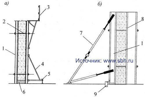
Based on the design pressure of the concrete mixture, a multilayer high-quality plywood 21 mm thick is used, treated on both sides with synthetic resin - a plastic coating. Fastening to the frame from the side of the flooring with screws with a cutting edge, the holes are sealed with plastic sleeves, the connection of the shields with the frame is protected by silicone.
As components, by analogy with other systems, interlocks are used - two per element, universal interlocks (if necessary, coupling screws) for fastening all auxiliary parts to the elements and for spreading the formwork. The set includes crossbars for transverse alignment and leveling of the surface.
Lock connections can be installed anywhere in the frame. These are special locks of the same constructive solution, simple, reliable and easy to use. Screw ties - standard. All components are durable enough due to hot-dip galvanization.
The advantage of the formwork is the permissible height of the device up to 4.5 m without additional fastenings and braces, the formwork can withstand high-speed concreting.
MevaDek slab formwork provides four different solutions: a system of main and auxiliary beams with formwork covering; overlapping transverse beams in the form of a system of wooden beams with a formwork coating of ready-made panels or simply laminated plywood; panel system; use of drop head props to facilitate stripping.
Large-panel formwork "Manto" of the company "Thyssen". Large-panel formwork "Manto" is designed for the construction of large residential and industrial facilities. A wide range of shields with a height of 2.7 m for residential and 3.3 m for industrial and civil construction has been developed. The formwork is designed to withstand the pressure of the concrete mixture up to 80 kN / m2 (Fig. 22.6).
The frame frame consists of a 14 cm high galvanized metal profile of complex shape, which provides high resistance to bending. Hot-dip galvanizing facilitates shields, eliminates corrosion, and sharply reduces the adhesion of the frame. The accepted dimensions of the frame in combination with other stability elements give the shields special strength, allow them to withstand the hydrostatic pressure of the concrete mix up to 3.3 m high. Shields up to 5.4 m high can do without bracing.

Ordinary formwork panels are produced with a height of 330, 270, 120 and 60 cm and a width of 45 to 330 cm. All panels in any position are combined with each other horizontally and vertically, with a height or horizontal offset. Formwork panels can be recognized as universal, since the two functional grooves on the inside of their frame guarantee the optimal use of various connecting means developed by different companies. All boards have a steel framing profile along the contour, which protects the plastic-coated multi-layer board made of precious wood from impacts and damage.
To connect the shields to each other, special straightening clamps are used, which provide a simple, fast, reliable connection of two elements that is well resistant to stretching and vibration. Rigidity and strength of the connection make it possible to lift formwork panels with an area of up to 40 m2 during crane installation without additional fastening. In addition to the connection, the locks simultaneously straighten and align the shields. They can be used when shields are shifted in height, when they are built up. For joining two formwork panels maximum dimensions two locks are enough.
For concreting tape and columnar foundations and columns can be managed with a minimum number of elements. To form the foundations, the boards are laid "lying down". For concreting columns, you can use a specially designed formwork, but it is permissible to use conventional shields and corner locks. Depending on the pressure of the concrete in the screw screeds, Dividag threaded screws DV15 and DV20 are used. Large-sized washers and nuts of the tie rods provide good load distribution, effective use of the bearing capacity of the screws, and reliable resistance to the pressure of the concrete mixture.
Collapsible formwork for walls and columns by NOE. The formwork system "NOE 2000" for the needs of construction is produced in four modifications - the main steel frame formwork (Fig. 22.7) with any required coating, including steel, designed for a load of up to 80 kN / m2 with a height of panels up to 3.31 m and a maximum formwork area shield up to 14.05 m 2; lightweight system with steel frame, allowing craneless installation; an aluminum formwork designed exclusively for manual work, and a universal formwork for columns, allowing a concrete mixture pressure of up to 125 kN/m2. Wall formwork can be assembled in different combinations with panels arranged vertically or horizontally.
Standard dimensions of steel frame formwork; element width 265; 132.5; 125; 100; 75; 50 and 25 cm; height 331; 300 and 265 cm, deck turnover 70...90 times, steel frame - 500 revolutions. For a lightweight system, elements with a width of 530 and 331 cm and a height of 265 are additionally applicable; 132.5 and 66 cm.

The covering of the boards is always made in one piece without inserts and extensions, even for boards measuring 265 x 530 cm. As a deck, waterproof wood-glued three-layer boards with a thickness of 21 and 22 mm or a structural wooden plate of the required thickness according to the calculation can be used; the deck is always attached to the shields from the back. These advantages make it possible to have a high turnover of the panels, an optimal view of the stripped surface and simplify the cleaning of the panels. Most often, birch is used for formwork coating in 15 layers with a total thickness of 21 mm with a double-sided phenol coating applied.
The external solid groove in the strapping frame of the formwork board allows the boards to be attached to each other in any place. To assemble panels into a single formwork panel, wedge-shaped and screw clamps are used for ordinary connections and elongated clamps for leveling panels with inserts up to 25 cm wide, while the strength of the joint and the entire formwork panel is not reduced. All steel elements of the formwork must be hot-dip galvanized, which not only improves the appearance, but also increases the turnover of the panels, significantly reduces adhesion to concrete.
Pure steel frame formwork is always bulky and heavy. HOE Lightweight Formwork is a variant that combines the economy and strength of a steel frame with aluminum stiffeners.
The aluminum formwork of the NOE company has 4 standard sizes in width - 90, 75, 50 and 25 cm, two in height - 265 and 132.5 cm, shield turnover 60 ... 80 times, frames - 400 turns. The deck made of waterproof 9-layer plywood with a total thickness of 15 mm is riveted on the front side, a protective layer is sprayed on top to facilitate stripping and maintenance of the panels. The formwork is light, allows manual installation; if necessary, shields of other types and modifications can be used within the framework of the "NOE 2000" system. In addition, all corner plates, leveling inserts and other fasteners are the same and can be used if necessary.
The column formwork of the NOE company consists of four panels (Fig. 22.8), which allow you to smoothly adjust their width from 15 to 150 cm, the height of the panels is 300, 275, 100 and 50 cm, it is possible to connect the panels in height using standard connecting elements. The formwork frame is all steel, it is strong and durable, the board covering is optionally made of multi-layer, three-layer plywood, boards or 4mm steel sheet. turnover wood flooring within 20...30 cycles, steel frame, including steel deck, up to 400 times. Connection of shields on bolts or on special triangular plates.

Shield wall formwork by Utinor. The French company "Utinor" is a recognized leader in the production of metal formwork. For walls, columns, ceilings, elevator shafts, etc., various types of formwork have been developed with a formwork surface in the form of a 4-mm steel sheet, thanks to it and a rigid frame, the strength of the formwork is significantly increased, the standard formwork turnover is 800 cycles. Most often, large-panel formwork is used for walls and ceilings, tunnel formwork.
Currently Utinor manufactures three models of wall formwork - standard, folding and container formwork. Folding formwork is an intermediate solution between standard panel formwork and container formwork.
Standard wall formwork consists of vertical panels 2.52 high; 2.60 and 2.70 m and a module length of 1.25 m, which allows you to have elements in the set from 1.25 to 6.25 m. Formwork panels consist of a forming metal sheet 3 or 4 mm thick with stiffening elements and load-bearing structures (trusses, beams), which perceive the forces from the concrete mixture and provide the necessary stability of the formwork and the possibility of its adjustment (Fig. 22.9).
For two-sided wall formation, two formwork panels are fixed to each other in the “face to face” position using lifting “goats”, thanks to which the stability of both panels is constantly ensured for the required time. When stripping, both shields are slinged, lifted by a crane, thanks to their design, the "goats" automatically push the shields apart.
When the wall formwork is moved to a new working position, the panels are in a fixed non-working position at a distance of 1.1 m from each other, which allows the installation of reinforcing cages, other embedded parts and inserts. In preparation for concreting, the installation and fastening of the panels in the design position is carried out using special retractable rollers. The shields are connected with couplers (studs), and the upper coupler is above the level of concreting, and the lower one is located at the very base of the wall. No other irregularities and holes are formed after concreting the wall. The required distance between the formwork panels (thickness of the concreted structure) in the upper part of the formwork is set and provided during the concreting process by the gantry frame structure, in the lower part - with the help of special lever devices.
Each wall formwork is equipped at the base with jacks for setting it to the desired level and two lifting brackets at the head. The vertical trusses bearing the load from the concrete mix are fixed on the formwork in increments of 1.25 m (3 elements per shield 3.75 m long) and have a jack at the base to set the entire formwork panel strictly vertically. Each wall shield is equipped with a working platform and a ladder.
Metal formwork has a high quality forming surface. The perfect joining of the forming surfaces of the two wallboards is ensured by special guiding and connecting levers and locking pins. Threaded ties (studs), distribution plates and wing nuts provide a rigid mutual installation of two opposite panels and perceive the pressure of the concrete mix poured into the formwork. Special bushings-spacers are put on each coupler, which rigidly fix the distance between two opposing wall shields from the inside, the bushings are placed under each truss in the lower and upper parts of the shield.
In cases where the required height of the concrete wall to be erected exceeds the height of the standard wall formwork, top additional panels are used, inserted in the upper part of the main shield. With a height of addition of not more than 0.35 m, their position is adjusted using screws resting on inner surface formwork stiffeners; for inserts up to 1 m, special stabilizers with adjusting screws are used. When the height of the additional elements is more than 1 m, special additional trusses are used, connected to the main supporting trusses. All efforts from the pressure of the concrete mixture are transferred from the additional elements to the main formwork panels.

An important element For high-quality and coaxial concreting of a structure vertically is concreting at the zero level of socles 60 ... 100 mm high with extended reinforcement. The plinths must be concreted simultaneously with the floor slabs above the basement; when concreting the floor of the first floor, the plinths of the walls of the second floor must be concreted.
The surfaces obtained as a result of concreting practically do not require any refinement, due to which the amount of finishing work is significantly reduced. Metal formwork allows the use of window, door and other openings, which are fixed with magnetic clamps directly on metal panels, which makes it possible to quickly and efficiently install window and door frames and frames in these openings. These openings can be rigid and manufactured to specific dimensions, or they can be retractable and used to varying sizes. They can immediately contain window and door frames, which in this case are automatically built into concrete structure, or simply designate openings into which the same window and door frames are later mounted.
Removing the previously assembled formwork and installing it at a new workplace is not particularly difficult. When stripping the previously concreted wall, screw ties and screws of the opening formers are removed, the jacks of the trusses are loosened, the end cut-offs of the walls are disconnected and the formwork panels are separated (pushed apart), which are then moved to the next grip.
The dismantling of the formwork of individual panels begins with the removal of the jacks of the trusses after their preliminary weakening, after which the panels are separated from the concrete surface, lean back, but thanks to the "goats" they retain the necessary stability. After stripping, the working surface must be rinsed with a jet of water, cleaned with a scraper and lubricated with special oil. The formwork is installed in a new place above the already concreted plinth. On the shield in the right places, all the necessary opening formers are mounted, removed from the already concreted walls; a team of electricians places junction boxes, switches on the formwork and carries out cabling. Reinforcement workers install reinforcing meshes and frames, connecting them to each other and to the reinforcing bars released from the base. Then the formwork panels are pressed against the plinth, connected to each other and aligned vertically and horizontally with the help of jacks. After that, screw ties are inserted, bushings are put on them, the shields are finally pulled close to the base and tightened with the help of screw ties.
The final position of the formwork is fixed after adjusting the horizontality and verticality of the formwork. At the final stage of the formwork installation, the ends of the walls are closed with cut-offs, which, after adjustment, are rigidly fixed along the edges of the formwork.
In standard wall formwork, when transporting to a new construction site, it is necessary to dismantle hinged platforms, stiffening trusses and other frame elements. Folding formwork is equipped with swivel and side-folding tooling elements, which makes it possible to drastically reduce its dimensions during transportation.
Container wall formwork by Utinor. It is produced in a modular version with a length of 1.25 and 2.5 m for standard heights of 2.52 and 2.60 m. formwork combinations in height. The stiffening ribs of the formwork frame are designed in the form of a caisson with a rib spacing of 15 cm, which guarantees increased rigidity and strength to the deck made of a 4 mm thick forming sheet. All corners of the formwork are equipped with special container locks - the main element of the connection between the panels. Thanks to these locks, the panels are well protected from deformations; adjacent panels are connected by tightening special screw ties. At the same time, docking and alignment of the connected formwork panels is guaranteed without additional adjustment.
Container wall formwork is fully folded: the working platform (platform and fence) and stabilizing struts are not dismantled during transportation.
An important advantage of the Utinor metal formwork is that it can be transformed in height, width and length, i.e. it can be used for a wide variety of projects with different wall thicknesses, floor heights and spans up to 8.2 m. Using the technology of Utinor, it is possible to reduce the cost of construction compared to large-panel construction by up to 30%, and with high-speed and year-round work, it is possible to reduce the construction time.
Formwork system "Kaplock". The formwork system "Kaplock" was developed in the UK, it is universal, it can be used for formwork of walls and ceilings, as a supporting part of bridges, tunnels and other tall structures, and as an easy-to-use scaffolding system for finishing various structures outside and inside.
Two types of wall formwork panels are offered with a height of 2.7 and 1.5 m (Fig. 22.10), designed for a lateral pressure of the concrete mixture up to 6 kPa with a deck of laminated plywood with a thickness of 18 mm.
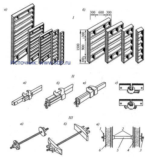
Table 22.3. Boards formwork system "Kaplock"
Shield size, mm |
Weight, kg |
Shield size, mm |
Weight, kg |
To ensure multiple turnover of panels (Table 22.3) and all other elements of the formwork system, their metal parts are subjected to deep hot galvanizing, which gives a coating of more High Quality than conventional paint galvanization. The quality of the coating guarantees high resistance to corrosion and mechanical damage for 5...6 years. Convenience, ease of connection and fastening of elements contribute to the durability of the coating, reducing maintenance costs.
To connect the shields into the formwork panel, original locks have been developed that have side locking, which is more convenient during operation and more reliable than metal pins hammered from above. Locks have a number of varieties depending on the specific application: an eccentric lock and two types of elongated locks with a side wing nut.
Screw ties have their own distinctive features, which have three varieties, including ties that allow you to connect opposing panels along their upper faces, and ties with inserts (spacer sleeves) that prevent thinning of the section of the concreted structure.
The article was prepared and submitted digitally by the company
3.2. Floor formwork
When installing the beam ceiling formwork, the sequence of work will be as follows (Fig. 22.11). First, the reinforcing cage of the columns is installed, then the formwork of the columns is mounted with fastening with screw ties or clamps and fastening in 2 ... 3 levels with braces. To interface with the overlying structures, the reinforcement of the columns is released 40 ... 50 cm above the upper edge of the formwork. Then the columns are concreted. After that, shields of the bottom of beams or girders are laid on special cutouts in the formwork of columns, supporting telescopic racks or spatial supports are installed under them and adjusted in height. Racks for spatial rigidity are mounted on tripods. After installing the side panels of the formwork of the beams and connecting them to each other with horizontal screw ties, they are fastened to the bottom shield. At the next stage, racks are installed under secondary wooden beams, a deck of moisture-resistant plywood is spread over them.
After laying the reinforcing cages and meshes, laying pipes for internal wiring, concreting is carried out. Formwork dismantling is recommended to be carried out after concrete has gained stripping strength and in the reverse order of formwork installation.
Among the domestic formworks, the unified formwork developed by the TsNIIOMTP Institute is the most common. The wall formwork consists of boards one floor high with a modular width of 300 to 1800 mm, as well as additional boards - end and corner. The shield consists of a metal deck, horizontal beams and vertical trusses. Screw jacks are provided at the bottom of the shields. In the formwork, it is possible to concrete walls with a thickness of 12, 16 and 20 cm at a height of up to 3 m and ceilings with a thickness of 10 ... 22 cm.
A monolithic ceiling is arranged after the walls have been erected and they have gained the necessary initial strength. The slab formwork is mounted on telescopic props, reinforcing meshes are laid in two levels, and concreting is carried out.

For large-panel formwork, a universal slab formwork, the so-called "table formwork", has been developed. It consists of a set of modular elements that make it possible to assemble formwork with a shield length of up to 12 m, a width of up to 5.6 m and a height from the parking level of 1.75 to 10 m. Formwork is removed by reducing the height of the table supports. Next, the formwork is rolled out from under the ceiling and rearranged to another place. Installation and rearrangement is carried out with a "duck nose" traverse.
At present, a collapsible-adjustable large-panel formwork made of aluminum alloys for walls and ceilings, developed at the TsNIIOMTP Institute, has been developed and has found application. The purpose, scope and design of this formwork are discussed in detail in the textbook of the authors "Technology of building processes" (Part 2. - M: Higher school, 2003.).
Sompakt formwork by Thyssen(Fig. 22.12). It allows you to arrange formwork for floors of any length, width and thickness. This is achieved due to the fact that all the constituent elements of the formwork are fitted to each other, have significant strength and durability. In general, the formwork consists of the following load-bearing elements: H20 compact beams, applicable for the installation of any floors; extendable tripods with basic steel posts, extendable rods and removable heads (fork and support) for easy demoulding and a “falling” head for lowering only this post up to 10 cm.
Formwork installation is carried out in the following sequence. Removable heads, including "falling" ones, are installed from above into the racks, the racks are fixed in the design position, and by extending the tripod, they receive the necessary spatial stability. Bearing longitudinal beams are installed in the removable heads of the racks, along which the transverse beams are placed, shields or simply formwork sheets are laid out on top. To carry out stripping, the “falling” heads are lowered down (for different modifications by 6 ... 10 cm), as a result, the entire formwork system flexes somewhat. It becomes possible relatively simply to release the individual longitudinal and transverse beams and to remove, if necessary, the formwork panels. More often, the lowering of “falling” heads is used to remove intermediate racks from under the formwork after the concrete of the concreted structure of the floor has reached sufficient strength.

A feature of the formwork system is that the detachable head of the rack can hold two overlapping beams at once, which can be easily moved along this head, so the design is applicable to any shape of the formwork in plan. Racks-tripods, stable in themselves, as well as the longitudinal and transverse beams located along them, can be spaced at distances corresponding to the requirements of the load that they will perceive. For significant loads, distances should be shorter; for smaller slab thicknesses and lower formwork loads, the distances between props and overhead purlins can be increased.
This formwork system uses H20 wooden beams. They are made of high-strength northern spruce, have the shape of an I-beam with "convex" sides and fairly wide and stable belts. This compact shape makes the beam strong and stable, while the five-layer bonding dramatically increases overall rigidity. The beam, even if nails are nailed along the edges, does not split. If necessary, it can be sawn anywhere, even obliquely, which does not reduce the strength characteristics. The beam does not deform when falling, is little subject to wear, impregnation protects it from decay. Wooden girders are relatively light and can be installed manually by two people. The cross section of the beams makes it easy to tilt them and install them in the right place. With such runs, in comparison with metal ones, it is easier, easier, and therefore faster to work.
Formwork system "Meva Dek". It is intended for horizontal structures and ceilings. The main advantage of this system is that it uses all known horizontal formwork technologies, which makes it possible to create four different formwork systems.
The combination of these systems makes it possible, for each specific case, to minimize the resurfacing surface, and the use of props with removable heads, including “falling ones,” makes it possible to leave only separate intermediate props in an accelerated stripping option, which saves significant time and money.

Widespread use has found a wooden glued beam H20, designed for manual assembly on metal racks with a “falling” head of a system of main and secondary beams, while creating a universal formwork system (Fig. 22.13). The standard dimensions of the beams (at a height of 20 cm) are 250, 330, 390 and 450 mm, beams of other sizes can be made on request.
Slab formwork system "NOE"
1. Formwork from the main beams and formwork panels. The slab formwork system with load-bearing elements made of aluminum alloys has found application. The system consists of props with "falling" heads, ceiling beams and formwork panels (Fig. 22.14). Formwork panels are 150 and 120 cm long and 90 to 30 cm wide (15 cm step). Longitudinal ceiling beams along the axes of the supports can have dimensions of 300, 210, 180, 150 and 120 cm, the “falling” head is galvanized steel with a height of 36 cm, lowering the head, if necessary, up to 17 cm. shields.
The same swivel head formwork system allows for a free choice of formwork cover. The design is applicable for slabs with drops or with a strong division of the slab structure. On standard racks with a "falling" or swivel head, longitudinal beams of the same dimensions are laid (see above), and transverse crossbars are placed along the lower chords. The solution allows you to have a free choice of formwork cover. Depending on the installation of the transverse beams, the formwork (shuttering sheets or panels) can be laid both between the longitudinal beams and on them.
2. Formwork with sliding secondary beams. The ceiling shaped system of the company "NOE" (Fig. 22.15), compatible with aluminum formwork, is its further development and improvement. Racks with a "falling" head take the load from the roof panels even with one-sided loading without the moment of bending of the supports. Secondary beams - sliding from 100 to 150 cm, telescopic type. As an option, a shaped system of large-sized panels supported directly on the flanges of the main beams is applicable, which allows easy assembly and dismantling of the panels. The range of boards has a pitch of 15 and 30 cm, which makes it possible to optimally spread the formwork over the entire area of the room with minimal additions. The design solution allows you to have a snug fit to the wall and secure fastening with it. If necessary, it is possible to use longitudinal beams with a length of 3 m, which significantly reduces the number of required posts and simplifies the process of their installation under the formwork ceiling panels.


3. Ceiling formwork with falling heads. This solution is universal, it includes a ceiling formwork with "falling" heads and a supporting system of longitudinal beams and ceiling panels (Fig. 22.16). The beams are installed on "falling" heads, which are pre-attached to the heads of the retractable rods of the support posts. In the "falling" heads, the bearing crossbars are pinched, the tripods of the racks provide stability during the installation of the crossbars. Formwork panels are laid on the assembled supporting structure of the formwork, the laying is carried out quickly both in the longitudinal and transverse directions. The advantage of this solution is the possibility of early stripping, while the racks with a "falling" head constantly support the stripped ceiling. The removed formwork panels can be mounted at this time on the adjacent grip on spare supports.

4. Formwork with H20 beams. H20 wooden beams have been widely used in the formwork system of the NOE company. The whole system consists of wooden beams, fork heads, standard supports and tripods and covering in the form of shields or sheets of plywood (Fig. 22.17). Formwork is installed manually. It is especially suitable for enclosed spaces. The disadvantage of this system is the reduced turnover of beams (up to 50 turns) and shields (up to 20 turns).
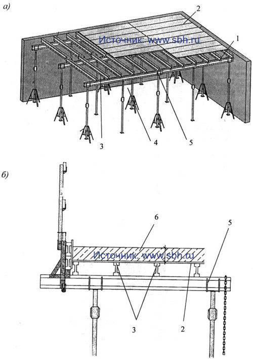
Dally formwork for slabs. The constructive formwork solution is traditional - sliding racks, H20 wood-glued beams, on the upper shelves of which formwork panels are laid, intended for walls, as well as special panels of similar sizes (but only 132 and 88 cm long) (Fig. 22.18). Racks of three standard sizes of variable length 1.5...3; 2...3.5 and 2.3...4.1 m, H20 beams standard sizes, for stripping, a U-shaped beam holder with a “falling” head is installed on the sliding racks.

Slab formwork by Utinor. Firm "Utinor" offers three independent options for formwork for concreting floors: non-removable formwork made of self-supporting elements, which, in the presence of temporary intermediate supports, can withstand not only their own weight, but also the weight of the laid concrete mixture; small-panel formwork for craneless installation and molding tables.
The article was prepared and submitted digitally by the company
Small-panel formwork contains three main elements: a standard post with a forked head fixed on top, a metal profile beam and panels consisting of a steel frame and a laminated plywood sheet. Sliding racks make it possible to use formwork for rooms with a floor height of 2 to 5.2 m. Bearing beams 1.0 and 1.6 m long allow, if necessary, to increase them within 0.6 ... 0.9 m. 30 and 60 cm wide and 0.9 to 1.5 m long (the heaviest formwork element weighs 26 kg). After dismantling the panels and beams, the concreted slab is supported using standard racks with fork, support and falling heads.
Standard forming table firm "Utinor". The design of the table allows it to be used at a room height of 2 to 2.5 m and spans from 1.9 to 6 m. The working surface is made in the form of a metal sheet 3 mm thick or large-sized plywood sheets 18...21 mm thick. The table consists of sliding transverse beams mounted on the longitudinal beams of the table frame. The metal cover is attached to the sliding beams through welded stiffeners, plywood - with brackets and countersunk bolts.
Lattice longitudinal and transverse beams V-shape have a length of 1.2 to 5.4 m in increments of 60 cm, which allows you to get a deck with a span of up to 6 m. Each supporting leg is equipped with a manually operated screw lever jack with a stroke of 690 mm and a wheel with a diameter of 200 mm for moving the formwork along the span.
First, with the help of screw jacks on the supporting legs and according to the level of the reference marks on the upper part of the walls, the table is set in height, the side clearance stripping rails are adjusted (they indicate the formwork dimensions along the perimeter of the room), and then the opening formers, electrical equipment and cable wiring are installed, the necessary communications are laid and lay reinforcing mesh.
Stripping rails are installed on each side of the table. They allow you to choose the gap created during installation between the table and adjoining walls, and to easily lower the forming table after the concrete has set. Dismantling of the table is carried out under the action of gravity and solely due to its supporting legs and the gap between the table and the bottom of the floor of 30 ... 40 cm created with their help when lowering on the jacks. supports and it is easy to roll it to the edge of the slab for subsequent extension and rearrangement. At the same time, temporary support posts are installed in the released span to support the concrete slab that has not yet gained strength.
When concreting the floors of the second floor, to remove the tables, stripping platforms or cantilever scaffolds should be used, the load from which is transferred to the floor slab of the first floor that has already gained sufficient strength. There are several options for extracting tables with a crane. The table can be rolled out onto scaffolds that serve as a continuation of the slab, and can be lifted from them by a crane using a four-branch sling. The table can also be lifted by crane and without scaffolding using a special traverse or balancing device.
At low (but not negative) temperatures, to maintain the temperature of the concrete due to exothermic heat, to accelerate its hardening, it is recommended to cover the concrete slab with a light heat-insulating material type of polystyrene. At high temperature ambient air, on the contrary, it is advisable to carry out concreting late in the evening, and pour water over the ceiling in the morning to prevent cracking of the concrete until the table is moved.
Ceiling formwork "Kaplock". The Kaplok support system is currently one of the most durable and versatile load-bearing systems available. An important feature system is not the integrity of the telescopic racks, but their assembly from individual elements to the desired height.
Racks are designed in two varieties - bushless and bushing connections (Fig. 22.19). Racks, depending on the length, have 2...6 cup connections, the cups are welded to the racks through 50 cm in length. Racks of sleeveless connection can be used independently, screw jacks can be fixed on them. Bush connection racks are used in combination with bushless racks; they have bushings 150 mm long for vertical connection with other racks. Holes are provided for additional fastening of racks to each other on locking cotter pins or dowels.
Each connection consists of two cups, the upper, mobile, in the form of a cap, is made of malleable casting, which contributes to its safety and durability. The lower cup, fixed at a certain height (in increments of 50 cm), is made on the outside in the form of a bowl, and inside it has four special bores for inserting horizontal ties. The design of the racks allows their mutual extension to the required height. Rack pipes made of high-strength steel with a wall thickness of 3.2 mm made it possible to significantly lighten the entire system, while the load on one rack can reach 64 kN.
The set of racks includes a support having a welded tube 110 mm high. The support can be used at the bottom of the rack as a base (heel) and at the top as a head. For the upper part of the racks, fixed forks made of wood, steel or aluminum are used to install the beams close to each other (with a fork width of 150 mm) or with an angular offset (with a fork width of 200 mm). A "falling" head and a swinging fork have found application, used when the racks have a fracture in one or two directions. An important component is a universal screw jack, its use is possible in the upper and lower parts of the racks. There are two types of screw jacks with a coupling - with an element length of 400 mm, its cutting is 250 mm, with an element length of 860 mm, the cutting increases to 620 mm. Jacks are designed for precise adjustment support system, used in connection with a fork or heel, are fixed in the cavity of the cup joint. They are designed for a certain load when installing the necessary horizontal and diagonal ties.

Horizontal links have a length of 600, 900...1300 (with a step of 100 mm), 1600, 1800 and 2500 mm. These links allow the racks to be placed at a distance of 60 to 250 cm according to the requirement of the project, they can be located on different levels in height, providing spatial rigidity to the entire support system. Horizontals and racks, if necessary, can be used as quick connection and disconnection scaffolding. Each horizontal has at the ends a forged nozzle (limiter) of great strength and a special design, which is rigidly included in the special bore of the lower cups of the racks.
The "Kaplock" system, having an original connection of elements, provides a quick assembly of the frame in knots. The method of nodal assembly of horizontal elements is based on their preliminary installation on supports in the lower cups of the racks, there can be four such elements. The upper cup is lowered onto the limit switches of horizontal connections installed at the joint, while it rigidly captures these limit switches and is fixed with one blow of the hammer, forming a rigid connection. Such a joint of horizontal elements at the same level is convenient, the complete assembly is simplified, and stresses in the assembly are reduced. The advantage of the support system is also that it is solved without bolts, wedges, nuts.
The load-bearing aluminum beams of the frame (Fig. 22.20, Table 22.4) have three varieties, depending on the bearing load and the span to be covered.
Table 22.4. Beams of the frame system "Kaplock"
Beam T150 |
Beam T225 |
||||||||||
Weight, kg |
Weight, kg |
Weight, kg |
Weight, kg |
Weight, kg |
Weight, kg |
||||||

Options for securing scaffolding, installing load-bearing and secondary beams of the floor formwork are shown in fig. 22.20, II. An important advantage of the support-formwork system is the simplicity of the constructive solution and the possibility of quick assembly and disassembly. The operating range of the installed jack is 620 mm (in other formwork systems - 100...200 mm), the distance between support legs may vary considerably. The system is designed for craneless assembly of the entire frame; load-bearing aluminum beams with wood inserts are convenient and technologically advanced, allowing for a distance between the frame columns of up to 7.5 m with a mass carrier beam formwork 67 kg. The presence of wooden inserts in the beams provides reliable fastening of the deck of plywood sheets and formwork panels of various designs. For a preliminary comparison of various formwork systems, fig. 22.21 shows the distribution of specific labor costs for the installation of formwork for slabs.
The article was prepared and submitted digitally by the company


